Article

Low Phase Noise Millimeter-Wave Generation Based on Optoelectronic Feed-Forward

1
State Key Laboratory of Information Photonics and Optical Communications, Beijing University of Posts and Telecommunications, Beijing 100876, China
2
State Key Laboratory of Optoelectronic Materials and Devices, Institute of Semiconductors, Chinese Academy of Sciences, Beijing 100083, China
3
College of Materials Science and Opto-Electronic Technology, University of Chinese Academy of Sciences, Beijing 100049, China
4
School of Electronic, Electrical and Communication Engineering, University of Chinese Academy of Sciences, Beijing 100049, China
*
Author to whom correspondence should be addressed.
Photonics 2025, 12(8), 757; https://doi.org/10.3390/photonics12080757
Submission received: 17 June 2025 / Revised: 24 July 2025 / Accepted: 26 July 2025 / Published: 28 July 2025
(This article belongs to the Special Issue Optoelectronic Oscillators (OEO): Principles and Applications)

Abstract

In this paper, we propose an optoelectronic feed-forward millimeter-wave generator based on the Mach–Zehnder interferometer (MZI) structure. The phase noise of the local oscillation (LO) input is extracted by loop design and used for phase noise suppression of the output, thereby optimizing the phase noise performance of the generator output. The scheme achieves separation of the phase noise by using an MZI structure and a mixing-frequency oscillator to realize the differential and integration process of the phase noise from the LO input source, respectively. Then, it is combined with a feed-forward operation to skillfully realize phase noise rejection of the resulting high-frequency output. The proposed scheme has been demonstrated to facilitate millimeter-wave generation at 40 GHz and 50 GHz. The measured phase noise is as low as −120 dBc/Hz at a 10 kHz offset, and the experimental setup achieves phase noise suppression of up to 36 dB at this frequency offset. Through systematic theoretical analysis and experimental verification, the excellent capabilities of the proposed scheme in high-frequency signal generation and phase noise suppression are fully demonstrated, which provides a new technological path for high-performance millimeter-wave generation, avoiding the deterioration of the phase noise introduced using high-frequency optoelectronic devices other than photodetectors (PDs) to process the signals.

1. Introduction

High-frequency signals with ultra-low phase noise and high spectral purity have important applications in modern high-performance communication systems, precision radar, and high-precision electronic measurement systems. The millimeter wave offers promising solutions for high-speed data transmission due to its vast bandwidth advantages, significantly enhancing channel capacity and transmission rates [1,2,3]. Studies have demonstrated that the phase noise performance of a signal source directly influences key system metrics: in radar systems, low phase noise improves target detection resolution and sensitivity, while in communication systems, it enhances signal-to-noise ratio (SNR) and reduces bit error rate. However, conventional electronic methods face fundamental limitations in generating high-frequency signals, with phase noise performance deteriorating sharply as the frequency increases [4]. In contrast, photonics-based methods overcome these electronic bottlenecks. In the field of microwave photonics, OEOs have garnered significant attention due to their exceptional phase noise performance. First proposed by X.S. Yao and L. Maleki [5], the core innovation of OEO technology lies in the use of optical fiber as a high-quality-factor (Q) energy storage element to construct an optoelectronic hybrid feedback loop. It has been demonstrated that optimizing the length of the optical fiber can significantly enhance the system’s quality factor, leading to the generation of microwave with ultra-low phase noise [6,7].
Significant progress has been made in recent years in the development of low-phase-noise oscillation generation techniques based on OEOs [8,9,10,11], and a variety of innovative schemes have emerged. Typical representatives include the zero-bias Mach–Zehnder modulator OEO structure, the uptime-symmetric OEO architectures, and the optical frequency comb-assisted OEO technology, which are all capable of efficiently realizing high-frequency oscillation generation. The latest research on OEO technology shows a phase noise performance of −145 dBc/Hz at 10 GHz frequency offset [12]. However, the systems face multiple challenges in achieving a balance between low phase noise and high-frequency performance, especially in the operating scenarios required for millimeter-wave generation. The narrow bandwidth characteristics of high-frequency filters based on conventional principles conflict with the need for mode-spurious rejection due to physical principles and process limitations. At the same time, the optoelectronic devices used in such structures bring about inevitable phase noise performance deterioration [13,14,15]. The modulation bandwidth of the optical modulator is limited by the half-wave voltage, which results in an increased noise floor of the output oscillation. In addition, the noise figure of the loop amplifier deteriorates significantly in the millimeter-wave band, further exacerbating the deterioration of the system phase noise. These factors combine to limit an improvement in performance. Recently, many methods for generating low-phase-noise microwave and millimeter-wave signals have emerged, enabling stable oscillating generation across frequency bands from tens of GHz to the terahertz range [16,17,18,19], including mode-locked optical frequency comb frequency division (100 GHz, −114 dBc/Hz@10 kHz) [20,21,22], Brillouin oscillators (10 GHz, −95 dBc/Hz@10 Hz, and −110 dBc/Hz@100 Hz) [23,24], and micro-resonator optical frequency combs (25 GHz, −141 dBc/Hz@10 kHz) [25,26]. These optical-domain frequency synthesis techniques not only offer higher accuracy and stability but also display excellent broadband reconfigurability, providing innovative approaches to generating ultra-low phase noise signals.
To eliminate the requirement of devices in generating millimeter-wave using the OEO scheme, this paper proposes a new improved optoelectronic hybrid oscillating architecture based on the MZI. The differential phase noise is first realized using the MZI with non-equal arm lengths, and then, the integration process of the phase noise is down-frequency-converted to be completed using a low-frequency narrow-band filter with a high Q value. Through the well-designed link delay matching relationship, the system successfully achieves effective extraction of phase noise, the electrical oscillator completes the integration process of phase noise, and the result produced by the integration action of the electric oscillator only reflects the phase noise characteristics of the LO input. Meanwhile, we have innovatively introduced the feed-forward suppression structure to actively eliminate the residual phase noise in the oscillator output and ultimately generate ultra-low phase noise signals in the high-frequency band. The experimental study fully verifies the superior performance of this scheme. The generator successfully obtains high-quality output at 22 GHz, 40 GHz, and 50 GHz by flexibly adjusting the frequency of the LO input. The results show that the scheme achieves a phase noise of −120 dBc/Hz at a 10 kHz frequency offset and a 36 dB phase noise suppression ratio for the LO input. The theoretical analysis and experimental verification highlight two key advantages of the architecture: first, the system achieves excellent phase noise suppression while maintaining high-frequency output, and second, the system’s high suppression ratio can be adapted to the worse phase noise and higher-frequency LO input. These characteristics make it an ideal solution for ultra-low phase noise millimeter-wave generation in the high-frequency band, offering a reliable and high-performance microwave source for next-generation communication, radar, and measurement systems.

2. Principles and Methods
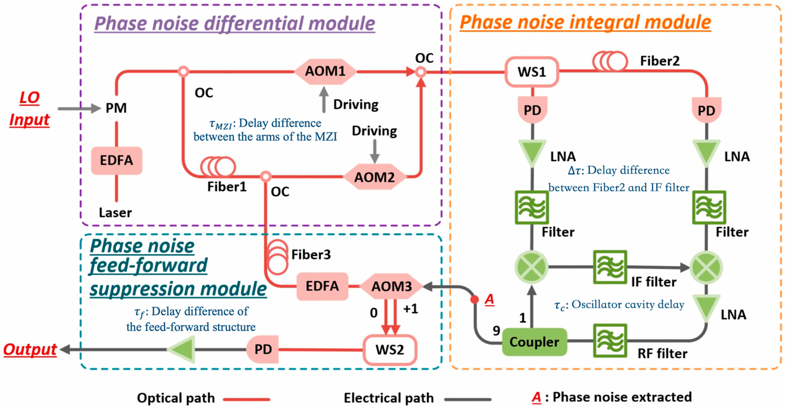
2.1. Principles

In traditional OEO architectures, the system is described in terms of oscillating behaviors, but our proposed optoelectronic hybrid feed-forward millimeter-wave generator focuses on the phase noise transformation process. The detailed experimental schematic is presented in Figure 1, where the entire setup is partitioned into three functional modules distinguished by colored dashed boxes. The red dashed box highlights the phase noise differential module of the experimental setup, which uses the LO input to modulate the optical source and performs the phase noise differential operation through the unequal-arm-length MZI structure. The block diagram of the phase noise integral module is shown within the yellow dashed circle and primarily consists of the optoelectronic hybrid oscillator. This oscillator is responsible for noise integration of LO and phase noise suppression from other sources. These two modules work together to extract phase noise from the LO input, with the resulting output indicated at position A in the figure. The feed-forward suppression module, highlighted in blue in the figure, utilizes a frequency-shifting modulator and a PD to suppress the phase noise of the LO, which was extracted in the previous stage. This configuration enables the generation of spectrally pure millimeter waves.

2.2. Analysis and Theoretical Calculation Results

The differential module consists of the generation of the optical carrier and the MZI structure. The phase noise of the LO input is denoted by φ L O t . Meanwhile, the delay difference between the upper and lower interferometer arms of the MZI is defined as τ M Z I , which is mainly determined by transmission Fiber1. The frequency-shifted component of the frequency comb is the difference in frequency between the center frequencies of the AOMs, and here, we mainly consider the positive and negative first-order modulation sidebands of the optical source. The combined optical carrier after the OC contains the phase noise of the optical source and AOM driving, in addition to the phase noise of the LO input. With the MZI structure with a non-equal arm length, the phase noise is retained in the link in a differential form. Taking the positive first-order sideband as an example, the differential phase noise of the LO input is denoted as φ L O t τ M Z I φ L O t .
Following the introduction of differential phase noise, the second part of the system employs a programmable WaveShaper (WS) to perform frequency separation, selectively isolating the positive and negative first-order modulation sidebands. In practical experiments, the filtering frequency of WS1 can be dynamically configured via software, endowing the system with exceptional flexibility in output frequency tuning. Specifically, the positive first-order sideband is routed to the PD of the left link, and the delay-matched compensating fiber (Fiber2) with the same delay as the IF filter is added to the other side of the link. Since the filters behind PDs have the same parameters, the effect of the delay difference on the transmitted signal can be neglected. Based on the structural characteristics of the mixing-frequency pair filter model, when the delay induced by the IF filter precisely matches that of Fiber2, the homogenous phase noise contained in the mixer’s driving is completely suppressed. Assuming that the delay difference is expressed as τ , the multiplication factor of the corresponding phase noise term in the power spectral density can be expressed as 4 s i n 2 π f τ . This operation effectively suppresses the phase noise from both the optical source and the AOM driving in the optoelectronic hybrid oscillator output. In contrast, the phase noise of the LO input contained in the driving of the mixer originates from different modulation sidebands and cannot be canceled due to the opposite sign of the differential form of the phase noise.
The differential form power spectral density of phase noise for AOM1 and AOM2 is defined as S φ A O M 2 π f . S φ o 2 π f and S φ L O 2 π f are the power spectral densities of phase noise for the optical and LO input, respectively. We can obtain a relationship between the extracted phase noise S φ e x t r a c t 2 π f at point A and the above phase noise as follows:
S φ e x t r a c t 2 π f = 4 c o s 2 π f τ s i n 2 π f τ d s i n 2 π f τ c S φ L O 2 π f + s i n 2 π f τ s i n 2 π f τ c 4 s i n 2 π f τ d S φ o 2 π f + S φ A O M 2 π f
Among them, τ c is the delay time of the electric oscillating loop. According to the theoretical analysis of Equation (1), the sin-squared term containing τ is close to 0, and the cos-squared term is close to 1 when the link delays are well-matched. Simultaneously, we establish the equivalence between the delay difference of the MZI’s arm length and the ring length of the electric oscillator and then obtain the phase noise extraction result at point A as 4 S φ L O 2 π f . According to the phase conversion relationship, its equivalent phase noise satisfies φ e x t r a c t t = 2 φ L O t , which is suppressed and eliminated in the subsequent feed-forward module.
In the feed-forward suppression module, the result of point A is used as a frequency-shifted modulation unit. Here, the modulation sidebands and their frequency-shifted results are generated via the dual modulation ports of AOM3. The modulation result is frequency-selected by WS2, whose filtering parameters are similar to WS1. The final frequency of the PD output is the superposition of the AOM3 driving frequency and the second harmonic of the LO input. Mathematically denoted as 2 f L O + f e x t r a c t , the two frequencies originate from the LO and extracted signal (about 24 MHz), respectively.
After the PD frequency tap, the phase noise of the LO input is completely suppressed. However, the narrow operating bandwidth of the frequency shift modulator introduces a group delay of approximately 3.6 μs. To compensate for this, Fiber3 needs to be added to the feed-forward optical link, with the sum of the delays with Fiber1 being equal to the transmission delay of AOM3, to ensure that the phase noise contained in the optical and electrical noise cancels each other out.
Thus, in principle, the structure contains three delay matches: the first two for extracting the phase noise and the remaining one for achieving phase noise delamination in the feed-forward link. Considering the delay mismatch within the loop, the phase noise spectral density of the output from the proposed optoelectronic hybrid millimeter-wave generator can be expressed as:
S φ o u t p u t 2 π f = 4 e i 2 π f τ f e i 2 π f τ M Z I 1 e i 2 π f τ c 1 2 S φ L O 2 π f
where τ f is the delay mismatch value of the feed-forward link. We simulated the noise suppression effect of the system with different levels of delay mismatch. The horizontal axis in Figure 2 indicates the effect of delay matching for the MZI’s arm length difference versus the oscillator cavity length; the vertical axis indicates the degree of mismatch between the compensated fibers for phase noise suppression and AOM3 delay.
By analyzing the equations above, we theoretically prove that the low phase noise output generation can be achieved by the proposed novel optoelectronic hybrid millimeter-wave generator architecture, and the frequency of the output only depends on the frequency difference between the first-order modulation sidebands. Under the condition that the delays of each part are well-matched, the system can output millimeter waves with low phase noise performance at an arbitrary frequency by changing the frequency of the LO input.

3. Experiments and Results

3.1. Experimental Setup

The laser generates an optical source with a central frequency of 193.4 THz, which is modulated by an LO input generated by an signal generator. The modulated sidebands are transmitted through the MZI structure, where the OC splitting ratios for splitting and combining are 5:5. The driving frequencies of AOM1 and AOM2 are 214 MHz and 120 MHz, respectively. The combined result is filtered by the programmable WS with the frequency parameters set according to the positive and negative first-order sideband frequencies after modulation. The power at the output of the PD is −21dBm, which is then amplified and filtered by the LNA. The filters used have a center frequency of 90 MHz and a 3 dB bandwidth of 40 MHz, introducing a delay of approximately 27 ns to the mixer driving. The IF filters operate in the 67.5–92.5 MHz band, and the oscillator output is about 24.3 MHz, which falls within the narrow-band filter of 400 kHz. Also, the electrical oscillator loop produces a delay of 2.3 us.

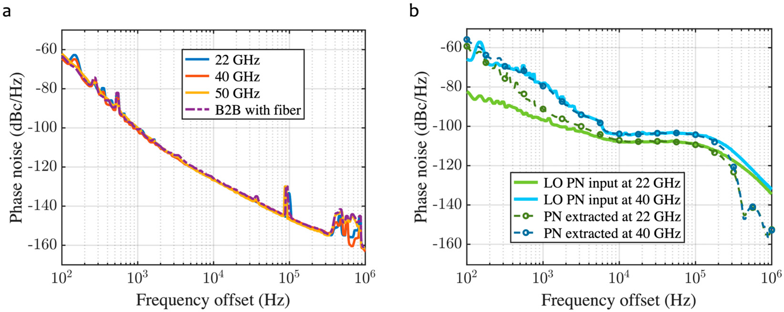
3.2. Measurement of Extracted Phase Noise Results

Without the inclusion of Fiber1, as derived from Equation (1), the extraction result at point A is shown to exclude the three primary phase noise source terms of the system. In this case, the extracted result at the output of the electronic oscillator characterizes the background phase noise of the system. As shown in Figure 3a, we measured the results at LO input frequencies of 11 GHz, 20 GHz, and 25 GHz using a spectrum analyzer. Although the LO input frequencies are different, the outputs are all around −126 dBc/Hz at a 10 kHz frequency offset, and this result corresponds to the theoretical analysis in the previous section. The background phase noise (−126 dBc/Hz) arises from intrinsic system components, including shot noise of the PD, thermal noise of LNAs, and RIN of the laser. These noise sources are inherent to the components and exhibit frequency-flat behavior within the measured LO frequency range (11 GHz, 20 GHz, and 25 GHz). Since the LO frequency modulates optical sidebands without affecting the noise properties of these components, the background noise floor remains consistent.
To verify whether the long optical fiber used in the experimental setup affects the noise results, we included equal-length fibers of 400 m in each of the two arms of the MZI and compared the experimental results with the case without fibers. The results show that the measurements are consistent in both cases, and the possibility that the long optical fiber causes the deterioration of the background noise can be ruled out.
After adding the Fiber1 in the intrametric arm of the MZI, the result extracted after the integration module is four times the phase noise of the LO input. For specific experiments, we compared the theoretical values of LO phase noise introduced into the system to the experimentally extracted results for the cases of modulation comb spacing of 22 GHz and 40 GHz, for example. As shown in Figure 3b, the phase noise behavior is the same for both cases. The deviations in the results within the 10 kHz frequency offset originate from the oscillator’s noise floor effect. The above observations indicate that the integration function of phase noise is implemented in the electrical oscillator. Notably, the delay mismatch value of about 7.3 ns is obtained by backpropagating the influence factor s i n 2 π f τ , which proves that the delays in the mixing-frequency pair structure have been well-matched [27].

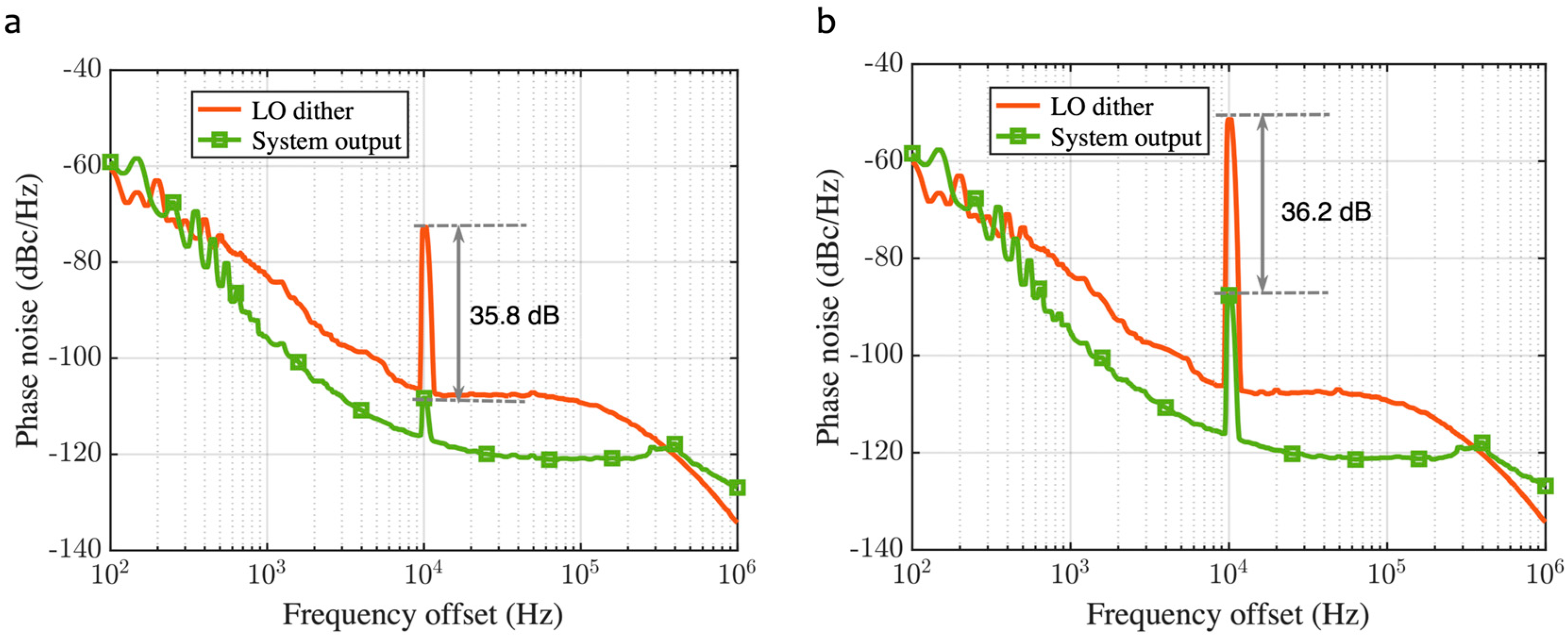
3.3. Measurement of Suppressed Phase Noise Results

In the feed-forward suppression module, according to the frequency of the LO input, the phase noise results of the output of the proposed generator are shown as the three solid lines in Figure 4a. In addition, the above results are compared to the extracted phase noise, denoted as the green curve.
The experimental results show that our proposed structure can generate pure millimeter waves with a phase noise of −120 dBc/Hz at a 10 kHz frequency offset regardless of the frequency of the generated output. The results show almost the same degree of degradation in the frequency range from 100 Hz to 30 kHz compared to the background noise, which is mainly due to the degradation of the SNR when using matched fibers. Meanwhile, the phase noise elevation follows the same trend as the multiplication factor of delay matching in the rest of the frequency range. Since the spectrum analyzer limits the frequency observation to 50.1 GHz, we set the optical frequency comb repetition frequency to a maximum of 25 GHz.
Figure 4b shows the spectral information of the output at different frequencies spanning a 10 GHz bandwidth obtained using a spectrometer. To facilitate comparison of the results, the center of the oscillating frequency is shifted to the same frequency reference. The inset shows the spectral details in a 5 MHz bandwidth after zooming in.

3.4. Greater Phase Noise Tolerance Range for LO Input

Significantly, the background phase noise reference results for comparison were measured at an output frequency of 20 GHz, where the system produces 16 dB phase noise suppression of the LO input. However, the suppression performance of the actual system is much larger than this value. When the phase noise of the LO deteriorates with increasing modulation frequency, the generator can still produce higher frequency outputs at a −120 dBc/Hz phase noise reference.
The above theory was experimentally verified by artificially introducing the frequency dither of the LO input to observe the phase noise suppression effect of the structure. Dither was introduced at a frequency offset of 10 kHz, and the suppression effects were examined separately for different dither modulation indices. The solid lines in Figure 5 represent the phase noise with introduced spuriousness, and the dotted lines show the output of the experimental setup. The suppression at the test frequency offset in the figure can reach 36 dB. It demonstrates that even if the phase noise of the modulated LO source deteriorates, the experimental setup is still able to compensate for it through the effect of a high suppression ratio.
Based on the relationship between the suppression ratio and the degree of delay mismatch simulated in the previous section, it can be deduced that the delay matching accuracy reaches the ns level.

4. Discussion

Our optoelectronic feed-forward millimeter-wave generators achieve low phase noise and excellent broadband reconfigurability for 40–50 GHz signals. It overcomes the application requirements of traditional OEO schemes for high-frequency devices in millimeter-wave operating scenarios and avoids the complexity of high-Q optical cavities and stabilization required by other photonic methods. The simplicity and high performance of our approach make it a pioneering solution for high-frequency communication and radar systems, with future work focusing on robustness and frequency scaling.

5. Conclusions

In this study, a novel MZI-based feed-forward millimeter-wave generator architecture is proposed, which innovatively combines the MZI and a delay matching mechanism to accomplish phase noise extraction and suppression in the loop. A system with a high phase noise suppression ratio that can effectively avoid the additional noise when using high-frequency optics is successfully constructed, and its phase noise does not deteriorate with an increase in LO input frequency. In comparison to conventional OEOs, the proposed hybrid optoelectronic oscillator architecture overcomes the limitations of using filters for spurious side-mode suppression in high-frequency applications while preserving the loop’s high-Q characteristic. We theoretically analyze the feasibility of the scheme and experimentally verify the generation of millimeter waves with low phase noise performance. The excellent performance of the proposed system in phase noise suppression is analyzed thoroughly, providing a new technological paradigm for millimeter-wave generation.

Author Contributions

Conceptualization, T.Y., Y.L. and Y.D.; methodology, T.Y.; software, T.Y.; validation, T.Y., X.W. and Z.F.; formal analysis, T.Y.; investigation, C.L.; resources, F.Y. and M.L.; data curation, T.Y.; writing—original draft preparation, T.Y.; writing—review and editing, T.Y., Q.C. and Y.D.; visualization, T.Y.; supervision, T.Y.; project administration, Y.D.; funding acquisition, Y.D. and K.X. All authors have read and agreed to the published version of the manuscript.

Funding

This work was supported by the National Natural Science Foundation of China (62135014).

Institutional Review Board Statement

Not applicable.

Informed Consent Statement

Not applicable.

Data Availability Statement

Data are contained within the article.

Conflicts of Interest

The authors declare no conflicts of interest.

Abbreviations

The following abbreviations are used in this manuscript:
PNPhase Noise
PMPhase Modulator
OCOptical Coupler
LNALow-Noise Amplifier
AOMAcousto-Optic Modulator
IFIntermediate Frequency
EDFAErbium-Doped Fiber Amplifier
LOLocal Oscillation
MZIMach–Zehnder Interferometer
PDPhotodetector

References

  1. Ghelfi, P.; Laghezza, F.; Scotti, F.; Serafino, G.; Capria, A.; Pinna, S.; Onori, D.; Porzi, C.; Scaffardi, M.; Malacarne, A. A fully photonics-based coherent radar system. Nature 2014, 507, 341–345. [Google Scholar] [CrossRef] [PubMed]
  2. Aubry, A.; Carotenuto, V.; Farina, A.; De Maio, A. Radar phase noise modeling and effects-part II: Pulse doppler processors and sidelobe blankers. IEEE Trans. Aerosp. Electron. Syst. 2016, 52, 712–725. [Google Scholar] [CrossRef]
  3. Axelsson, S.R.J. Noise radar using random phase and frequency modulation. IEEE Trans. Geosci. Remote Sens. 2004, 42, 2370–2384. [Google Scholar] [CrossRef]
  4. Cundiff, S.T.; Ye, J. Colloquium: Femtosecond optical frequency combs. Rev. Mod. Phys. 2003, 75, 325. [Google Scholar] [CrossRef]
  5. Yao, X.S.; Maleki, L. Optoelectronic microwave oscillator. J. Opt. Soc. Am. B 1996, 13, 1725–1735. [Google Scholar] [CrossRef]
  6. Maleki, L. The optoelectronic oscillator. Nat. Photonics 2011, 5, 728–730. [Google Scholar] [CrossRef]
  7. Gao, H.; Dai, J.; Guo, M.; Zhang, T.; Xu, K. Fiber noise suppression for the low phase noise OEO. In AOPC 2024: AI in Optics and Photonics; SPIE: Bellingham, WA, USA, 2024; pp. 248–251. [Google Scholar]
  8. Hao, T.; Liu, Y.; Tang, J.; Cen, Q.; Li, W.; Zhu, N.; Dai, Y.; Capmany, J.; Yao, J.; Li, M. Recent advances in optoelectronic oscillators. Adv. Photonics 2020, 2, 044001. [Google Scholar] [CrossRef]
  9. Ge, Z.; Hao, T.; Capmany, J.; Li, W.; Zhu, N.; Li, M. Broadband random optoelectronic oscillator. Nat. Commun. 2020, 11, 5724. [Google Scholar] [CrossRef]
  10. Kudelin, I.; Groman, W.; Ji, Q.-X.; Guo, J.; Kelleher, M.L.; Lee, D.; Nakamura, T.; McLemore, C.A.; Shirmohammadi, P.; Hanifi, S. Photonic chip-based low-noise microwave oscillator. Nature 2024, 627, 534–539. [Google Scholar] [CrossRef]
  11. Pan, S.; Zhang, Y. Microwave photonic radars. J. Light. Technol. 2020, 38, 5450–5484. [Google Scholar] [CrossRef]
  12. Zheng, Z.; Yu, J.; Wang, J.; Ma, C.; Luo, H.; Su, X.; Gao, Y. A Practicable Optoelectronic Oscillator with Ultra-Low Phase Noise. Photonics 2024, 11, 614. [Google Scholar] [CrossRef]
  13. Rubiola, E.; Salik, E.; Huang, S.; Yu, N.; Maleki, L. Photonic-delay technique for phase-noise measurement of microwave oscillators. J. Opt. Soc. Am. B 2005, 22, 987–997. [Google Scholar] [CrossRef]
  14. Capmany, J.; Mora, J.; Gasulla, I.; Sancho, J.; Lloret, J.; Sales, S. Microwave photonic signal processing. J. Light. Technol. 2012, 31, 571–586. [Google Scholar] [CrossRef]
  15. Eliyahu, D.; Seidel, D.; Maleki, L. Phase noise of a high performance OEO and an ultra low noise floor cross-correlation microwave photonic homodyne system. In Proceedings of the 2008 IEEE International Frequency Control Symposium, Honolulu, HI, USA, 18–21 May 2008; pp. 811–814. [Google Scholar]
  16. Kittlaus, E.A.; Eliyahu, D.; Ganji, S.; Williams, S.; Matsko, A.B.; Cooper, K.B.; Forouhar, S. A low-noise photonic heterodyne synthesizer and its application to millimeter-wave radar. Nat. Commun. 2021, 12, 4397. [Google Scholar] [CrossRef]
  17. Kleine-Ostmann, T.; Nagatsuma, T. A review on terahertz communications research. J. Infrared Millim. Terahertz Waves 2011, 32, 143–171. [Google Scholar] [CrossRef]
  18. Yao, J. Microwave photonics. J. Light. Technol. 2009, 27, 314–335. [Google Scholar] [CrossRef]
  19. Seeds, A.J.; Williams, K.J. Microwave photonics. J. Light. Technol. 2006, 24, 4628–4641. [Google Scholar] [CrossRef]
  20. Fortier, T.M.; Kirchner, M.S.; Quinlan, F.; Taylor, J.; Bergquist, J.C.; Rosenband, T.; Lemke, N.; Ludlow, A.; Jiang, Y.; Oates, C.W. Generation of ultrastable microwaves via optical frequency division. Nat. Photonics 2011, 5, 425–429. [Google Scholar] [CrossRef]
  21. Sun, S.; Wang, B.; Liu, K.; Harrington, M.W.; Tabatabaei, F.; Liu, R.; Wang, J.; Hanifi, S.; Morgan, J.S.; Jahanbozorgi, M.; et al. Integrated optical frequency division for microwave and mmWave generation. Nature 2024, 627, 540–545. [Google Scholar] [CrossRef]
  22. Xie, X.; Bouchand, R.; Nicolodi, D.; Giunta, M.; Hänsel, W.; Lezius, M.; Joshi, A.; Datta, S.; Alexandre, C.; Lours, M. Photonic microwave signals with zeptosecond-level absolute timing noise. Nat. Photonics 2017, 11, 44–47. [Google Scholar] [CrossRef]
  23. Li, J.; Lee, H.; Vahala, K.J. Microwave synthesizer using an on-chip Brillouin oscillator. Nat. Commun. 2013, 4, 2097. [Google Scholar] [CrossRef] [PubMed]
  24. Loh, W.; Gray, D.; Irion, R.; May, O.; Belanger, C.; Plant, J.; Juodawlkis, P.W.; Yegnanarayanan, S. Ultralow noise microwave synthesis via difference frequency division of a Brillouin resonator. Optica 2024, 11, 492–497. [Google Scholar] [CrossRef]
  25. Kippenberg, T.J.; Holzwarth, R.; Diddams, S.A. Microresonator-based optical frequency combs. Science 2011, 332, 555–559. [Google Scholar] [CrossRef]
  26. Jin, X.; Xie, Z.; Zhang, X.; Hou, H.; Wu, B.; Zhang, F.; Zhang, X.; Chang, L.; Gong, Q.; Yang, Q.-F. Microresonator-referenced soliton microcombs with zeptosecond-level timing noise. Nat. Photonics 2025, 19, 630–636. [Google Scholar] [CrossRef]
  27. Dai, Y.; Wang, R.; Yin, F.; Dai, J.; Zhou, Y.; Li, J.; Xu, K. Hybrid radio-intermediate-frequency oscillator with photonic-delay-matched frequency conversion pair. Opt. Lett. 2015, 40, 2894–2897. [Google Scholar] [CrossRef] [PubMed]
Figure 1. Structure of the optoelectronic feed-forward millimeter-wave generator.
Photonics 12 00757 g001
Figure 2. Theoretical calculation results of the phase noise rejection ratio under different delay mismatch degrees. The x-axis is the delay mismatch of the integration module, corresponding to the difference between τ M Z I and τ c ; the y-axis is the delay mismatch of the feed-forward module, corresponding to τ f .
Photonics 12 00757 g002
Figure 3. Background phase noise of the system and phase noise extracted at point A. (a) System background noise at different LO input frequencies and background phase noise results for the two arms of the MZI with equal-length fibers of about 400 m. (b) Theoretical results and practical measurements of the extracted phase noise. The theoretical results of phase noise extraction are obtained by directly amplifying the phase noise of the LO input by 6 dB.
Photonics 12 00757 g003
Figure 4. Phase noise results and spectral results of the system output at different frequencies. (a) Generator output phase noise vs. system background phase noise and integrated phase noise. (b) Spectrometer measurements of the output at different frequencies.
Photonics 12 00757 g004
Figure 5. Millimeter-wave generator suppression of frequency dither in the LO input. (a) Frequency modulation index of 100 Hz. (b) Frequency modulation index of 1 kHz.
Photonics 12 00757 g005
Disclaimer/Publisher’s Note: The statements, opinions and data contained in all publications are solely those of the individual author(s) and contributor(s) and not of MDPI and/or the editor(s). MDPI and/or the editor(s) disclaim responsibility for any injury to people or property resulting from any ideas, methods, instructions or products referred to in the content.

