Communication

Angle-Dispersion-Free Near-Infrared Transparent Bands in One-Dimensional Photonic Hypercrystals

1
School of Optoelectronic Engineering, Guangdong Polytechnic Normal University, Guangzhou 510665, China
2
MOE Key Laboratory of Advanced Micro-Structured Materials, School of Physics Science and Engineering, Tongji University, Shanghai 200092, China
3
Department of Electronics and Communication Engineering, CMR Institute of Technology, Bengaluru 560037, India
*
Authors to whom correspondence should be addressed.
Photonics 2025, 12(8), 748; https://doi.org/10.3390/photonics12080748
Submission received: 15 June 2025 / Revised: 20 July 2025 / Accepted: 21 July 2025 / Published: 24 July 2025
(This article belongs to the Special Issue Photonic Crystals: Physics and Devices, 2nd Edition)

Abstract

In classic all-dielectric one-dimensional photonic crystals, transparent bands exhibit strong angular dispersion. Herein, we realize an angle-dispersion-free near-infrared transparent band in a one-dimensional photonic hypercrystal containing hyperbola-dispersion metamaterials. As the incident angle increases from 0° to 80°, the relative shifts of the wavelengths of four transmittance peaks within the transparent band are smaller than 1.5% and the bandwidth of the transparent band marginally fluctuates from 1098.2 to 1132.5 nm. Particularly, the angle-dispersion-free property of the transparent band is quite robust with respect to the layer thickness disturbance. Our work not only offers a viable method of achieving angle-dispersion-free transparent bands but also facilitates the development of transparency-based optical devices.

1. Introduction

Owing to their rich band structures, photonic crystals (PCs) have attracted intense interest in nano-optics [1,2,3]. When the wavelength falls within the stop bands (also called band gaps), the incident light cannot transmit through the PCs [4,5,6]. The wavelength ranges located between adjacent stop bands in PCs are called transparent bands. When the wavelength falls within the transparent bands (also called allowed bands), the incident light can transmit through the PCs [7,8,9]. Particularly, one-dimensional (1-D) PCs enable widespread use in the design of optical mirrors [10,11], sensors [12,13,14], polarizers [15,16,17], hot-electron photodetectors [18,19], and non-reciprocal devices [20,21]. Nevertheless, in classic all-dielectric 1-D PCs, stop bands exhibit strong angular dispersion, which is induced by the Bragg scattering mechanism [10,22,23,24,25]. The strong angular dispersion of the stop bands causes the strong angular dispersion of the transparent bands [26,27,28,29,30,31,32,33,34]. Hence, it is difficult to realize angle-dispersion-free transparent bands in classic all-dielectric 1-D PCs [26,27,28,29,30,31,32,33,34].
As a family of metamaterials, hyperbola-dispersion metamaterials (HDMMs) exhibit a unique ability to engineer light–matter interactions [35,36,37]. Intriguingly, the iso-frequency contours of HDMMs are hyperbolas under p-polarization [38,39,40,41]. In 2014, E. E. Narimanov alternately stacked isotropic dielectric and HDMM layers to construct a novel class of 1-D PCs [42]. This novel class of 1-D PCs is called 1-D photonic hypercrystal (PHC). Particularly, researchers achieved angle-dispersion-free stop bands in 1-D PHCs based on the phase-variation compensation theory under p-polarization [43,44]. In recent years, angle-dispersion-free stop bands in 1-D PHCs have been widely utilized in wide-angle optical reflectors [45,46], wide-angle optical absorbers [47], and wide-angle optical binding [48]. However, the transparent bands in 1-D PHCs have received little attention in the literature. In this work, we realize an angle-dispersion-free transparent band adjacent to an angle-dispersion-free stop band in a 1-D PHC in the near-infrared range under p-polarization. As the incident angle increases from 0° to 80°, the relative shifts of the wavelengths of four transmittance peaks within the transparent band are smaller than 1.5% and the bandwidth of the transparent band marginally fluctuates from 1098.2 to 1132.5 nm. Particularly, the angle-dispersion-free property of the transparent band is quite robust with respect to the layer thickness disturbance. Our work not only offers a straightforward approach to realize angle-dispersion-free transparent bands but also facilitates the development of transparency-based optical devices [49,50].
The remaining sections are arranged as follows. In Section 2, we realize an angle-dispersion-free transparent band adjacent to an angle-dispersion-free stop band in a 1-D PHC in the near-infrared range under p-polarization. In Section 3, we investigate the impacts of the layer thickness disturbance on the angle-dispersion-free property of the near-infrared transparent band. In Section 4, we present some discussions. Finally, we give the conclusions in Section 5.

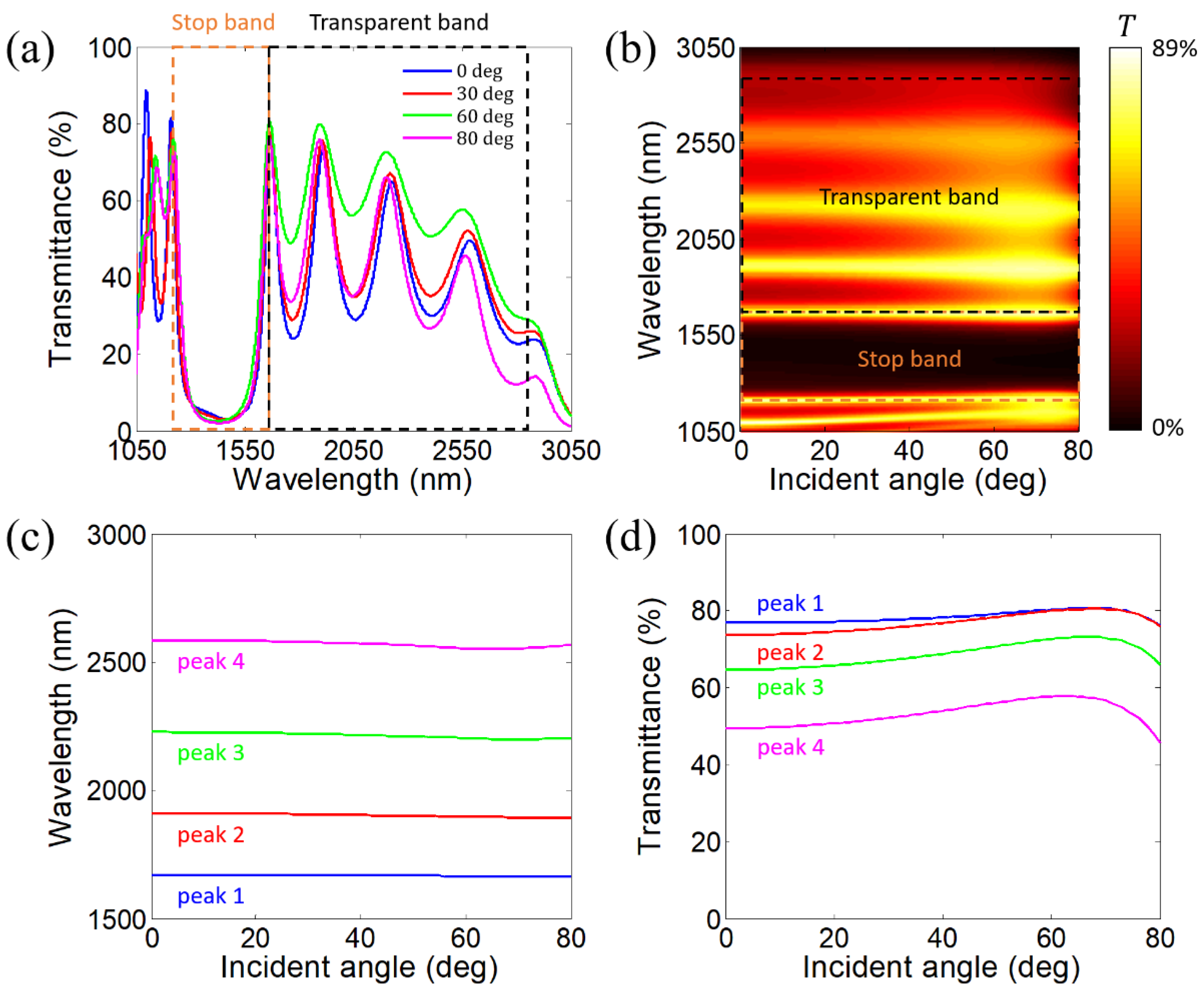
2. Angle-Dispersion-Free Near-Infrared Transparent Bands in 1-D PHCs

In this section, we realize an angle-dispersion-free transparent band adjacent to an angle-dispersion-free stop band in a 1-D PHC in the near-infrared range under p-polarization. As schematically illustrated in Figure 1a, the designed 1-D PHC is constructed by alternating isotropic dielectric and HDMM layers (A and B layers). The temperature is set as the room temperature T = 300 K. The isotropic dielectric layers are silicon (Si) layers with a refractive index of nA = 3.48 [51]. The HDMM layers are realized by Si/indium tin oxide (ITO) subwavelength multilayers (CD)6. Notice that the angle-dispersion-free property of the stop band and transparent band can still be achieved when replacing the ITO layers with indium-doped cadmium oxide (In:CdO) layers in the 1-D PHC (details can be seen in Section 4.1). The designed 1-D PHC is represented as [A(CD)6]N. Owing to the axial symmetry of the 1-D PHC, the wavevector of the incident light can be constrained to the xOz plane. The designed 1-D PHC can be fabricated by the magnetic sputtering technique [52]. As a category of plasmonic materials, the relative permittivity of ITO is governed by the following Drude model [53]:
ε D = ε ω p 2 ω 2 + i ω Γ .
In Equation (1), ε , ω p , ω , and Γ characterize the high-frequency permittivity, the plasma angular frequency, the angular frequency of light, and the damping rate, respectively. The values of the parameters can be obtained as ε inf = 3.9 , ω p = 2.48   e V , and Γ = 0.016   e V through the fitting of the measured optical spectrum of the ITO thin film [53].
In the frame of the equivalent medium theory [54], the equivalent relative permittivity tensor of the Si/ITO subwavelength multilayer (CD)6 is represented as
ε B ̿ = ε B x 0 0 0 ε B x 0 0 0 ε B z ,
where
ε B x = p ε C + ( 1 p ) ε D ,
1 ε B z = p ε C + 1 p ε D .
In Equations (1) and (2), p = d C / ( d C + d D ) characterizes the duty cycle of Si inside the Si/ITO subwavelength multilayer (CD)6.
By putting the relative permittivity of the isotropic dielectric ( ε A ) into Maxwell’s equations, we arrive at the equation of the iso-frequency contour of the isotropic dielectric under p-polarization, i.e., [35]
k x 2 ε A + k A z 2 ε A = ( ω c ) 2 ,
where k x = ω sin θ / c characterizes the tangential component (x component) of the wavevector, ω characterizes the angular frequency of light, θ characterizes the incident angle, c characterizes the light speed in air, and k A z characterizes the normal component (z component) of the wavevector in isotropic dielectric A. Since ε A > 0 , the iso-frequency contour of the isotropic dielectric under p-polarization is a circle, as diagrammed in Figure 1b.
Similarly, by putting the equivalent relative permittivity tensor of the Si/ITO subwavelength multilayer ( ε B ̿ ) into the Maxwell’s equations, we arrive at the equation of the iso-frequency contour of the Si/ITO subwavelength multilayer under p-polarization, i.e., [35]
k x 2 ε B z + k B z 2 ε B x = ( ω c ) 2 ,
where k B z characterizes the normal component (z component) of the wavevector in the Si/ITO subwavelength multilayer. In the wavelength region where R e ε B x > 0 and R e ε B z < 0 are fulfilled, the iso-frequency contour of the Si/ITO subwavelength multilayer under p-polarization is a hyperbola, as diagrammed in Figure 1c. Hence, the Si/ITO subwavelength multilayer can be treated as a type-I HDMM in such wavelength range.
In our design, the duty cycle of Si inside the Si/ITO subwavelength multilayer (CD)6 is set as p = 0.6 . Notice that the angle-dispersion-free property of the stop band and transparent band can still be achieved when setting another value of the duty cycle of Si inside the Si/ITO subwavelength multilayer (CD)6 (details can be seen in Section 4.2). According to Equations (3) and (4), we obtain the variations in two components (x and z components) of the equivalent relative permittivity tensor of the Si/ITO subwavelength multilayer (CD)6 with the wavelength, as illustrated in Figure 2a. R e ε B x > 0 and R e ε B z < 0 are fulfilled in the wavelength region denoted by the orange-shadowed area. Therefore, the Si/ITO subwavelength multilayer (CD)6 can be treated as a type-I HDMM in the wavelength region from 989.4 to 1733.3 nm.
Following the Bragg scattering theory, the Bragg wavelength ( λ Brg ) of the longest-wavelength stop band in the 1-D PHC [A(CD)6]5 at the incident angle θ can be determined by [55]
Φ λ Brg , θ = Φ A λ Brg , θ + Φ B λ Brg , θ = π .
In Equation (7), Φ characterizes the total propagation phase of a unit cell, Φ A = k A z d A characterizes the propagation phase of the isotropic dielectric layer (A layer) with d A being the thickness of the isotropic dielectric layer (A layer), and Φ B = k B z d B characterizes the propagation phase of the HDMM layer (B layer) with d B being the thickness of the HDMM layer (B layer).
To realize an angle-dispersion-free stop band, the partial derivation of the total propagation phase of a unit cell with respective to the incident angle should be zero, i.e.,
Φ θ λ Brg = 0 .
Equation (8) yields
Φ A θ λ Brg = Φ B θ λ Brg .
Equation (9) can be called as the phase-variation compensation condition [43].
In the frame of the phase-variation compensation theory [43], under the approximation conditions ε A 1 and Re ( ε B z ) 1 , the thicknesses of the isotropic dielectric layer (A layer) and HDMM layer (B layer) for an angle-dispersion-free stop band should follow
d A = λ Brg 2 1 ε A [ 1 Re ( ε B z ) ε A ] ,
d B = λ Brg 2 1 ε B x [ 1 ε A Re ( ε B z ) ] .
According to Equations (10) and (11), we obtain the variations in the thicknesses of the isotropic dielectric layer (A layer) and HDMM layer (B layer) with the Bragg wavelength, as illustrated in Figure 2b. As the Bragg wavelength goes up from 1200 to 1600 nm, the thickness of the isotropic dielectric layer (A layer) decreases from 115.70 to 33.80 nm while the thickness of the HDMM layer (B layer) increases from 77.24 to 313.17 nm. Herein, the Bragg wavelength is chosen as λ Brg = 1390   n m . The thicknesses of the isotropic dielectric layer (A layer) and HDMM layer (B layer) can be obtained as d A = 80.66   n m and d B = 172.82   n m , respectively. Since p = 0.6 , the thicknesses of the Si and ITO layers inside the HDMM layer can be obtained as d C = p d B / 6 = 17.28   n m and d D = ( 1 p ) d B / 6 = 11.52   n m , respectively.
Herein, we set the number of periods in the 1-D PHC as N = 5. Notice that the angle-dispersion-free property of the stop band and transparent band can still be achieved when setting another value of the number of periods in the 1-D PHC (details can be seen in Section 4.3). The results in Section 4.3 show that as the number of periods becomes larger, the bandwidth of the transparent band becomes larger and the transmittance peaks within the transparent band become sharper. However, when the number of periods increases from N = 4 to N = 6, the longest-wavelength transmittance peak becomes blurred at some incident angles (e.g., 60°) due to the large optical absorption at the long-wavelength region caused by ITO layers. This is the reason why we set the number of periods in the 1-D PHC as N = 5. Following the transfer matrix method [56], we calculate the transmittance spectra of the 1-D PHC [A(CD)6]5 at four incident angles, 0°, 30°, 60°, and 80°, under p-polarization, as illustrated in Figure 3a. As illustrated, an angle-dispersion-free stop band appears around the Bragg wavelength λ Brg = 1390   n m . Adjacent to the angle-dispersion-free stop band, an angle-dispersion-free transparent band appears. The angle-dispersion-free property of the transparent band can be explained as follows. The angle-dispersion-free property of the short-wavelength edge of the transparent band originates from the angle-dispersion-free property of the stop band. The angle-dispersion-free property of the long-wavelength edge of the transparent band originates from the angle-dispersion-free property of the band edge with zero volume-averaged permittivity ( ε ¯ = 0 at λ = 3016.20   n m ) [57]. At normal incidence, four transmittance peaks (peaks 1–4) within the transparent band are located at 1711.4, 2030.5, 2440.8, and 2839.1 nm, respectively. The transmittance peaks within the transparent band originate from the multiple interference mechanism [7,32]. These modes belong to resonant modes within the transparent band. The simulated magnetic field distributions at the wavelengths of four transmittance peaks within the transparent band can be seen in Section 4.4. We define the wavelength range between peaks 1 and 4 as the transparent band. The transparent band spans from 1711.4 to 2839.1 nm with a bandwidth of 1127.7 nm. The peak values of four transmittance peaks are 80.4%, 74.8%, 61.9%, and 35.8%, respectively. As the wavelength of the transmittance peak increases, the peak value of the transmittance peak decreases. The underlying reason is that the plasmonic property of ITO becomes stronger as the wavelength increases. To confirm the accuracy of the transfer matrix method, we perform the full-wave simulations via the COMSOL Multiphysics 6.0 software and obtain the transmittance spectra of the 1-D PHC [A(CD)6]5 at four incident angles, 0°, 30°, 60°, and 80°, under p-polarization, as illustrated in Figure 3b. Clearly, the simulated transmittance spectra agree well with the calculated ones. Specifically, at normal incidence, four transmittance peaks (peaks 1–4) within the transparent band are located at 1710.5, 2028.9, 2437.9, and 2834.4 nm, respectively. The transparent band spans from 1710.5 to 2834.4 nm with a bandwidth of 1123.9 nm. The peak values of four transmittance peaks are 80.3%, 74.6%, 61.8%, and 35.6%, respectively. To confirm the angle-dispersion-free property of the transparent band, we calculate the variation in the transmittance spectrum of the 1-D PHC [A(CD)6]5 with the incident angle under p-polarization based on the transfer matrix method, as illustrated in Figure 3c. Clearly, the transparent band exhibits a superior angle-dispersion-free property. Notice that the angle-dispersion-free transparent band in the 1-D PHC can only be realized under p-polarization since the iso-frequency contour of the HDMM realized by the Si/ITO subwavelength multilayer (CD)6 is a circle under s-polarization [35], which is the same as those of the isotropic dielectrics.
Then, we calculate the variations in the wavelengths of four transmittance peaks within the transparent band with the incident angle, as illustrated in Figure 4a. As the incident angle increases from 0° to 80°, the wavelength of peak 1 marginally decreases from 1711.4 to 1703.4 nm. The wavelength of peak 2 marginally decreases from 2030.5 to 2007.2 nm and then marginally increases to 2009.1 nm. The wavelength of peak 3 marginally decreases from 2440.8 to 2405.5 nm and then marginally increases to 2416.7 nm. The wavelength of peak 4 marginally decreases from 2839.1 to 2803.4 nm and then marginally increases to 2835.9 nm. The relative shifts of the wavelengths of peaks 1–4 are only 0.47%, 1.16%, 1.47%, and 1.27%, respectively. As the incident angle increases from 0° to 80°, the bandwidth of the transparent band marginally decreases from 1127.7 to 1098.2 nm and then marginally increases from 1132.5 nm. Moreover, we calculate the variations in the peak values of four transmittance peaks within the transparent band with the incident angle, as illustrated in Figure 4b. As the incident angle increases from 0° to 80°, the peak value of peak 1 goes up from 80.4% to 84.5% and subsequently goes down to 80.6%. The peak value of peak 2 goes up from 74.8% to 81.6% and subsequently goes down to 76.8%. The peak value of peak 3 goes up from 61.9% to 70.1% and subsequently goes down to 60.9%. The peak value of peak 4 goes up from 35.8% to 42.3% and subsequently goes down to 25.4%.
Next, we consider the thermo-optical effect and investigate the impact of the temperature on the angle-dispersion-free property of the near-infrared transparent band (details can be seen in Section 4.5). The results show that the angle-dispersion-free property of the near-infrared transparent band can be maintained in the temperature range from 300 to 600 K.
Finally, we give the comparison of the performance of the angle-dispersion-free transparent band between our work and the reported works [58,59,60], as given in Table 1. Clearly, the relative bandwidth of the angle-dispersion-free transparent band in our work is much larger than those in the reported works [58,59,60]. Moreover, the structure proposed in our work is a 1-D structure, whose fabrication process does not require the lithography technique. However, the structures proposed in Refs. [58,59,60] are 2-D or 3-D structures, whose fabrication process requires the lithography technique. In other words, the fabrication of the structure proposed in our work is simpler and lower in cost.

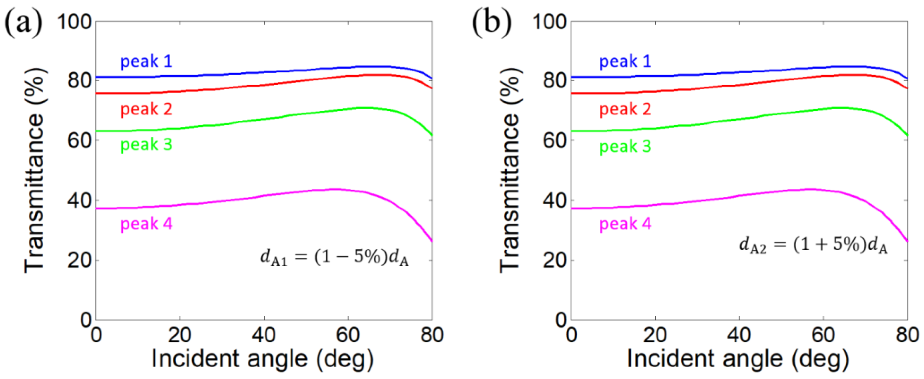
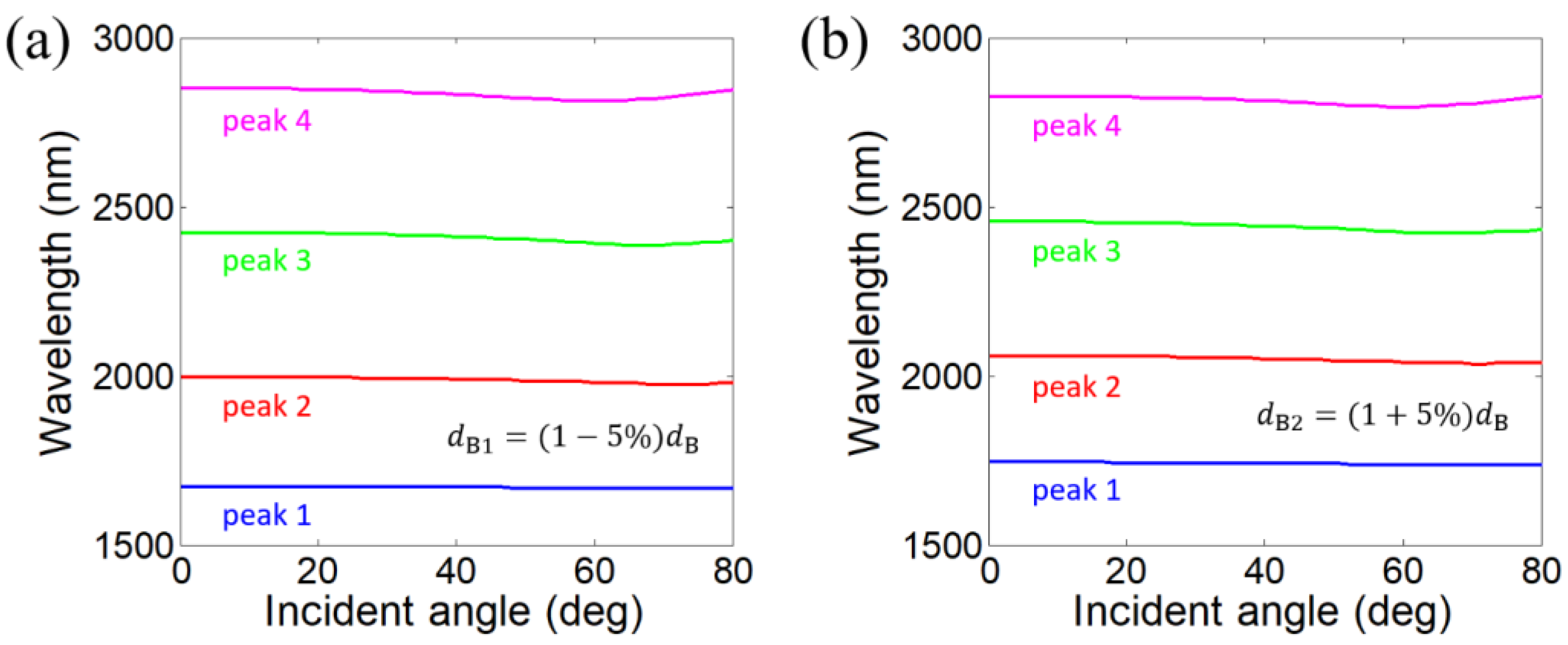
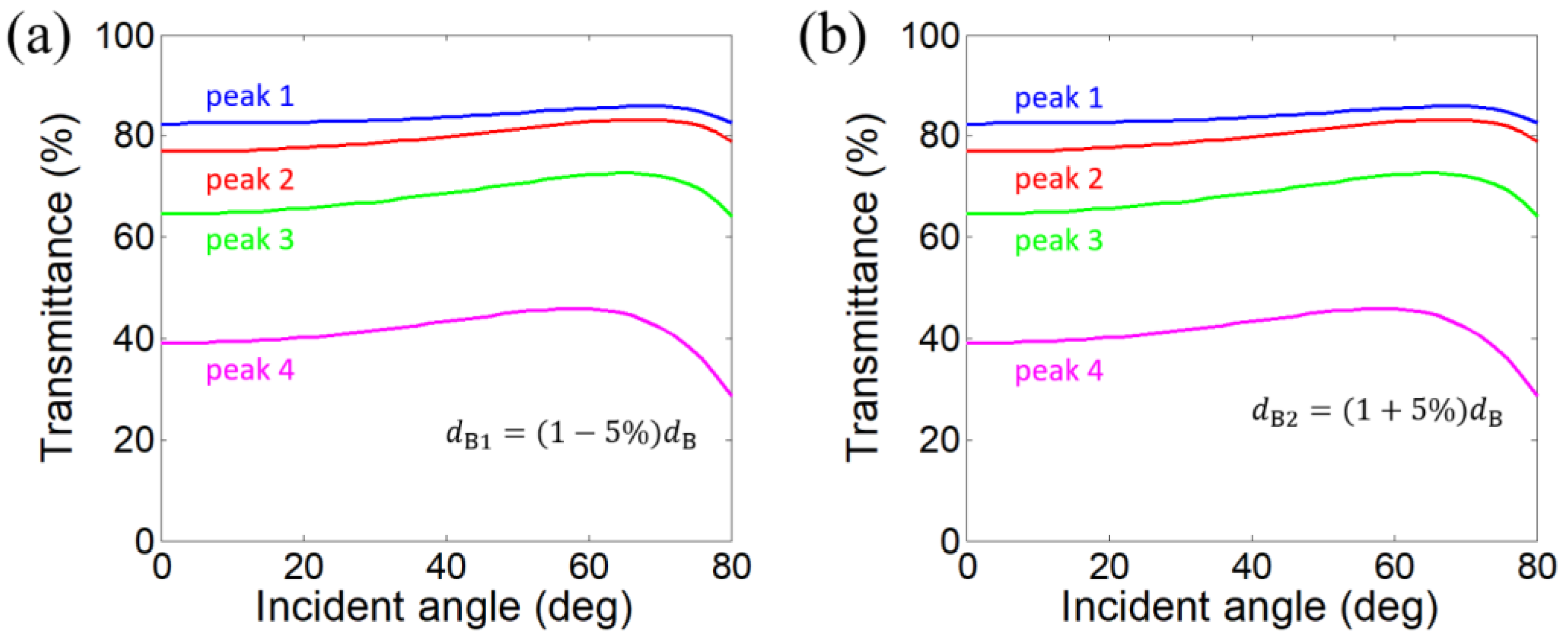
3. Impacts of Layer Thickness Disturbance on the Angle-Dispersion-Free Property of Near-Infrared Transparent Bands

It is known that in practical fabrication, there are certain deviations between the actual thickness and the designed thickness of each layer in 1-D PHCs. Hence, it is essential to investigate the impacts of the layer thickness disturbance on the angle-dispersion-free property of the transparent band.
Firstly, we investigate the impact of the thickness disturbance of the isotropic dielectric layer (A layer) on the angle-dispersion-free property of the transparent band. We reduce the thickness of the isotropic dielectric layer (A layer) by 5%, i.e., d A 1 = ( 1 5 % ) d A = 76.62   n m and calculate the variations in the wavelengths of four transmittance peaks within the transparent band with the incident angle, as illustrated in Figure 5a. As the incident angle increases from 0° to 80°, the wavelength of peak 1 marginally decreases from 1681.9 to 1675.8 nm. The wavelength of peak 2 marginally decreases from 1998.8 to 1976.6 nm and then marginally increases to 1978.7 nm. The wavelength of peak 3 marginally decreases from 2406.8 to 2371.8 nm and then marginally increases to 2383.5 nm. The wavelength of peak 4 marginally decreases from 2804.2 to 2768.2 nm and then marginally increases to 2802.2 nm. The relative shifts of the wavelengths of peaks 1–4 are only 0.36%, 1.12%, 1.48%, and 1.30%, respectively. As the incident angle increases from 0° to 80°, the bandwidth of the transparent band marginally decreases from 1122.3 to 1091.0 nm and then marginally increases to 1126.4 nm. Then, we augment the thickness of the isotropic dielectric layer (A layer) by 5%, i.e., d A 2 = ( 1 + 5 % ) d A = 84.69   n m and calculate the variations in the wavelengths of four transmittance peaks within the transparent band with the incident angle, as illustrated in Figure 5b. As the incident angle increases from 0° to 80°, the wavelength of peak 1 marginally decreases from 1740.9 to 1731.0 nm. The wavelength of peak 2 marginally decreases from 2062.2 to 2037.7 nm and then marginally increases to 2039.4 nm. The wavelength of peak 3 marginally decreases from 2474.8 to 2439.0 nm and then marginally increases to 2449.7 nm. The wavelength of peak 4 marginally decreases from 2873.9 to 2838.1 nm and then marginally increases to 2869.4 nm. The relative shifts of the wavelengths of peaks 1–4 are only 0.57%, 1.20%, 1.47%, and 1.26%, respectively. As the incident angle increases from 0° to 80°, the bandwidth of the transparent band marginally decreases from 1133.0 to 1105.0 nm and then marginally increases to 1138.4 nm.
Furthermore, Figure 6a and Figure 6b give the variations in the peak values of four transmittance peaks within the transparent band with the incident angle when the thicknesses of the isotropic dielectric layer (A layer) are d A 1 = 1 5 % d A = 76.62   n m and d A 2 = ( 1 + 5 % ) d A = 84.69   n m , respectively. In the case of d A 1 = 1 5 % d A = 76.62   n m , as the incident angle increases from 0° to 80°, the peak value of peak 1 goes up from 81.3% to 84.9% and subsequently goes down to 80.9%. The peak value of peak 2 goes up from 75.6% to 82.0% and subsequently goes down to 77.2%. The peak value of peak 3 goes up from 63.0% to 70.8% and subsequently goes down to 61.6%. The peak value of peak 4 goes up from 37.3% to 43.6% and subsequently goes down to 26.1%. In the case of d A 2 = ( 1 + 5 % ) d A = 84.69   n m , as the incident angle increases from 0° to 80°, the peak value of peak 1 goes up from 79.5% to 84.1% and subsequently goes down to 80.4%. The peak value of peak 2 goes up from 73.9% to 81.1% and subsequently goes down to 76.4%. The peak value of peak 3 goes up from 60.8% to 69.3% and subsequently goes down to 60.2%. The peak value of peak 4 goes up from 34.4% to 41.1% and subsequently goes down to 24.7%. Therefore, the angle-dispersion-free property of the transparent band is robust when the thickness of the isotropic dielectric layer (A layer) is changed by ±5%.
Secondly, we investigate the impact of the thickness disturbance of the HDMM layer (B layer) on the angle-dispersion-free property of the transparent band. We reduce the thickness of the HDMM layer (B layer) by 5%, i.e., d B 1 = ( 1 5 % ) d B = 164.17   n m and calculate the variations in the wavelengths of four transmittance peaks within the transparent band with the incident angle, as illustrated in Figure 7a. In this case, the thicknesses of the Si and ITO layers inside the HDMM layer are obtained as d C 1 = p d B 1 / 6 = 16.42   n m and d D 1 = ( 1 p ) d B 1 / 6 = 10.94   n m , respectively. As the incident angle increases from 0° to 80°, the wavelength of peak 1 marginally decreases from 1675.1 to 1668.2 nm. The wavelength of peak 2 marginally decreases from 1999.4 to 1975.8 nm and then marginally increases to 1977.8 nm. The wavelength of peak 3 marginally decreases from 2424.7 to 2387.2 nm and then marginally increases to 2399.1 nm. The wavelength of peak 4 marginally decreases from 2850.4 to 2811.4 nm and then marginally increases to 2846.0 nm. The relative shifts of the wavelengths of peaks 1–4 are only 0.41%, 1.19%, 1.57%, and 1.39%, respectively. As the incident angle increases from 0° to 80°, the bandwidth of the transparent band marginally decreases from 1175.3 to 1141.6 nm and then marginally increases to 1177.8 nm. Then, we augment the thickness of the HDMM layer (B layer) by 5%, i.e., d B 2 = ( 1 + 5 % ) d B = 181.46   n m and calculate the variations in the wavelengths of four transmittance peaks within the transparent band with the incident angle, as illustrated in Figure 7b. In this case, the thicknesses of the Si and ITO layers inside the HDMM layer are obtained as d C 2 = p d B 2 / 6 = 18.15   n m and d D 2 = ( 1 p ) d B 2 / 6 = 12.10   n m , respectively. As the incident angle increases from 0° to 80°, the wavelength of peak 1 marginally decreases from 1746.3 to 1737.2 nm. The wavelength of peak 2 marginally decreases from 2059.8 to 2036.8 nm and then marginally increases to 2038.6 nm. The wavelength of peak 3 marginally decreases from 2455.4 to 2422.0 nm and then marginally increases to 2432.6 nm. The wavelength of peak 4 marginally decreases from 2828.3 to 2795.1 nm and then marginally increases to 2826.0 nm. The relative shifts of the wavelengths of peaks 1–4 are only 0.52%, 1.13%, 1.37%, and 1.19%, respectively. As the incident angle increases from 0° to 80°, the bandwidth of the transparent band marginally decreases from 1082.0 to 1055.8 nm and then marginally increases to 1088.8 nm.
Furthermore, Figure 8a and Figure 8b give the variations in the peak values of four transmittance peaks within the transparent band with the incident angle when the thicknesses of the HDMM layer (B layer) are d B 1 = ( 1 5 % ) d B = 164.17   n m and d B 2 = ( 1 + 5 % ) d B = 181.46   n m , respectively. In the case of d B 1 = ( 1 5 % ) d B = 164.17   n m , as the incident angle increases from 0° to 80°, the peak value of peak 1 goes up from 82.4% to 85.9% and subsequently goes down to 82.4%. The peak value of peak 2 goes up from 76.9% to 83.3% and subsequently goes down to 79.0%. The peak value of peak 3 goes up from 64.6% to 72.6% and subsequently goes down to 64.2%. The peak value of peak 4 goes up from 39.1% to 45.8% and subsequently goes down to 28.6%. In the case of d B 2 = ( 1 + 5 % ) d B = 181.46   n m , as the incident angle increases from 0° to 80°, the peak value of peak 1 goes up from 78.4% to 83.0% and subsequently goes down to 78.7%. The peak value of peak 2 goes up from 72.6% to 79.7% and subsequently goes down to 74.4%. The peak value of peak 3 goes up from 59.2% to 67.4% and subsequently goes down to 57.6%. The peak value of peak 4 goes up from 32.7% to 38.9% and subsequently goes down to 22.5%. Therefore, the angle-dispersion-free property of the transparent band is robust when the thickness of the HDMM layer (B layer) is changed by ±5%.
Finally, we perform the robustness analysis with ±80% thickness variation with a step of 1%. We set a relative shift of 2% as the threshold. When the relative shifts of all the transmittance peaks within the transparent band are smaller than 2%, the transparent band is defined as an angle-dispersion-free transparent band. When the relative shift of one of the transmittance peaks within the transparent band is larger than 2%, the transparent band is defined as an angle-dispersive transparent band. When changing the thickness of the isotropic dielectric layer (A layer) and keeping the thickness of the HDMM layer (B layer) unchanged, the transparent band remains angle-dispersion-free when the thickness of the isotropic dielectric layer (A layer) is in the range of [ ( 1 59 % ) d A , ( 1 + 80 % ) d A ] . When changing the thickness of the HDMM layer (B layer) and keeping the thickness of the isotropic dielectric layer (A layer) unchanged, the transparent band remains angle-dispersion-free when the thickness of the HDMM layer (B layer) is in the range of [ ( 1 21 % ) d B , ( 1 + 80 % ) d B ] . Hence, the angle-dispersion-free property of the transparent band is quite robust against the layer thickness disturbance.

4. Discussion

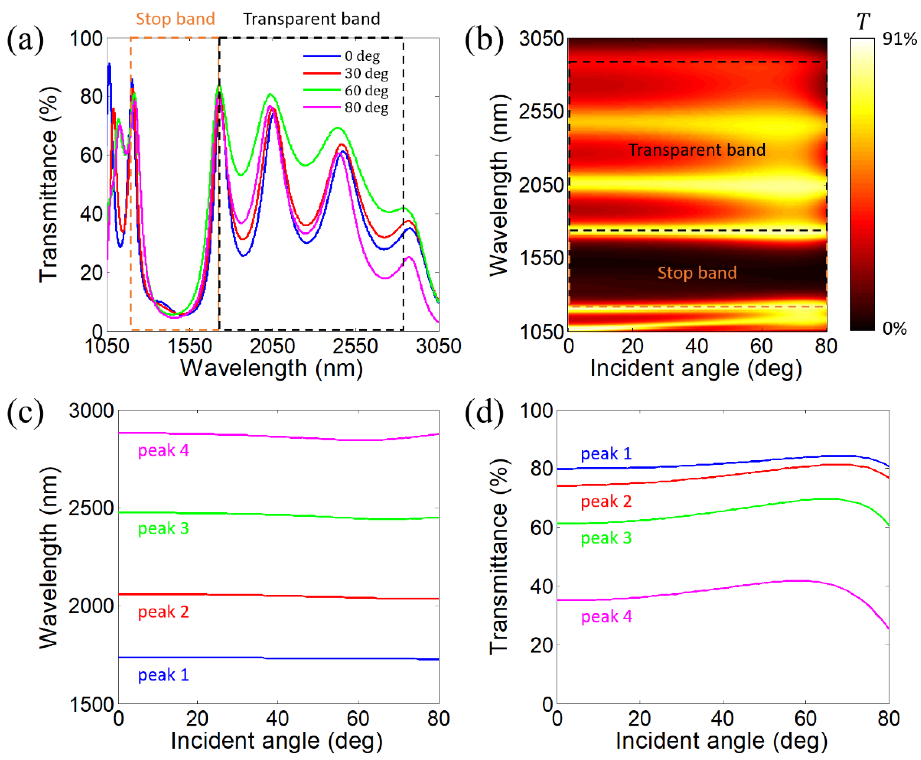
4.1. Angle-Dispersion-Free Near-Infrared Stop Bands and Transparent Bands in 1-D PHCs Constructed by Alternating Si Layers and HDMM Layers Realized by Si/In:CdO Subwavelength Multilayers (CD)6

It this subsection, we replace the ITO layers with In:CdO layers in the 1-D PHC to realize the angle-dispersion-free stop band and transparent band. The new 1-D PHC can be denoted by [A(CD)6]4. The material of D layers is changed to In:CdO while the materials of A and C layers remain Si. As a category of plasmonic materials, the relative permittivity of In:CdO is governed by the following Drude model [61].
ε D = ε ω p 2 ω 2 + i ω Γ .
In Equation (12), ε , ω p , ω , and Γ characterize the high-frequency permittivity, the plasma angular frequency, the angular frequency of light, and the damping rate, respectively. The values of the parameters can be obtained as ε inf = 5.5 , ω p = 1.3907   e V , and Γ = 0.0193   e V through the fitting of the measured optical spectrum of the In:CdO thin film [61].
Then, the duty cycle of Si inside the Si/In:CdO subwavelength multilayer (CD)6 is set as p = 0.2 . According to Equations (3) and (4), we obtain the variations in two components (x and z components) of the equivalent relative permittivity tensor of the Si/In:CdO subwavelength multilayer (CD)6 with the wavelength, as illustrated in Figure 9. R e ε B x > 0 and R e ε B z < 0 are fulfilled in the wavelength region denoted by the orange-shadowed area. Therefore, the Si/In:CdO subwavelength multilayer (CD)6 can be treated as a type-I HDMM in the wavelength region from 2096.3 to 2611.0 nm.
In our design, the Bragg wavelength is chosen as λ B r g = 2430   n m . According to Equations (10) and (11), the thicknesses of the isotropic dielectric layer (A layer) and HDMM layer (B layer) can be obtained as d A = 290.31   n m and d B = 214.46   n m , respectively. Since p = 0.2 , the thicknesses of the Si and ITO layers inside the HDMM layer can be obtained as d C = p d B / 6 = 7.15   n m and d D = ( 1 p ) d B / 6 = 28.60   n m , respectively. Following the transfer matrix method [56], we calculate the transmittance spectra of the 1-D PHC [A(CD)6]4 at four incident angles, 0°, 30°, 60°, and 80°, under p-polarization, as illustrated in Figure 10a. As illustrated, an angle-dispersion-free stop band appears around the Bragg wavelength λ B r g = 2430   n m . Adjacent to the angle-dispersion-free stop band, an angle-dispersion-free transparent band appears. At normal incidence, three transmittance peaks (peaks 1–3) within the transparent band are located at 3543.7, 4169.5, and 4833.5 nm, respectively. We define the wavelength range between peaks 1 and 3 as the transparent band. The transparent band spans from 3543.7 to 4833.5 nm with a bandwidth of 1289.8 nm. The peak values of three transmittance peaks are 41.1%, 30.7%, and 9.8%, respectively. To confirm the angle-dispersion-free property of the transparent band, we calculate the variation in the transmittance spectrum of the 1-D PHC [A(CD)6]4 with the incident angle under p-polarization, as illustrated in Figure 10b. Clearly, the transparent band exhibits a superior angle-dispersion-free property. Next, we calculate the variations in the wavelengths of three transmittance peaks within the transparent band with the incident angle, as illustrated in Figure 10c. As the incident angle increases from 0° to 80°, the wavelength of peak 1 marginally increases from 3543.7 to 3548.6 nm and then marginally decreases to 3548.2 nm. The wavelength of peak 2 marginally decreases from 4169.5 to 4127.4 nm and then marginally increases to 4130.6 nm. The wavelength of peak 3 marginally decreases from 4833.5 to 4737.4 nm and then marginally increases to 4766.6 nm. The relative shifts of the wavelengths of peaks 1–3 are only 0.14%, 1.02%, and 2.03%, respectively. As the incident angle increases from 0° to 80°, the bandwidth of the transparent band marginally decreases from 1289.8 to 1188.7 nm and then marginally increases from 1218.5 nm. Moreover, we calculate the variations in the peak values of three transmittance peaks within the transparent band with the incident angle, as illustrated in Figure 10d. As the incident angle increases from 0° to 80°, the peak value of peak 1 goes up from 41.1% to 55.7% and subsequently goes down to 54.3%. The peak value of peak 2 goes up from 30.7% to 47.0% and subsequently goes down to 43.3%. The peak value of peak 3 goes up from 9.8% to 18.8% and subsequently goes down to 14.1%. To sum up, the angle-dispersion-free transparent band in the 1-D PHC can still be achieved when replacing ITO with In:CdO layers in the 1-D PHC.

4.2. Impact of Duty Cycle of Si Inside the Si/ITO Subwavelength Multilayer (CD)6 on the Angle-Dispersion-Free Property of the Near-Infrared Transparent Band

In this subsection, we change the duty cycle of Si inside the Si/ITO subwavelength multilayer (CD)6 to p = 0.55 and p = 0.65 and investigate the corresponding impacts on the angle-dispersion-free property of the near-infrared transparent band. Firstly, we decrease the duty cycle of Si to p = 0.55 . According to Equations (3) and (4), we obtain the variations in two components (x and z components) of the equivalent relative permittivity tensor of the Si/ITO subwavelength multilayer (CD)6 with the wavelength, as illustrated in Figure 11. R e ε B x > 0 and R e ε B z < 0 are fulfilled in the wavelength region denoted by the orange-shadowed area. Therefore, the Si/ITO subwavelength multilayer (CD)6 can be treated as a type-I HDMM in the wavelength region from 989.4 to 1861.3 nm.
Herein, the Bragg wavelength remains unchanged, i.e., λ B r g = 1390   n m . According to Equations (10) and (11), the thicknesses of the isotropic dielectric layer (A layer) and HDMM layer (B layer) can be obtained as d A = 93.86   n m and d B = 165.53   n m , respectively. Since p = 0.55 , the thicknesses of the Si and ITO layers inside the HDMM layer can be obtained as d C = p d B / 6 = 15.17   n m and d D = ( 1 p ) d B / 6 = 12.42   n m , respectively. Following the transfer matrix method [56], we calculate the transmittance spectra of the 1-D PHC [A(CD)6]5 at four incident angles, 0°, 30°, 60°, and 80°, under p-polarization, as illustrated in Figure 12a. As illustrated, an angle-dispersion-free stop band appears around the Bragg wavelength λ B r g = 1390   n m . Adjacent to the angle-dispersion-free stop band, an angle-dispersion-free transparent band appears. At normal incidence, four transmittance peaks (peaks 1–4) within the transparent band are located at 1738.1, 2039.7, 2425.7, and 2794.0 nm, respectively. We define the wavelength range between peaks 1 and 4 as the transparent band. The transparent band spans from 1738.1 to 2794.0 nm with a bandwidth of 1055.9 nm. The peak values of four transmittance peaks are 76.1%, 71.3%, 57.6%, and 30.1%, respectively. To confirm the angle-dispersion-free property of the stop band and the transparent band, we calculate the variation in the transmittance spectrum of the 1-D PHC [A(CD)6]5 with the incident angle under p-polarization, as illustrated in Figure 12b. Clearly, the transparent band exhibits a superior angle-dispersion-free property. Then, we calculate the variations in the wavelengths of four transmittance peaks within the transparent band with the incident angle, as illustrated in Figure 12c. As the incident angle increases from 0° to 80°, the wavelength of peak 1 marginally decreases from 1738.1 to 1732.7 nm. The wavelength of peak 2 marginally decreases from 2039.7 to 2019.8 nm and then marginally increases to 2020.7 nm. The wavelength of peak 3 marginally decreases from 2425.7 to 2396.5 nm and then marginally increases to 2403.5 nm. The wavelength of peak 4 marginally decreases from 2794.0 to 2766.3 nm and then marginally increases to 2787.0 nm. The relative shifts of the wavelengths of peaks 1–4 are only 0.31%, 0.99%, 1.22%, and 1.00%, respectively. As the incident angle increases from 0° to 80°, the bandwidth of the transparent band marginally decreases from 1055.9 to 1032.4 nm and then marginally increases from 1054.3 nm. Moreover, we calculate the variations in the peak values of four transmittance peaks within the transparent band with the incident angle, as illustrated in Figure 12d. As the incident angle increases from 0° to 80°, the peak value of peak 1 goes up from 76.1% to 81.3% and subsequently goes down to 77.6%. The peak value of peak 2 goes up from 71.3% to 79.2% and subsequently goes down to 74.4%. The peak value of peak 3 goes up from 57.6% to 66.7% and subsequently goes down to 57.7%. The peak value of peak 4 goes up from 30.1% to 37.1% and subsequently goes down to 22.5%. To sum up, when the duty cycle is decreased to p = 0.55 , the relative shifts of the wavelengths of four transmittance peaks within the transparent band are smaller than 1.5%, indicating that the angle-dispersion-free property of the transparent band can still be achieved.
Secondly, we increase the duty cycle of Si to p = 0.65 . According to Equations (3) and (4), we obtain the variations in two components (x and z components) of the equivalent relative permittivity tensor of the Si/ITO subwavelength multilayer (CD)6 with the wavelength, as illustrated in Figure 13. R e ε B x > 0 and R e ε B z < 0 are fulfilled in the wavelength region denoted by the orange-shadowed area. Therefore, the Si/ITO subwavelength multilayer (CD)6 can be treated as a type-I HDMM in the wavelength region from 989.4 to 1617.0 nm.
Herein, the Bragg wavelength remains unchanged, i.e., λ B r g = 1390   n m . According to Equations (10) and (11), the thicknesses of the isotropic dielectric layer (A layer) and HDMM layer (B layer) can be obtained as d A = 63.72   n m and d B = 185.02   n m , respectively. Since p = 0.65 , the thicknesses of the Si and ITO layers inside the HDMM layer can be obtained as d C = p d B / 6 = 20.04   n m and d D = ( 1 p ) d B / 6 = 10.79   n m , respectively. Following the transfer matrix method [56], we calculate the transmittance spectra of the 1-D PHC [A(CD)6]5 at four incident angles, 0°, 30°, 60°, and 80°, under p-polarization, as illustrated in Figure 14a. As illustrated, an angle-dispersion-free stop band appears around the Bragg wavelength λ B r g = 1390   n m . Adjacent to the angle-dispersion-free stop band, an angle-dispersion-free transparent band appears. At normal incidence, four transmittance peaks (peaks 1–4) within the transparent band are located at 1688.0, 2022.6, 2453.8, and 2875.5 nm, respectively. We define the wavelength range between peaks 1 and 4 as the transparent band. The transparent band spans from 1688.0 to 2875.5 nm with a bandwidth of 1187.6 nm. The peak values of four transmittance peaks are 83.8%, 77.5%, 65.5%, and 41.4%, respectively. To confirm the angle-dispersion-free property of the stop band and the transparent band, we calculate the variation in the transmittance spectrum of the 1-D PHC [A(CD)6]5 with the incident angle under p-polarization, as illustrated in Figure 14b. Clearly, the transparent band exhibits a superior angle-dispersion-free property. Then, we calculate the variations in the wavelengths of four transmittance peaks within the transparent band with the incident angle, as illustrated in Figure 14c. As the incident angle increases from 0° to 80°, the wavelength of peak 1 marginally decreases from 1688.0 to 1677.1 nm. The wavelength of peak 2 marginally decreases from 2022.6 to 1994.6 nm and then marginally increases to 1998.8 nm. The wavelength of peak 3 marginally decreases from 2453.8 to 2408.1 nm and then marginally increases to 2427.8 nm. The wavelength of peak 4 marginally decreases from 2875.5 to 2814.6 nm and then marginally increases to 2879.1 nm. The relative shifts of the wavelengths of peaks 1–4 are only 0.64%, 1.40%, 1.90%, and 2.29%, respectively. As the incident angle increases from 0° to 80°, the bandwidth of the transparent band marginally decreases from 1187.6 to 1135.0 nm and then marginally increases to 1202.0 nm. Moreover, we calculate the variations in the peak values of four transmittance peaks within the transparent band with the incident angle, as illustrated in Figure 14d. As the incident angle increases from 0° to 80°, the peak value of peak 1 goes up from 83.8% to 87.0% and subsequently goes down to 83.1%. The peak value of peak 2 goes up from 77.5% to 83.5% and subsequently goes down to 78.7%. The peak value of peak 3 goes up from 65.5% to 72.8% and subsequently goes down to 63.5%. The peak value of peak 4 goes up from 41.4% to 47.6% and subsequently goes down to 27.9%. To sum up, when the duty cycle is decreased to p = 0.65 , the relative shifts of the wavelengths of four transmittance peaks within the transparent band are smaller than 2.5%, indicating that the angle-dispersion-free property of the transparent band can still be achieved.

4.3. Impact of the Number of Periods in 1-D PHC on the Angle-Dispersion-Free Property of the Near-Infrared Transparent Band

In this subsection, we change the number of periods in the 1-D PHC N = 4 and N = 6 and investigate the corresponding impacts on the angle-dispersion-free property of the near-infrared transparent band. Firstly, we decrease the number of periods to N = 4 while keeping the other parameters unchanged. Following the transfer matrix method [56], we calculate the transmittance spectra of the 1-D PHC [A(CD)6]4 at four incident angles, 0°, 30°, 60°, and 80°, under p-polarization, as illustrated in Figure 15a. As illustrated, an angle-dispersion-free stop band appears around the Bragg wavelength λ B r g = 1390   n m . Adjacent to the angle-dispersion-free stop band, an angle-dispersion-free transparent band appears. The transparent band contains three transmittance peaks. At normal incidence, three transmittance peaks (peaks 1–3) within the transparent band are located at 1780.8, 2226.5, and 2750.9 nm, respectively. We define the wavelength range between peaks 1 and 3 as the transparent band. The transparent band spans from 1780.8 to 2750.9 nm with a bandwidth of 970.1 nm. The peak values of three transmittance peaks are 83.4%, 74.4%, and 51.6%, respectively. To confirm the angle-dispersion-free property of the stop band and the transparent band, we calculate the variation in the transmittance spectrum of the 1-D PHC [A(CD)6]4 with the incident angle under p-polarization, as illustrated in Figure 15b. Clearly, the transparent band exhibits a superior angle-dispersion-free property. Then, we calculate the variations in the wavelengths of three transmittance peaks within the transparent band with the incident angle, as illustrated in Figure 15c. As the incident angle increases from 0° to 80°, the wavelength of peak 1 marginally decreases from 1780.8 to 1768.5 nm. The wavelength of peak 2 marginally decreases from 2226.5 to 2194.5 nm and then marginally increases to 2201.5 nm. The wavelength of peak 3 marginally decreases from 2750.9 to 2711.1 nm and then marginally increases to 2739.0 nm. The relative shifts of the wavelengths of peaks 1–3 are only 0.69%, 1.46%, and 1.47%, respectively. As the incident angle increases from 0° to 80°, the bandwidth of the transparent band marginally decreases from 970.1 to 940.6 nm and then marginally increases to 970.5 nm. Moreover, we calculate the variations in the peak values of three transmittance peaks within the transparent band with the incident angle, as illustrated in Figure 15d. As the incident angle increases from 0° to 80°, the peak value of peak 1 goes up from 83.4% to 87.5% and subsequently goes down to 84.3%. The peak value of peak 2 goes up from 74.4% to 81.2% and subsequently goes down to 75.6%. The peak value of peak 3 goes up from 51.6% to 58.9% and subsequently goes down to 43.4%. To sum up, when the number of periods is N = 4, the relative shifts of the wavelengths of three transmittance peaks within the transparent band are smaller than 1.5%, indicating that the angle-dispersion-free property of the transparent band can still be achieved.
Secondly, we increase the number of periods to N = 6 while keeping the other parameters unchanged. Following the transfer matrix method [56], we calculate the transmittance spectra of the 1-D PHC [A(CD)6]6 at four incident angles, 0°, 30°, 60°, and 80°, under p-polarization, as illustrated in Figure 16a. As illustrated, an angle-dispersion-free stop band appears around the Bragg wavelength λ B r g = 1390   n m . Adjacent to the angle-dispersion-free stop band, an angle-dispersion-free transparent band appears. At normal incidence, the transparent band contains five transmittance peaks. At normal incidence, five transmittance peaks (peaks 1–5) within the transparent band are located at 1669.6, 1912.5, 2227.6, 2586.5, and 2884.4 nm, respectively. We define the wavelength range between peaks 1 and 5 as the transparent band. The transparent band spans from 1669.6 to 2884.4 nm with a bandwidth of 1214.8 nm. The peak values of five transmittance peaks are 77.0%, 73.8%, 64.7%, 49.5%, and 23.9%, respectively. However, owing to the large optical absorption at the long-wavelength region caused by ITO layers, the longest-wavelength transmittance peak becomes blurred at some incident angles (e.g., 60°) in the following. Hence, we focus on the first four transmittance peaks (peaks 1–4). To confirm the angle-dispersion-free property of the stop band and the transparent band, we calculate the variation in the transmittance spectrum of the 1-D PHC [A(CD)6]6 with the incident angle under p-polarization, as illustrated in Figure 16b. Clearly, the transparent band exhibits a superior angle-dispersion-free property. Then, we calculate the variations in the wavelengths of four transmittance peaks within the transparent band with the incident angle, as illustrated in Figure 16c. As the incident angle increases from 0° to 80°, the wavelength of peak 1 marginally decreases from 1669.6 to 1664.6 nm. The wavelength of peak 2 marginally decreases from 1912.5 to 1894.3 nm and then marginally increases to 1894.6 nm. The wavelength of peak 3 marginally decreases from 2227.6 to 2198.9 nm and then marginally increases to 2203.4 nm. The wavelength of peak 4 marginally decreases from 2586.5 to 2551.6 nm and then marginally increases to 2565.9 nm. The relative shifts of the wavelengths of peaks 1–4 are only 0.30%, 0.96%, 1.30%, and 1.37%, respectively. Moreover, we calculate the variations in the peak values of four transmittance peaks within the transparent band with the incident angle, as illustrated in Figure 16d. As the incident angle increases from 0° to 80°, the peak value of peak 1 goes up from 77.0% to 80.8% and subsequently goes down to 76.1%. The peak value of peak 2 goes up from 73.8% to 80.6% and subsequently goes down to 75.9%. The peak value of peak 3 goes up from 64.7% to 73.2% and subsequently goes down to 66.1%. The peak value of peak 4 goes up from 49.5% to 57.8% and subsequently goes down to 45.8%. To sum up, when the number of periods is N = 6, the relative shifts of the wavelengths of four transmittance peaks within the transparent band are smaller than 1.5%, indicating that the angle-dispersion-free property of the transparent band can still be achieved.

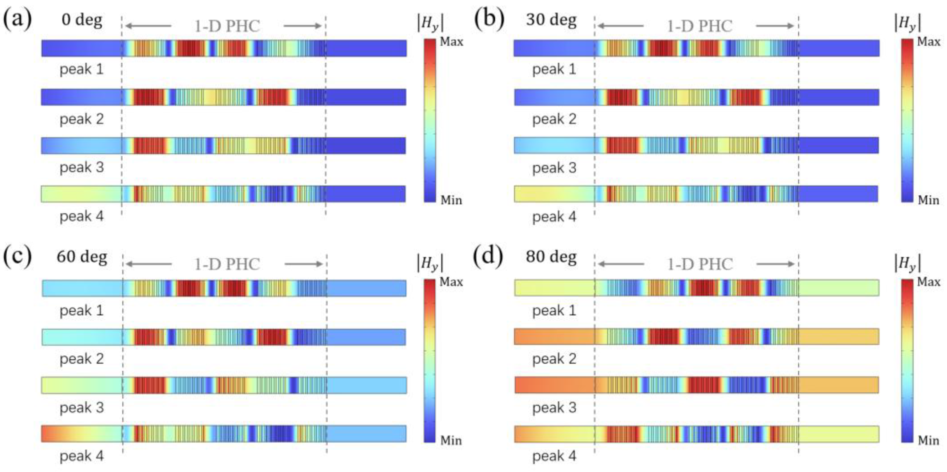
4.4. Simulated Magnetic Field Distributions at Wavelengths of Four Transmittance Peaks Within the Transparent Band

Utilizing the COMSOL Multiphysics software, we perform the full-wave simulations to obtain the magnetic field distributions at the wavelengths of four transmittance peaks within the transparent band for four incident angles, 0°, 30°, 60°, and 80°, under p-polarization, as given in Figure 17a–d, respectively. As demonstrated, the magnetic field distributions indicate that the electromagnetic waves inside the 1-D PHC at the wavelengths of four transmittance peaks within the transparent band are the Bloch standing waves induced by multiple interference. Hence, these modes belong to resonant modes.

4.5. Impact of Temperature on the Angle-Dispersion-Free Property of the Near-Infrared Transparent Band

In this subsection, we consider the thermo-optical effect and investigate the impact of the temperature on the angle-dispersion-free property of the near-infrared transparent band. The proposed 1-D PHC is composed of Si and ITO layers. Since the thermal-optical effect of ITO is quite weak, we only consider the thermo-optical effect of Si. Considering the thermo-optical effect, the temperature-dependent refractive index of Si can be determined by [62,63]
n A = n C = n 0 , S i + β S i ( T T 0 ) ,
where n 0 , S i characterizes the refractive index of Si at the room temperature T 0 = 300 K , β S i characterizes the thermal-optical coefficient of Si, and T characterizes the temperature. According to Refs. [62,63], the thermal-optical coefficient of Si is β S i = 1.86 × 10 4 K 1 .
Figure 18 gives the transmittance spectra of the 1-D PHC [A(CD)6]5 at normal incidence for three temperatures: T = 300, 450, and 600 K. As the temperature increases from 300 to 600 K, the transparent band undergoes a slight shift. Specifically, the wavelength of peak 1 marginally increases from 1711.4 to 1736.7 nm. The wavelength of peak 2 marginally increases from 2030.5 to 2060.1 nm. The wavelength of peak 3 marginally increases from 2440.8 to 2476.3 nm. The wavelength of peak 4 marginally increases from 2839.1 to 2880.3 nm. As the temperature increases from 300 to 600 K, the peak value of peak 1 marginally goes down from 80.4% to 79.9%. The peak value of peak 2 marginally goes down from 74.8% to 74.2%. The peak value of peak 3 marginally goes down from 61.9% to 61.2%. The peak value of peak 4 marginally goes down from 35.8% to 35.1%.
Then, we demonstrate the angle-dispersion-free property of the transparent band for the temperatures T = 450 and 600 K. Firstly, the temperature is set as T = 450 K. Following the transfer matrix method [56], we calculate the transmittance spectra of the 1-D PHC [A(CD)6]5 at four incident angles, 0°, 30°, 60°, and 80°, under p-polarization, as illustrated in Figure 19a. As illustrated, an angle-dispersion-free stop band appears around the Bragg wavelength λ B r g = 1390   n m . Adjacent to the angle-dispersion-free stop band, an angle-dispersion-free transparent band appears. At normal incidence, four transmittance peaks (peaks 1–4) within the transparent band are located at 1724.0, 2045.3, 2458.6, and 2859.7 nm, respectively. We define the wavelength range between peaks 1 and 4 as the transparent band. The transparent band spans from 1724.0 to 2859.7 nm with a bandwidth of 1135.7 nm. The peak values of four transmittance peaks are 80.2%, 74.5%, 61.6%, and 35.4%, respectively. To confirm the angle-dispersion-free property of the transparent band, we calculate the variation in the transmittance spectrum of the 1-D PHC [A(CD)6]5 with the incident angle under p-polarization, as illustrated in Figure 19b. Clearly, the transparent band exhibits a superior angle-dispersion-free property. Next, we calculate the variations in the wavelengths of four transmittance peaks within the transparent band with the incident angle, as illustrated in Figure 19c. As the incident angle increases from 0° to 80°, the wavelength of peak 1 marginally decreases from 1724.0 to 1715.9 nm. The wavelength of peak 2 marginally decreases from 2045.3 to 2022.0 nm and then marginally increases to 2023.9 nm. The wavelength of peak 3 marginally decreases from 2458.6 to 2423.0 nm and then marginally increases to 2434.4 nm. The wavelength of peak 4 marginally decreases from 2859.7 to 2823.2 nm and then marginally increases to 2856.2 nm. The relative shifts of the wavelengths of peaks 1–4 are only 0.47%, 1.15%, 1.47%, and 1.30%, respectively. As the incident angle increases from 0° to 80°, the bandwidth of the transparent band marginally decreases from 1135.7 to 1105.4 nm and then marginally increases to 1140.3 nm. Moreover, we calculate the variations in the peak values of four transmittance peaks within the transparent band with the incident angle, as illustrated in Figure 19d. As the incident angle increases from 0° to 80°, the peak value of peak 1 goes up from 80.2% to 84.4% and subsequently goes down to 80.6%. The peak value of peak 2 goes up from 74.5% to 81.4% and subsequently goes down to 76.7%. The peak value of peak 3 goes up from 61.6% to 69.9% and subsequently goes down to 60.8%. The peak value of peak 4 goes up from 35.4% to 42.1% and subsequently goes down to 25.3%. To sum up, the angle-dispersion-free transparent band in the 1-D PHC can still be achieved when the temperature is T = 450 K.
Secondly, the temperature is set as T = 600 K. Following the transfer matrix method [56], we calculate the transmittance spectra of the 1-D PHC [A(CD)6]5 at four incident angles, 0°, 30°, 60°, and 80°, under p-polarization, as illustrated in Figure 20a. As illustrated, an angle-dispersion-free stop band appears around the Bragg wavelength λ B r g = 1390   n m . Adjacent to the angle-dispersion-free stop band, an angle-dispersion-free transparent band appears. At normal incidence, four transmittance peaks (peaks 1–4) within the transparent band are located at 1736.7, 2060.1, 2476.3, and 2880.3 nm, respectively. We define the wavelength range between peaks 1 and 4 as the transparent band. The transparent band spans from 1736.7 to 2880.3 nm with a bandwidth of 1143.6 nm. The peak values of four transmittance peaks are 79.9%, 74.2%, 61.2%, and 35.1%, respectively. To confirm the angle-dispersion-free property of the transparent band, we calculate the variation in the transmittance spectrum of the 1-D PHC [A(CD)6]5 with the incident angle under p-polarization, as illustrated in Figure 20b. Clearly, the transparent band exhibits a superior angle-dispersion-free property. Next, we calculate the variations in the wavelengths of four transmittance peaks within the transparent band with the incident angle, as illustrated in Figure 20c. As the incident angle increases from 0° to 80°, the wavelength of peak 1 marginally decreases from 1736.7 to 1728.5 nm. The wavelength of peak 2 marginally decreases from 2060.1 to 2036.8 nm and then marginally increases to 2038.8 nm. The wavelength of peak 3 marginally decreases from 2476.3 to 2440.6 nm and then marginally increases to 2452.1 nm. The wavelength of peak 4 marginally decreases from 2880.3 to 2842.9 nm and then marginally increases to 2876.4 nm. The relative shifts of the wavelengths of peaks 1–4 are only 0.48%, 1.15%, 1.46%, and 1.31%, respectively. As the incident angle increases from 0° to 80°, the bandwidth of the transparent band marginally decreases from 1143.6 to 1112.7 nm and then marginally increases to 1148.0 nm. Moreover, we calculate the variations in the peak values of four transmittance peaks within the transparent band with the incident angle, as illustrated in Figure 20d. As the incident angle increases from 0° to 80°, the peak value of peak 1 goes up from 79.9% to 84.3% and subsequently goes down to 80.7%. The peak value of peak 2 goes up from 74.2% to 81.3% and subsequently goes down to 76.7%. The peak value of peak 3 goes up from 61.2% to 69.7% and subsequently goes down to 60.7%. The peak value of peak 4 goes up from 35.1% to 41.8% and subsequently goes down to 25.3%. To sum up, the angle-dispersion-free transparent band in the 1-D PHC can still be achieved when the temperature is T = 600 K.

5. Conclusions

To summarize, we realize an angle-dispersion-free transparent band adjacent to an angle-dispersion-free stop band in a 1-D PHC in the near-infrared range. As the incident angle increases from 0° to 80°, the relative shifts of the wavelengths of four transmittance peaks within the transparent band are only 0.47%, 1.16%, 1.47%, and 1.27%, respectively. The bandwidth of the transparent band marginally fluctuates from 1098.2 to 1132.5 nm. Moreover, the angle-dispersion-free property of the transparent band is robust with respect to the layer thickness disturbance. These results not only offer a straightforward approach to realize angle-dispersion-free transparent bands but also facilitate the development of transparency-based optical devices.

Author Contributions

Conceptualization, F.W.; methodology, F.W. and J.R.; software, F.W. and J.R.; validation, J.R. and F.W.; formal analysis, F.W.; investigation, F.W. and J.R.; resources, F.W., L.H. and H.J.; writing—original draft preparation, F.W.; writing—review and editing, F.W., J.R., L.H., A.P. and H.J.; visualization, F.W.; supervision, L.H. and H.J.; project administration, H.J.; funding acquisition, F.W. and H.J. All authors have read and agreed to the published version of the manuscript.

Funding

This research was funded by the Guangdong Basic and Applied Basic Research Foundation (2023A1515011024) and the National Natural Science Foundation of China (12104105 and 12274325).

Institutional Review Board Statement

Not applicable.

Informed Consent Statement

Not applicable.

Data Availability Statement

The original contributions presented in this study are included in the article; further inquiries can be directed to the corresponding authors.

Conflicts of Interest

The authors declare no conflicts of interest.

References

  1. Yablonovitch, E. Inhibited spontaneous emission in solid-state physics and electronics. Phys. Rev. Lett. 1987, 58, 2059–2062. [Google Scholar] [CrossRef] [PubMed]
  2. John, S. Strong localization of photons in certain disordered dielectric superlattices. Phys. Rev. Lett. 1987, 58, 2486–2489. [Google Scholar] [CrossRef] [PubMed]
  3. Markos, C.; Travers, J.C.; Abdolvand, A.; Eggleton, B.J.; Bang, O. Hybrid photonic-crystal fiber. Rev. Mod. Phys. 2017, 89, 045003. [Google Scholar] [CrossRef]
  4. Fan, S.; Villeneuve, P.R.; Joannopoulos, J.D. Large omnidirectional band gaps in metallodielectric photonic crystals. Phys. Rev. B 1996, 54, 11245–11251. [Google Scholar] [CrossRef] [PubMed]
  5. Akahane, Y.; Asano, T.; Song, B.S.; Noda, S. High-Q photonic nanocavity in a two-dimensional photonic crystal. Nature 2003, 425, 944–947. [Google Scholar] [CrossRef] [PubMed]
  6. Spektor, G.; Zang, J.; Dan, A.; Briles, T.C.; Brodnik, G.M.; Liu, H.X.; Black, J.A.; Carlson, D.R.; Papp, S.B. Photonic bandgap microcombs at 1064 nm. APL Photonics 2024, 9, 021303. [Google Scholar] [CrossRef] [PubMed]
  7. Wang, H.; Fang, Y. Achieving Transparent Photonic Band in Regular One-Dimensional Photonic Crystal. J. Infrared Millim. Waves 2011, 32, 47–54. [Google Scholar] [CrossRef]
  8. Luo, J.; Yang, Y.; Yao, Z.; Lu, W.X.; Hou, B.; Hang, Z.H.; Chan, C.T.; Lai, Y. Ultratransparent media and transformation optics with shifted spatial dispersions. Phys. Rev. Lett. 2016, 117, 223901. [Google Scholar] [CrossRef] [PubMed]
  9. Zhu, Y.N.; Zhou, Y.W.; Qin, B.; Qin, R.; Qiu, M.; Li, Q. Night-time radiative warming using the atmosphere. Light Sci. Appl. 2023, 12, 268. [Google Scholar] [CrossRef] [PubMed]
  10. Fink, Y.; Winn, J.N.; Fan, S.; Chen, C.; Michel, J.; Joannopoulos, J.D.; Thomas, E.L. A dielectric omnidirectional reflector. Science 1998, 282, 1679–1682. [Google Scholar] [CrossRef] [PubMed]
  11. Jiang, H.T.; Chen, H.; Li, H.Q.; Zhang, Y.W. Omnidirectional gap and defect mode of one-dimensional photonic crystals containing negative-index material. Appl. Phys. Lett. 2003, 83, 5386–5388. [Google Scholar] [CrossRef]
  12. Wan, B.-F.; Zhou, Z.-W.; Xu, Y.; Zhang, H.-F. A theoretical proposal for a refractive index and angle sensor based on one-dimensional photonic crystal. IEEE Sens. J. 2020, 21, 331–338. [Google Scholar] [CrossRef]
  13. Qin, Y.M.; Ma, H.F.; Wu, L.W.; Cui, T.J. Manipulating the light-matter interaction in a topological photonic crystal heterostructure. Opt. Express 2020, 28, 34904–34915. [Google Scholar] [CrossRef] [PubMed]
  14. Fort, T.; Kanok, R.; Hlubina, P.; Pokorny, P.; Sobota, J. One-dimensional photonic crystals with different termination layer thicknesses and very narrow Bloch surface wave and guided wave based resonances for sensing application. Photonics 2022, 9, 561. [Google Scholar] [CrossRef]
  15. Wu, F.; Chen, M.; Xiao, S.Y. Wide-angle polarization selectivity based on anomalous defect mode in photonic crystal containing hyperbolic metamaterials. Opt. Lett. 2022, 47, 2153–2156. [Google Scholar] [CrossRef] [PubMed]
  16. Mogni, E.; Pellegrini, G.; Gil-Rostra, J.; Yuber, F.; Simone, G.; Fossati, S.; Dostálek, J.; Vázquez, R.M.; Osellame, R.; Celebrano, M. One-Dimensional Photonic Crystal for Surface Mode Polarization Control. Adv. Opt. Mater. 2022, 10, 2200759. [Google Scholar] [CrossRef]
  17. Wu, F.; Liu, T.; Xiao, S.Y. Polarization-sensitive photonic bandgaps in hybrid one-dimensional photonic crystals composed of all-dielectric elliptical metamaterials and isotropic dielectrics. Appl. Opt. 2023, 62, 706–713. [Google Scholar] [CrossRef] [PubMed]
  18. Liang, W.Y.; Dong, Y.J.; Wen, L.; Long, Y.B. Silicon-based planar devices for narrow-band near-infrared photodetection using Tamm plasmon. Nanophotonics 2024, 13, 2961–2970. [Google Scholar] [CrossRef] [PubMed]
  19. Konov, Y.V.; Pykhtin, D.A.; Bikbaev, R.G.; Timofee, I.V. Tamm plasmon polariton-based planar hot-electron photodetector for the near-infrared regio. Nanoscale 2024, 16, 9570–9575. [Google Scholar] [CrossRef] [PubMed]
  20. Zhang, X.M.; Yu, G.X.; Yuan, G.Y.; Lv, Y.H. Unidirectional transmission in one dimensional photonic crystal composed of PT symmetric and magneto-optical material. Opt. Mater. 2021, 114, 110771. [Google Scholar] [CrossRef]
  21. Javid, M.; Entezar, S.R.; Madani, A. One-dimensional photonic crystal-based optical diodes for pulse source. Phys. Lett. A 2025, 537, 130330. [Google Scholar] [CrossRef]
  22. Bruyant, A.; Lerondel, G.; Reece, P.J.; Gal, M. All-silicon omnidirectional mirrors based on one-dimensional photonic crystals. Appl. Phys. Lett. 2003, 82, 3227–3229. [Google Scholar] [CrossRef]
  23. Gao, B.X.; George, J.P.; Beeckman, J.; Neyts, K. Design, fabrication and characterization of a distributed Bragg reflector for reducing the étendue of a wavelength converting system. Opt. Express 2020, 28, 12837–12846. [Google Scholar] [CrossRef] [PubMed]
  24. Tian, N.; Feng, L.; Ren, Y.Z.; Yu, R.X.; Zhang, X.J.; Xu, T. Polarization-insensitive optical angular filtration enabled by defective photonic crystal. Appl. Phys. Lett. 2022, 120, 241104. [Google Scholar] [CrossRef]
  25. Liu, Y.L.; Li, H.S.; Tong, H.X.; Wu, A.M.; Huang, H.; Cao, T.; Ding, A. Rational design and construction of [Si/SiO2]N one-dimensional photonic crystal for low infrared emissivity and visible light camouflage. Opt. Laser Eng. 2023, 167, 107641. [Google Scholar] [CrossRef]
  26. Huang, B.; Gu, P.; Yang, L. Construction of one-dimensional photonic crystals based on the incident angle domain. Phys. Rev. E 2003, 68, 046601. [Google Scholar] [CrossRef] [PubMed]
  27. Krumbholz, N.; Gerlach, K.; Rutz, F.; Koch, M.; Piesiewicz, R.; Kürner, T.; Mittleman, D. Omnidirectional terahertz mirrors: A key element for future terahertz communication system. Appl. Phys. Lett. 2006, 88, 202905. [Google Scholar] [CrossRef]
  28. Kong, X.; Liu, S.; Zhang, H.; Li, C.; Bian, B. Omnidirectional photonic band gap of one-dimensional ternary plasma photonic crystal. J. Opt. 2011, 13, 035101. [Google Scholar] [CrossRef]
  29. Afinogenov, B.I.; Bessonov, V.O.; Nikulin, A.A.; Fedyani, A.A. Observation of hybrid state of Tamm and surface plasmon-polaritons in one-dimensional photonic crystal. Appl. Phys. Lett. 2013, 103, 061112. [Google Scholar] [CrossRef]
  30. Rashidi, A.; Hatef, A.; Namdar, A. On the enhancement of light absorption in vanadium dioxide/1D photonic crystal composite nanostructure. J. Phys. D Appl. Phys. 2018, 51, 375102. [Google Scholar] [CrossRef]
  31. Du, G.Q.; Zhou, X.C.; Pang, C.; Zhang, K.Y.; Zhao, Y.P.; Lu, G.; Liu, F.; Wu, A.L.; Akhmadaliev, S.; Zhou, S.Q.; et al. Efficient modulation of photonic bandgap and defect modes in all-dielectric photonic crystals by energetic ion Beam. Adv. Opt. Mater. 2020, 8, 2000426. [Google Scholar] [CrossRef]
  32. Saleki, Z.; Majarshin, A.J.; Luo, Y.A.; Zhang, D.L. Spectral statistics of light in one-dimensional graphene-based photonic crystal. Phys. Rev. E 2021, 104, 014116. [Google Scholar] [CrossRef] [PubMed]
  33. Liu, X.J.; Shi, J.X.; Wang, Y.X.; Sun, S.Y.; Chen, B.; Wang, X.F. Wide-angle insensitive dual-mode polarization absorber in the mid-infrared based on Fabry-Perot cavity configuration. Sens. Actuat. A Phys. 2024, 377, 115767. [Google Scholar] [CrossRef]
  34. Mischok, A.; Siegmund, B.; Roux, F.L.; Hillebrandt, S.; Vandewal, K.; Gather, M.C. Breaking the angular dispersion limit in thin film optics by ultra-strong light-matter coupling. Nat. Commun. 2024, 15, 10529. [Google Scholar] [CrossRef] [PubMed]
  35. Poddubny, A.; Iorsh, I.; Belov, P.; Kivshar, Y. Hyperbolic metamaterials. Nat. Photonics 2013, 7, 948–957. [Google Scholar] [CrossRef]
  36. Baqir, M.A.; Choudhury, P.K. Hyperbolic metamaterial-based UV absorber. IEEE Photonics Technol. Lett. 2017, 29, 1548–1551. [Google Scholar] [CrossRef]
  37. Newman, W.D.; Cortes, C.L.; Afshar, A.; Cadien, k.; Meldrum, A.; Fedosejevs, R.; Jacob, Z. Observation of long-range dipole-dipole interactions in hyperbolic metamaterial. Sci. Adv. 2018, 4, eaar5278. [Google Scholar] [CrossRef] [PubMed]
  38. Janaszek, B.; Tyszka-Zawadzka, A.; Szczepański, P. Full control of density of states in integrated hyperbolic metamaterial waveguide. Opt. Express 2024, 32, 25104–25117. [Google Scholar] [CrossRef] [PubMed]
  39. Li, S.; Feng, G.; Liu, Y.C.; Wu, M.; Zhao, X.D.; Sun, F.; Gan, Z.X.; Chen, Z.H.; Yang, Y.B. Omnidirectional near-infrared narrowband filters based on defective mirror-symmetry one-dimensional photonic crystals containing hyperbolic metamaterial. Opt. Laser Eng. 2024, 176, 108107. [Google Scholar] [CrossRef]
  40. Wang, Z.; Nasir, S.; Bharadwaj, S.; Bharadwaj, S.; Liu, Y.C.; Mambakkam, S.V.; Yu, M.Y.; Law, S. Terahertz Dirac Hyperbolic Metamaterial. ACS Photonics 2024, 11, 4134–4143. [Google Scholar] [CrossRef]
  41. Wu, F.; She, Y.; Jiang, H.; Liu, G.; Chen, G.; Xiao, S. Angle-immune strong coupling between two defect modes in a defective photonic hypercrystal. Opt. Laser Eng. 2025, 186, 108842. [Google Scholar] [CrossRef]
  42. Narimanov, E.E. Photonic hypercrystals. Phys. Rev. X 2014, 4, 041014. [Google Scholar] [CrossRef]
  43. Xue, C.-H.; Ding, Y.; Jiang, H.-T.; Li, Y.; Wang, Z.-S.; Zhang, Y.-W.; Chen, H. Dispersionless gaps and cavity modes in photonic crystals containing hyperbolic metamaterials. Phys. Rev. B 2016, 93, 125310. [Google Scholar] [CrossRef]
  44. Wei, Q.; Bi, D.; Qi, X.; Ren, M.; Wu, F. Angle-independent topological interface states in one-dimensional photonic crystal heterostructures containing hyperbolic metamaterial. Opt. Lett. 2025, 50, 451–454. [Google Scholar] [CrossRef] [PubMed]
  45. Shen, K.-S.; Li, X.-K.; Zheng, Y.; Liu, H.-C.; Dong, S.-Q.; Zhang, J.; Xia, S.-Q.; Dong, C.; Sun, X.-L.; Zhang, X.-Z.; et al. Near-infrared ITO-based photonic hypercrystals with large angle-insensitive bandgaps. Opt. Lett. 2022, 47, 917–920. [Google Scholar] [CrossRef] [PubMed]
  46. Almawgani, A.H.M.; Medhat, M.; Mehaney, A.; Ali, G.A.; Irfan, M.; Elsayed, H.A. One-dimensional metamaterial photonic crystals comprising gyroidal and hyperbolic layers as an angle-insensitive reflector for energy applications in IR regions. Eur. Phys. J. Plus 2023, 138, 483. [Google Scholar] [CrossRef]
  47. Lu, G.; Wu, F.; Zheng, M.J.; Chen, C.X.; Zhou, X.C.; Diao, C.; Liu, F.; Du, G.Q.; Xue, C.H.; Jiang, H.T.; et al. Perfect optical absorbers in a wide range of incidence by photonic heterostructures containing layered hyperbolic metamaterials. Opt. Express 2019, 27, 5326–5336. [Google Scholar] [CrossRef] [PubMed]
  48. Cui, L.Y.; Du, G.Q.; Ng, J. Angle-independent and-dependent optical binding of a one-dimensional photonic hypercrystal. Phys. Rev. A 2020, 102, 023502. [Google Scholar] [CrossRef]
  49. Türker-Kaya, S.; Huck, C.W. A review of mid-infrared and near-infrared imaging: Principles, concepts and applications in plant tissue analysis. Molecules 2017, 22, 168. [Google Scholar] [CrossRef] [PubMed]
  50. Cui, C.; Ding, Q.M.; Yu, S.Y.; Yu, C.L.; Jiang, D.Y.; Hu, C.Q.; Gu, Z.Q.; Zhu, J.Q. Strategies to break the trade-off between infrared transparency and conductivity. Prog. Mater. Sci. 2023, 136, 101112. [Google Scholar] [CrossRef]
  51. Palik, E. Handbook of Optical Constants of Solids; Academic Press: Cambridge, MA, USA, 1998. [Google Scholar]
  52. Guo, P.; Diroll, B.T.; Huang, W.; Zeng, L.; Wang, B.; Bedzyk, M.J.; Facchetti, A.; Marks, T.J.; Chang, R.P.H.; Schaller, R.D. Low-loss near-infrared hyperbolic metamaterials with epitaxial ITO-In2O3 multilayers. ACS Photonics 2018, 5, 2000–2007. [Google Scholar] [CrossRef]
  53. Gerfin, T.; Grätzel, M. Optical properties of tin-doped indium oxide determined by spectroscopic ellipsometry. J. Appl. Phys. 1996, 79, 1722–1729. [Google Scholar] [CrossRef]
  54. Wood, B.; Pendry, J.B.; Tsai, D.P. Directed subwavelength imaging using a layered metal-dielectric system. Phys. Rev. B 2006, 74, 115116. [Google Scholar] [CrossRef]
  55. Li, J.; Zhou, L.; Chan, C.T.; Sheng, P. Photonic band gap from a stack of positive and negative index materials. Phys. Rev. Lett. 2003, 90, 083901. [Google Scholar] [CrossRef] [PubMed]
  56. Yeh, P. Optical Waves in Layered Media; Wiley: Hoboken, NJ, USA, 1988. [Google Scholar]
  57. Subramania, G.; Fischer, A.J.; Luk, T.S. Optical properties of metal-dielectric based epsilon near zero metamaterials. Appl. Phys. Lett. 2012, 101, 241107. [Google Scholar] [CrossRef]
  58. Ning, R.; Li, D.; Yang, T.; Chen, Z.; Qian, H. Wideband and large angle electromagnetically induced transparency by the equivalent transmission line in a metasurface. Sci. Rep. 2019, 9, 15801. [Google Scholar] [CrossRef] [PubMed]
  59. Lv, Q.; Jin, C.; Zhang, B.; Yin, L.; Liu, S.; Tian, B.; Cui, T.J. Ultrawide-angle ultralow-reflection phenomenon for transverse electric mode in anisotropic meteasurface. Adv. Opt. Mater. 2022, 10, 2102400. [Google Scholar] [CrossRef]
  60. Gao, Y.; Luo, Y.; Zhang, J.; Huang, Z.; Zheng, B.; Chen, H.; Ye, D. Full-parameter omnidirectional transformation optical devices. Nat. Sci. Rev. 2024, 11, nwad171. [Google Scholar] [CrossRef] [PubMed]
  61. Yang, Y.; Kelley, K.; Sachet, E.; Campoine, S.; Luk, T.; Maria, J.; Sinclair, M.; Brener, L. Femtosecond optical polarization switching using a cadmium oxide-based perfect absorber. Nat. Photonics 2017, 11, 390–395. [Google Scholar] [CrossRef]
  62. Dwivedi, S.; D’heer, H.; Bogaerts, W. Maximizing fabrication and thermal tolerances of all-silicon FIR wavelength filters. IEEE Photonics Technol. Lett. 2015, 27, 871–874. [Google Scholar] [CrossRef]
  63. Kim, G.D.; Lee, H.S.; Park, C.H.; Lee, S.S.; Lim, B.T.; Bae, H.K.; Lee, W.G. Silicon photonic temperature sensor employing a ring resonator manufactured using a standard CMOS process. Opt. Express 2010, 18, 22215–22221. [Google Scholar] [CrossRef] [PubMed]
Figure 1. (a) Configuration of the designed 1-D PHC constructed by alternating isotropic dielectric and HDMM layers (A and B layers). The isotropic dielectric layers are Si layers and the HDMM layers are realized by Si/ITO subwavelength multilayers (CD)6. (b) Iso-frequency contour of the isotropic dielectric under p-polarization. (c) Iso-frequency contour of the HDMM under p-polarization.
Photonics 12 00748 g001
Figure 2. (a) Variations in two components (x and z components) of the equivalent relative permittivity tensor of the Si/ITO subwavelength multilayer (CD)6 with the wavelength. (b) Variations in the thicknesses of the isotropic dielectric layer (A layer) and HDMM layer (B layer) with the Bragg wavelength.
Photonics 12 00748 g002
Figure 3. (a) Transmittance spectra of the 1-D PHC [A(CD)6]5 at four incident angles, 0°, 30°, 60°, and 80°, under p-polarization calculated by the transfer matrix method. (b) Transmittance spectra of the 1-D PHC [A(CD)6]5 at four incident angles, 0°, 30°, 60°, and 80°, under p-polarization obtained by the full-wave simulations. (c) Variation in the transmittance spectrum of the 1-D PHC [A(CD)6]5 with the incident angle under p-polarization calculated by the transfer matrix method.
Photonics 12 00748 g003
Figure 4. Variations in (a) the wavelengths and (b) peak values of four transmittance peaks within the transparent band with the incident angle.
Photonics 12 00748 g004
Figure 5. Variations in the wavelengths of four transmittance peaks within the transparent band with the incident angle when the thicknesses of the isotropic dielectric layer (A layer) are (a) d A 1 = 1 5 % d A = 76.62   n m and (b) d A 2 = ( 1 + 5 % ) d A = 84.69   n m .
Photonics 12 00748 g005
Figure 6. Variations in the peak values of four transmittance peaks within the transparent band with the incident angle when the thicknesses of the isotropic dielectric layer (A layer) are (a) d A 1 = 1 5 % d A = 76.62   n m and (b) d A 2 = ( 1 + 5 % ) d A = 84.69   n m .
Photonics 12 00748 g006
Figure 7. Variations in the wavelengths of four transmittance peaks within the transparent band with the incident angle when the thicknesses of the HDMM layer (B layer) are (a) d B 1 = ( 1 5 % ) d B = 164.17   n m and (b) d B 2 = ( 1 + 5 % ) d B = 181.46   n m .
Photonics 12 00748 g007
Figure 8. Variations in the peak values of four transmittance peaks within the transparent band with the incident angle when the thicknesses of the HDMM layer (B layer) are (a) d B 1 = ( 1 5 % ) d B = 164.17   n m and (b) d B 2 = ( 1 + 5 % ) d B = 181.46   n m .
Photonics 12 00748 g008
Figure 9. Variations in two components (x and z components) of the equivalent relative permittivity tensor of the Si/In:CdO subwavelength multilayer (CD)6 with the wavelength.
Photonics 12 00748 g009
Figure 10. (a) Transmittance spectra of the 1-D PHC [A(CD)6]4 at four incident angles, 0°, 30°, 60°, and 80°, under p-polarization. (b) Variation in the transmittance spectrum of the 1-D PHC [A(CD)6]4 with the incident angle under p-polarization. Variations in (c) the wavelengths and (d) peak values of three transmittance peaks within the transparent band with the incident angle. The plasmonic material inside the HDMM layer is changed to be In:CdO.
Photonics 12 00748 g010
Figure 11. Variations in two components (x and z components) of the equivalent relative permittivity tensor of the Si/ITO subwavelength multilayer (CD)6 with the wavelength. The duty cycle of Si is p = 0.55 .
Photonics 12 00748 g011
Figure 12. (a) Transmittance spectra of the 1-D PHC [A(CD)6]5 at four incident angles, 0°, 30°, 60°, and 80°, under p-polarization. (b) Variation in the transmittance spectrum of the 1-D PHC [A(CD)6]5 with the incident angle under p-polarization. Variations in (c) the wavelengths and (d) peak values of four transmittance peaks within the transparent band with the incident angle. The duty cycle of Si is p = 0.55 .
Photonics 12 00748 g012
Figure 13. Variations in two components (x and z components) of the equivalent relative permittivity tensor of the Si/ITO subwavelength multilayer (CD)6 with the wavelength. The duty cycle of Si is p = 0.65 .
Photonics 12 00748 g013
Figure 14. (a) Transmittance spectra of the 1-D PHC [A(CD)6]5 at four incident angles, 0°, 30°, 60°, and 80°, under p-polarization. (b) Variation in the transmittance spectrum of the 1-D PHC [A(CD)6]5 with the incident angle under p-polarization. Variations in (c) the wavelengths and (d) peak values of four transmittance peaks within the transparent band with the incident angle. The duty cycle of Si is p = 0.65 .
Photonics 12 00748 g014
Figure 15. (a) Transmittance spectra of the 1-D PHC [A(CD)6]4 at four incident angles, 0°, 30°, 60°, and 80°, under p-polarization. (b) Variation in the transmittance spectrum of the 1-D PHC [A(CD)6]4 with the incident angle under p-polarization. Variations in (c) the wavelengths and (d) peak values of three transmittance peaks within the transparent band with the incident angle. The number of periods is N = 4.
Photonics 12 00748 g015
Figure 16. (a) Transmittance spectra of the 1-D PHC [A(CD)6]6 at four incident angles, 0°, 30°, 60°, and 80°, under p-polarization. (b) Variation in the transmittance spectrum of the 1-D PHC [A(CD)6]6 with the incident angle under p-polarization. Variations in (c) the wavelengths and (d) peak values of four transmittance peaks within the transparent band with the incident angle. The number of periods is N = 6.
Photonics 12 00748 g016
Figure 17. Simulated magnetic field distributions at the wavelengths of four transmittance peaks within the transparent band for four incident angles, (a) 0°, (b) 30°, (c) 60°, and (d) 80°, under p-polarization.
Photonics 12 00748 g017
Figure 18. Transmittance spectra of the 1-D PHC [A(CD)6]5 at normal incidence for three temperatures: T = 300, 450, and 600 K.
Photonics 12 00748 g018
Figure 19. (a) Transmittance spectra of the 1-D PHC [A(CD)6]5 at four incident angles, 0°, 30°, 60°, and 80°, under p-polarization. (b) Variation in the transmittance spectrum of the 1-D PHC [A(CD)6]5 with the incident angle under p-polarization. Variations in (c) the wavelengths and (d) peak values of four transmittance peaks within the transparent band with the incident angle. The temperature is T = 450 K.
Photonics 12 00748 g019
Figure 20. (a) Transmittance spectra of the 1-D PHC [A(CD)6]5 at four incident angles, 0°, 30°, 60°, and 80°, under p-polarization. (b) Variation in the transmittance spectrum of the 1-D PHC [A(CD)6]5 with the incident angle under p-polarization. Variations in (c) the wavelengths and (d) peak values of four transmittance peaks within the transparent band with the incident angle. The temperature is T = 600 K.
Photonics 12 00748 g020
Table 1. Comparison of the performance of the angle-dispersion-free transparent band between our work and the reported works [58,59,60].
WorkStructureWavelength Range of the Angle-Dispersion-Free Transparent BandRelative Bandwidth of the Angle-Dispersion-Free Transparent Band
Ref. [58]Metasurface205~281 μm31.3%
Ref. [59]Metasurface2.79~3.53 cm23.4%
Ref. [60]3-D metamaterial3.58~3.79 cm5.7%
Our work1-D PHC1.7052~2.8034 μm48.7%
Disclaimer/Publisher’s Note: The statements, opinions and data contained in all publications are solely those of the individual author(s) and contributor(s) and not of MDPI and/or the editor(s). MDPI and/or the editor(s) disclaim responsibility for any injury to people or property resulting from any ideas, methods, instructions or products referred to in the content.

