Article

Triple-Clad Fiber Combiner for Holmium-Doped Fiber Lasers Clad-Pumping

1
French-German Research Institute of Saint-Louis, 68300 Saint-Louis, France
2
Exail, 22300 Lannion, France
*
Author to whom correspondence should be addressed.
Photonics 2025, 12(7), 659; https://doi.org/10.3390/photonics12070659
Submission received: 3 June 2025 / Revised: 23 June 2025 / Accepted: 26 June 2025 / Published: 30 June 2025
(This article belongs to the Special Issue Research and Applications of Optical Fibers)

Abstract

The development of a high-power 7 × 1 triple-clad fiber combiner aimed at resonantly clad-pump holmium-doped fiber lasers is presented. Thanks to the implementation in the combiner of a low refractive index glass capillary, we show that the developed combiner is compatible with power scaling. Due to the hexagonal arrangement of its seven single-mode input fibers, the presented combiner can also be used in a 6 + 1 × 1 configuration. This characteristic of the fiber component allows for holmium-doped fiber lasers to be studied and developed with both single-oscillator and master-oscillator power amplifier architectures.

1. Introduction

Near-infrared continuous wave (CW) holmium-doped fiber (HDF) lasers are interesting coherent light sources as their emitted wavelengths match with the atmospheric transmission bandwidth located above 2 μm, thus allowing them to address both civil and military applications such as surgery, gas detection or laser weapon [1]. When resonantly pumped at 1.9 μm, the emission around 2.1 μm of HDF lasers implies a low quantum defect between pump and laser radiations. This physical characteristic makes these laser sources very promising architectures to achieve high optical-to-optical efficiencies, which is particularly advantageous for power scalability.
High power (>10 W) CW resonant pumping of HDF lasers has been demonstrated in the literature with core-pumping architectures [2,3]. In these studies, the maximum output powers (15 W in [2] and 23 W in [3] at 2.1 µm) were limited by the 1.9 µm pump power delivered by the thulium-doped fiber (TDF) laser sources. Indeed, the output transverse beam profile needs to be single-mode to be able to pump the HDF core, which is a limiting factor for power scalability.
To achieve higher output powers with HDF lasers, another way is to pump the active fiber within the cladding. However, as the low-index polymer coating of a standard double-clad fiber absorbs at 1.9 μm, a triple-clad fiber (3CF) has to be used in this clad-pumping configuration. To power-scale triple-clad HDF laser sources, the individual emitted powers of several 1.9 μm TDF pump sources can be combined and injected into the HDF cladding. Thus, in the case of an all-fiber system, the use of a high-power 1.9 µm fiber pump combiner with an output 3CF matching the triple-clad HDF dimensions would be very advantageous. However, 1.9 µm 3CF pump combiners are, nowadays, not commercially available for different reasons: firstly, the technical difficulty to realize this component for high power operation (any optical leak rapidly heats internal fiber coatings), and secondly, the low potential of sales of this specific fiber pump combiner due to a non-standard and recent 3CF.
For these reasons, 1.9 µm clad-pumped HDF lasers have been mainly developed and studied in the literature in single-oscillator architectures using free-space pump coupling [4,5] or standard commercial combiners with multimode output fibers [6,7]. For instance, Hemming et al. have demonstrated up to 140 W from a 2.12 µm triple-clad HDF laser pumped with 1.95 µm TDF lasers, whose beams were free-space coupled in the HDF cladding [5]. For triple-clad HDF sources pumped with a fiber combiner, Le Gouët et al. achieved 90 W at 2.12 µm from a HDF laser cladding-pumped at 1.94 µm with a commercial combiner having a multimode output fiber [7].
To date, Hemming et al. demonstrated the highest reported output power of 407 W at 2.1 µm from a 1.9 µm clad-pumped monolithic triple-clad HDF laser [8]. The pumping scheme of this laser was composed of six TDF lasers fusion-spliced to a 6 × 1 home-made 3CF pump combiner. However, no study has been communicated (conference or paper) by this team on the developed 3CF combiner.
In this contribution, we present for the first time to our knowledge, the development and study of a 7 × 1 3CF combiner aimed at resonantly clad-pumping a triple-clad HDF laser. We demonstrate that the developed 3CF combiner is compatible with power scaling, thanks to a low refractive index glass capillary implemented in the component. Finally, we show that the developed 3CF combiner can also be used in a 6 + 1 × 1 configuration, thus allowing clad-pumped triple-clad HDF laser sources to be developed and studied for the first time with master-oscillator power amplifier (MOPA) architectures.

2. 3CF Combiner Design

2.1. Specific Purpose of the Developed 3CF Pump Combiner

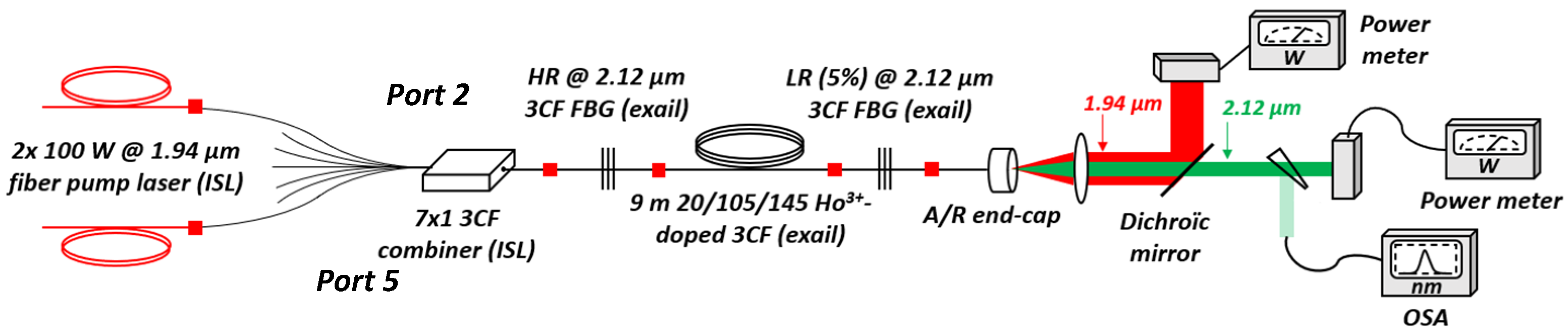
In the work presented in this paper, the main goal of the developed combiner is to demonstrate power scalability from a 2.12 µm triple-clad HDF laser source. By combining the individual CW output powers emitted from several 1.94 µm TDF lasers, the total optical power transmitted by the combiner can be used to resonantly pump at a high level of power the Ho3+ ions doping the core of the active 3CF.
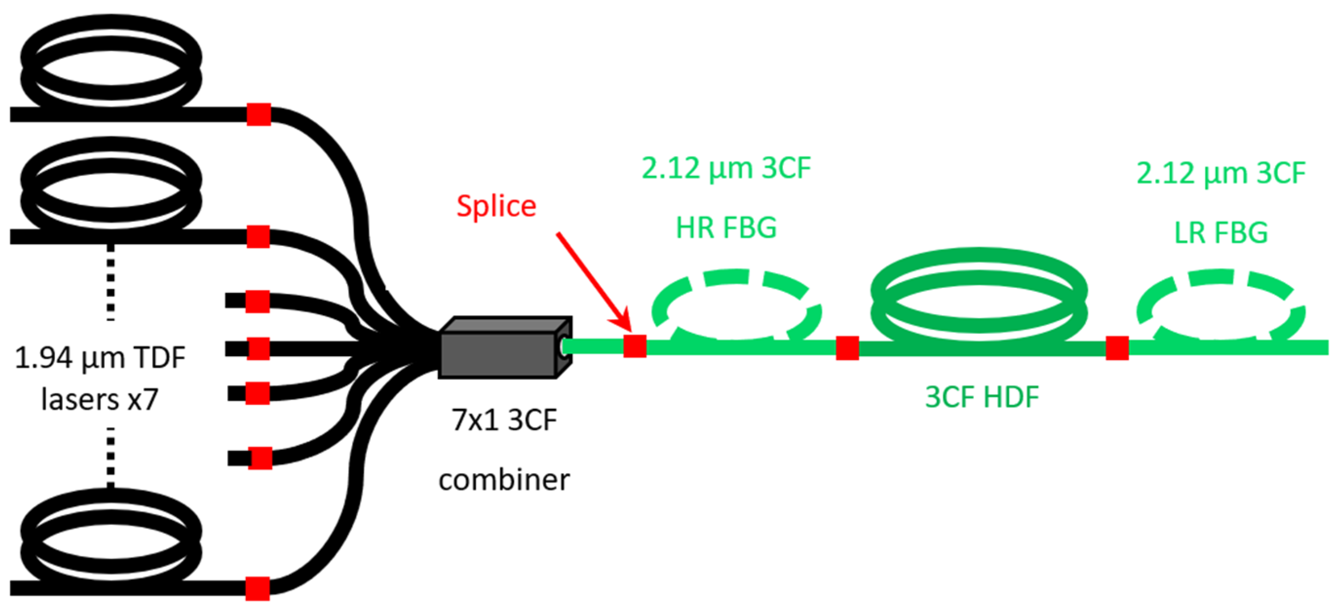
The basic triple-clad HDF laser source architecture investigated and integrating the developed 3CF combiner, is schematically depicted in Figure 1.
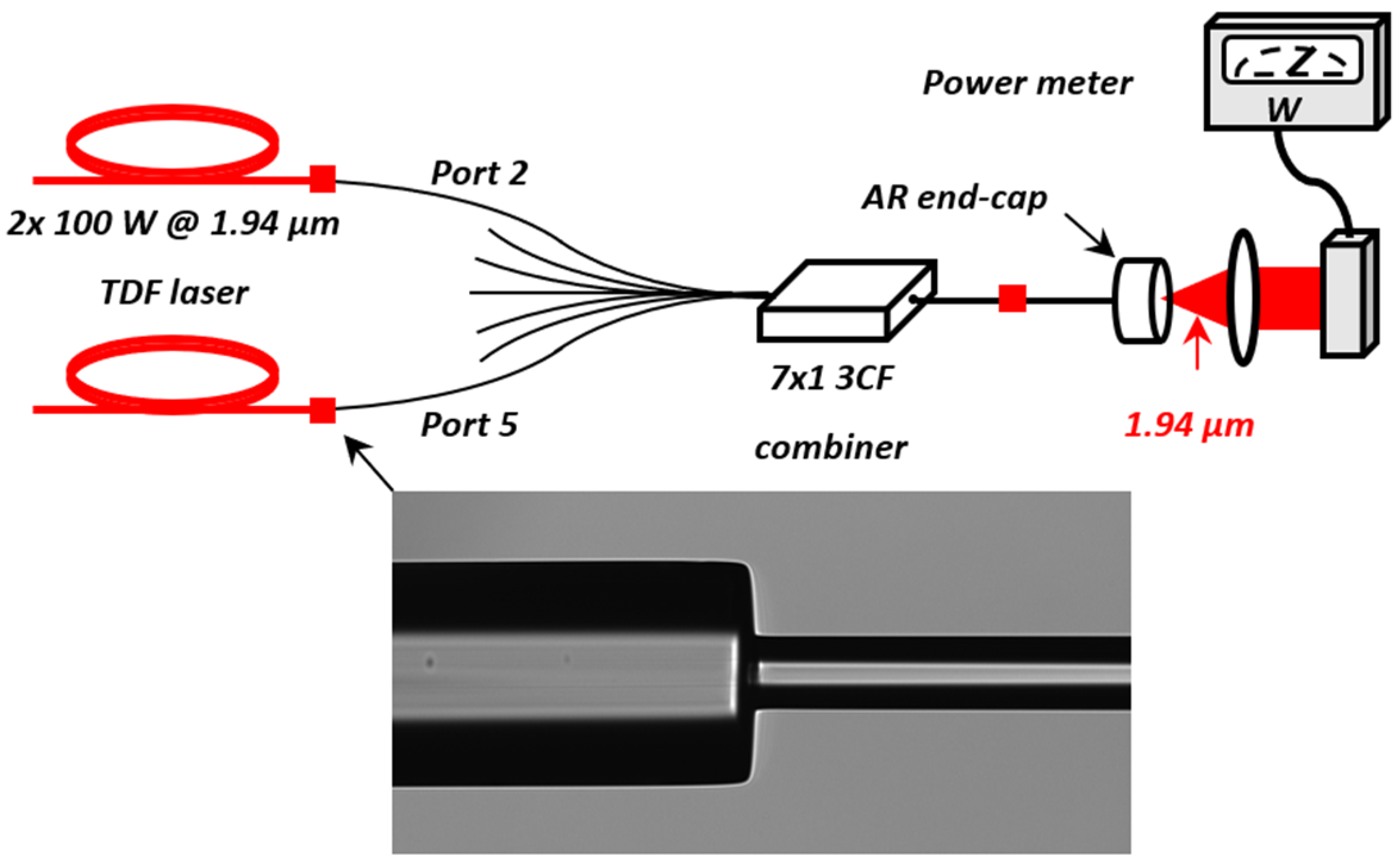
The HDF laser source, schematically represented in Figure 1, is based on an all-fiber typical single-oscillator architecture. It is composed of seven home-made TDF pump lasers emitting at 1.94 µm a CW output power of typically 100 W each. The output fiber of the seven TDF pump sources is single-clad with 20/250 core/cladding diameters (in micrometers) and a core numerical aperture (NA) of 0.08.
The developed 3CF combiner presented in this paper is used to inject the total pump power coming from the seven 1.94 µm TDF lasers into the cladding of the 3CFs (passive and active) positioned, in the laser setup, after the combiner.
The laser cavity is composed of two triple-clad fiber Bragg gratings (FBGs) developed by exail: one high reflectivity (HR) mirror, reflecting > 99% of the intracavity light at 2.12 µm, and one low reflectivity (LR) output coupler, typically reflecting 5–20% of the intracavity radiation at the same wavelength.
The triple-clad HDF, also developed by Exail, has a Ho3+-doped core of 20 µm diameter (NA 0.08) and a doping concentration of 4 × 1025 m−3. A pure silica pump cladding of 105 µm diameter (NA 0.22) is positioned around the core, itself surrounded by a fluorine-doped low refractive-index cladding of 145 µm diameter. Finally, a two-layer acrylate polymer coating of 265 µm diameter is added to protect the fiber from its external environment.
All the fiber components of the laser architecture represented in Figure 1 are fusion-spliced together using different stripping, cleaving, splicing and recoating equipment.

2.2. General Structure of the Developed 7 × 1 3CF Combiner

The developed 3CF pump combiner presented in this paper is aimed to be perfectly adapted to the HDF laser presented in Figure 1. The general structure of the desired 7 × 1 3CF combiner is schematically depicted in Figure 2.
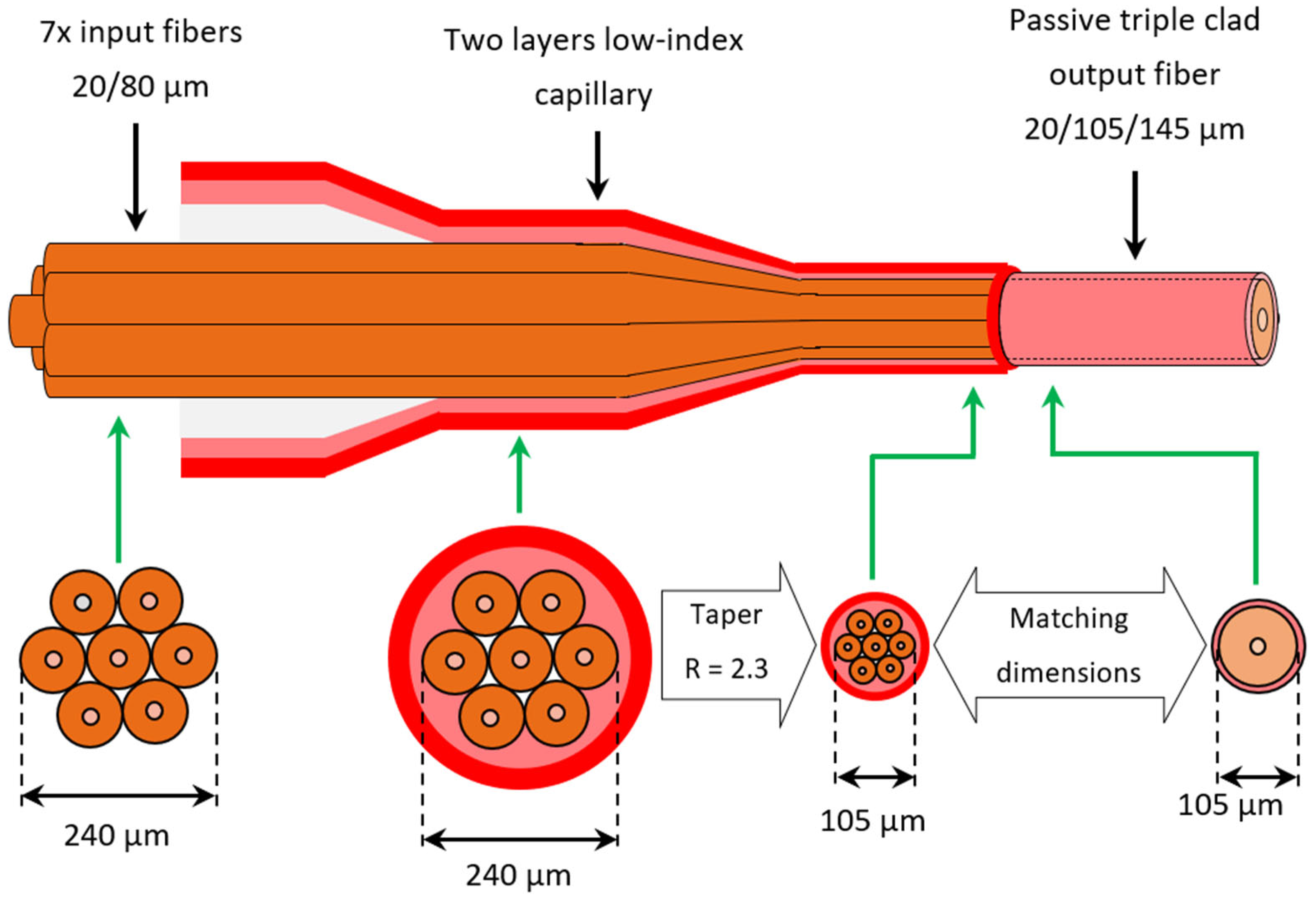
The 3CF combiner, schematically represented in Figure 2, is based on a common end-pumping architecture, for which a bundle of several input fibers is tapered and fusion-spliced to the combiner output fiber. This 3CF combiner is composed of seven single-mode input fibers (SMFs) from Exail, with 20/80/160 core/cladding/coating diameters and a core NA of 0.08. These fibers have the same core dimension/NA as the output fiber core of the seven 1.94 µm TDF laser pump sources of Figure 1 to avoid mode-mismatch losses at the optical splice.
The seven stripped input fibers are inserted in a glass capillary tube, developed by Exail, and composed of two layers of the same thickness: a high refractive index pure silica outer layer and a low refractive index fluorine-doped silica inner one (
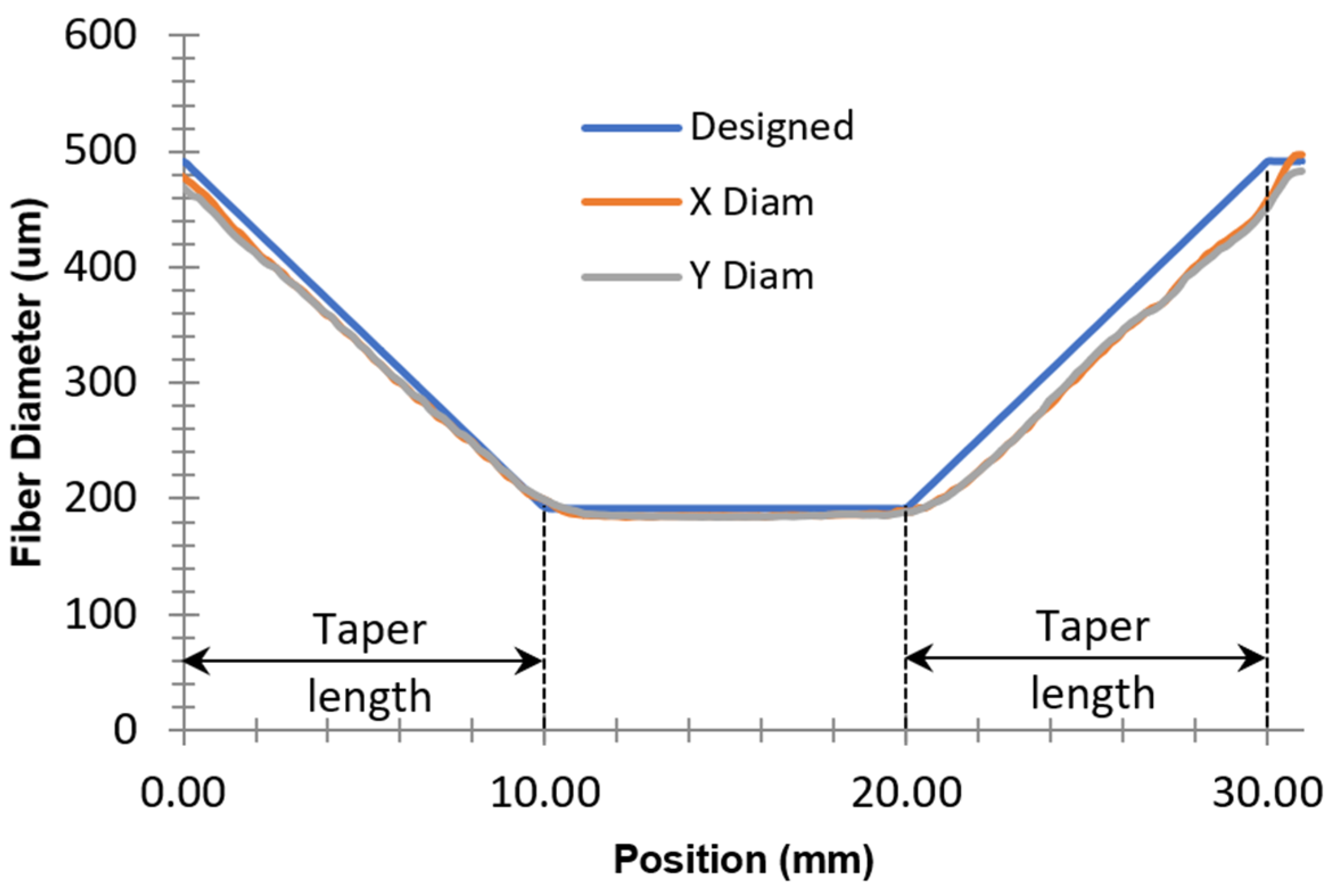
Figure 3). The initial dimensions of the glass capillary tube before the tapering process of the fabrication operations (see Section 3) are 10 cm for the length, 500 µm for the inner hole diameter and 900 µm for the outer pure silica layer diameter.
The inner low refractive index layer of the capillary represented in Figure 3 has been developed in order to have the capability to propagate toward the combiner output fiber any power leaks coming from the seven internal fibers. The power leaks could take their origin from any default occurring in the fabrication operations, or in case of non-adiabatic properties of the tapering process. The optical guiding properties of the capillary tube can help to obtain a low-loss 3CF combiner, thus ensuring, in principle, its compatibility with power scaling. The low refractive index layer thickness has been chosen to have, after tapering, a final thickness > 10λ (with λ = 1.94 µm). This general rule is commonly applied in multimode fibers to prevent any attenuation through the evanescent field of the light propagating in the multimode core [9]. It is also the case in the combiner presented in this study, as any 1.94 µm pump light eventually leaking from the core of the seven internal fibers would propagate in a complex and multimode guiding structure presenting a minimum diameter of 105 µm (after tapering).
The output fiber of the developed combiner presented in Figure 2 is a triple-clad passive fiber manufactured by Exail. This 3CF is a passive version (same dimensions and NA) of the HDF previously presented in Section 2.1 of this section. It has a germanium-doped silica core of 20 µm diameter (NA 0.08), a pure silica pump cladding of 105 µm diameter (NA 0.22) and a fluorine-doped silica outer cladding of 145 µm diameter. The outer cladding of this fiber is coated with a two-layer acrylate polymer of 265 µm final diameter.
As the input fibers present the same cladding dimensions, the capillary cylindrical symmetry naturally confers a hexagonal arrangement to the seven internal stripped fibers (see bottom images of Figure 2). Hence, the maximum size of the internal hexagonal structure is 240 µm before tapering (three times the input fiber cladding diameter of 80 µm). As this structure is placed in front of a multimode guide of 105 µm diameter at the output splice of the combiner, it has to be homothetically reduced by a factor of 240/105 = 2.3. This value will be the targeted taper ratio during the tapering process in the manufacturing operations (see Section 3).
Tapering concern was the motivation for choosing small cladding diameter fibers at the combiner input. Indeed, for a given output fiber and number of input fibers, the bigger the input fibers’ diameter, the higher the tapering ratio. A high tapering ratio of SMFs can lead to a nonadiabatic transition of the light propagating in the tapered section of the fiber. This light leaking from the tapered section is then a source of optical losses and heating for the final combiner. Moreover, a strong homothetical reduction in the diameter of an SMF can induce challenging fabrication conditions to keep symmetry, robustness and easy handling of the tapered fiber. For these reasons, a choice of 80 µm cladding diameter for the combiner input fibers has been made to minimize the tapering ratio and keep the adiabatic properties of the combiner tapered section.

2.3. Adiabatic Tapering Criterion

Adiabatic tapering of an SMF is a gradual and slow homothetical reduction in the fiber dimensions to prevent light from the LP01 fundamental core mode from being coupled to the first LP02 higher order cladding mode [10] (In reference [10], the SMF is single-clad (high refractive index polymer coating). Thus, no light can propagate in the cladding, and only the LP01 mode exists and propagates in the core. Nevertheless, for tapering, a short portion of the fiber is stripped and placed in the air. Consequently, the existence of cladding modes is allowed as the bare fiber is surrounded by a low refractive index medium). In this reference, Stachowiak builds a theoretical model for an axisymmetric linear taper of a single-mode bare fiber placed in the air. A condition on the taper length L to get an adiabatic diameter reduction is then derived and expressed as
L ( R 1 ) 2 π / ( β 1 β 2 ) ,
where R is the taper ratio, and β1 and β2 are the propagation constants of LP01 and LP02 modes of the SMF, respectively.
The adiabatic criterion defined in Equation (1) can be calculated for the combiner presented in this study by numerically determining the propagation constants of the 20/80 SMFs constituting the combiner input ports.
To calculate the propagation constants of the modes of a step-index finite-cladding fiber placed in the air, it is needed to numerically solve the scalar wave equation for the transverse electric field Ψ in the weakly guiding approximation (ncorenclad) defined by [11]:
2 r 2 + 1 r r + 2 Φ 2 + k 2 n 2 β 2 Ψ = 0 .
In Equation (2), r and Φ are the cylindrical coordinates, k = 2π/λ is the wavenumber for the free-space wavelength λ, n is the refractive index profile and β is the propagation constant.
By introducing the effective refractive index neff defined as neff = β/k, the solutions of Equation (2) will depend on each region of the fiber, i.e., the value of neff relative to n. The authors of reference [11] show that the solutions for Ψ in different regions of the fiber can be written as a combination of Bessel functions of the first and second kind Jν and Yν, and modified Bessel functions of the first and second kind Iν and Kν.
Equation (2) can be numerically solved assuming continuity of the transverse electric field Ψ and its derivative d Ψ /d
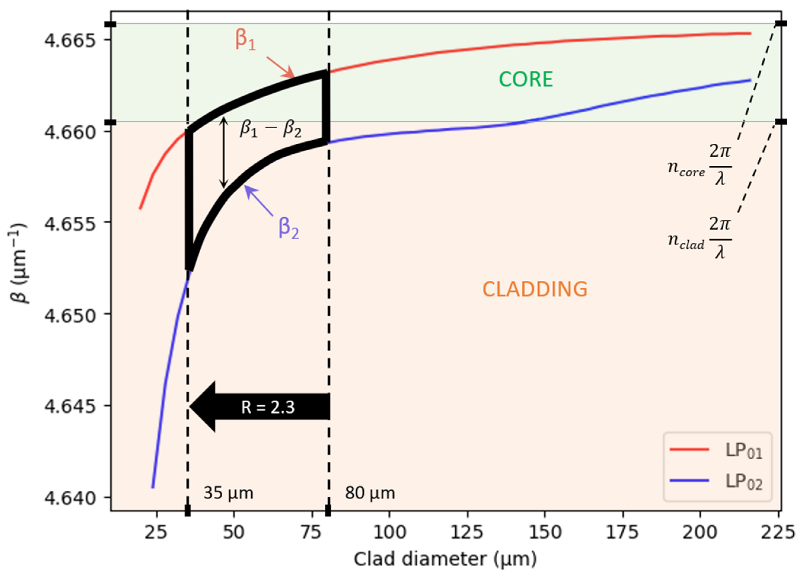
r at the core-cladding and cladding-air interfaces. For the 20/80 SMFs constituting the input ports of the demonstrated 3CF combiner, the evolution of the propagation constants β1 and β2 calculated from our self-written Python (version 3.11) code is plotted in Figure 4.
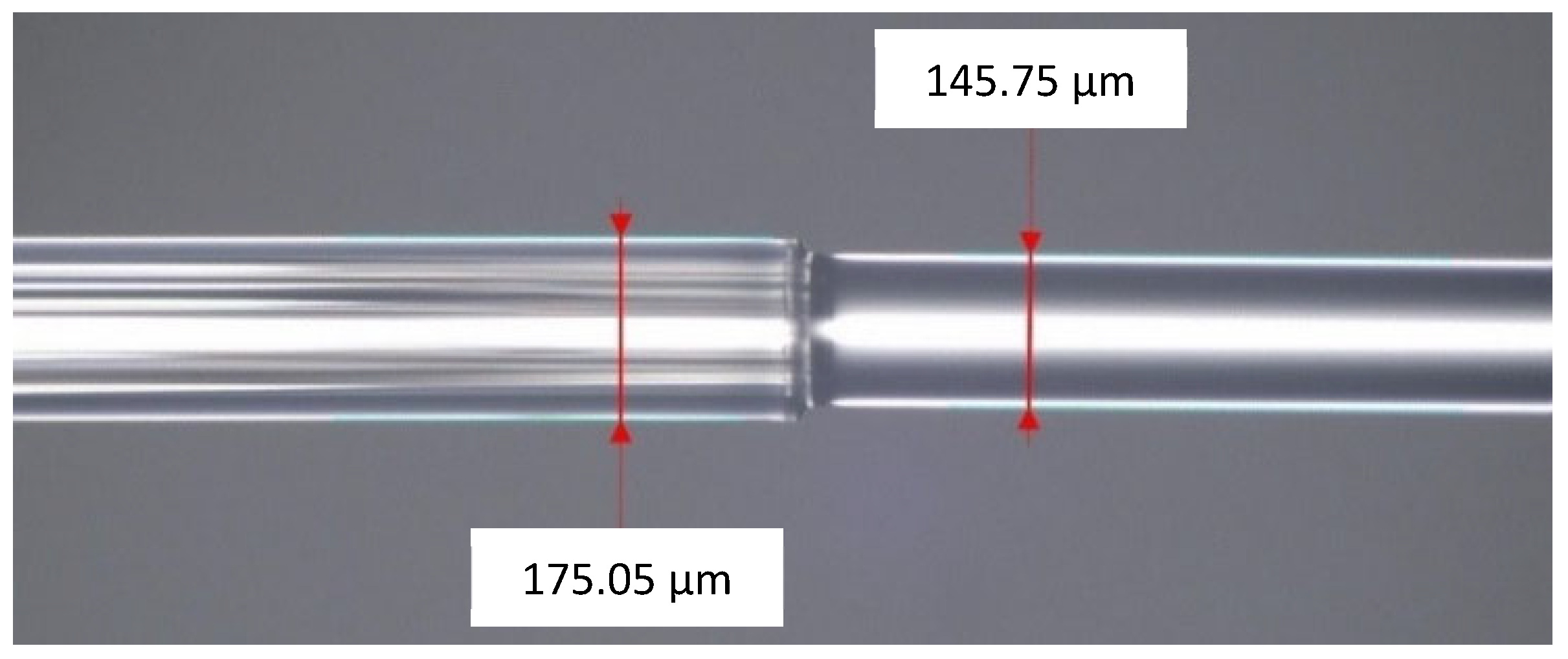
Figure 4 shows that the value of the difference (β1β2), appearing in Equation (1), varies when fiber diameter decreases from 80 µm (original fiber cladding diameter) to 35 µm (final fiber cladding diameter at the end of the taper). Taking the minimum value of (β1β2) represented in Figure 4 gives, from Equation (1), a minimum taper length L for adiabatic tapering of 2.2 mm.
Figure 4 also shows that for an 80 µm cladding diameter, the LP01 mode is propagating in the core region, whereas the LP02 mode is a cladding mode. Nevertheless, when the fiber diameter is reduced along the taper, at the end of the taper, the LP01 mode starts to become a cladding mode (see red curve in Figure 4 near the 35 µm cladding diameter value). This graph indicates that the 1.94 µm pump power originally propagating in the 20/80 SMF core could propagate in the fiber cladding at the end of the taper section of the demonstrated 3CF combiner.
The authors want to emphasize on the limits of validity of the result obtained in Figure 4: Equations (1) and (2) have been derived for a single bare fiber placed in the air [10,11], whereas, in the demonstrated 3CF combiner, each 20/80 fiber is placed in a much more complex environment. Actually, there are seven fibers arranged in a hexagonal structure, and only the six peripheral fibers are surrounded by a two-layer glass capillary tube whose refractive indexes are significantly different from 1. Therefore, the model used to calculate the propagation constants of a single 20/80 SMF cannot quantitatively describe the modes’ properties of this complex structure. Thus, the adiabatic criterion calculated for the minimum taper length L may be incorrect. Nevertheless, the calculation performed in this study indicates some possible trends: first, the 1.94 µm pump power originally propagating in the fiber core (LP01 mode) has, when going through the taper, non-negligible chances to escape from it and propagate in the whole hexagonal structure. This information led to the implementation of a low-index glass capillary in our combiner to direct this pump power to the output fiber, thus limiting optical losses and component heating. Second, the calculated minimum taper length value to get adiabatic properties of a tapered 20/80 SMF (L ≥ 2.2 mm for R = 2.3) can be considered as a first rough approximation. In our fabrication operations, the tapering process will be driven with a taper length L ≫ 2.2 mm.

3. 3CF Combiner Fabrication

The main steps for the fabrication of the combiner schematically represented in Figure 2 can be summarized as following: insertion of the seven input fibers inside the capillary, collapsing of the capillary onto the internal fibers, tapering of the structure, cleaving of the taper and fusion-splicing of the cleaved taper to the combiner output 3CF.

3.1. Input Fibers Insertion in the Two-Layer Capillary

Before the insertion of the 20/80 input fibers, the capillary is pre-tapered with a taper ratio of two, in order to reduce the inner hole diameter to a value of 250 µm. Indeed, directly inserting the seven fibers inside the original hole (500 µm) would result in a deeply asymmetric and random arrangement of the fibers inside the glass tube. Reducing the inner hole diameter by a factor of two induces only 10 µm of tolerance for the bundle of seven fibers being translated through the pre-tapered section (the bundle has a diameter of 240 µm, see Figure 2). This short tolerance on the inner hole diameter helps to obtain almost a perfect hexagonal arrangement of the internal fibers. Perfect symmetry of the arrangement is then completed during the collapsing step of the combiner fabrication. The pre-taperisation of the capillary is performed thanks to a CO2 glass processing platform (Fujikura LZM-100). At the end of the pre-taperisation step, the total length of the capillary is 13 cm. It has a 2 cm long waist of 450 µm outer diameter at the center, and two symmetric tapers of 5 mm length positioned on either side of the waist.
The seven-fiber insertion in the pre-tapered capillary is achieved thanks to commercial capillary loader equipment (3SAE CSL). The extremity of the seven fibers is preliminary stripped over a 10 cm length before insertion. The final glass structure obtained after insertion is then ready for the collapsing step.

3.2. Capillary Collapsing on the Seven Internal Fibers

This fabrication step is aimed at achieving, before tapering, a perfect symmetry of the input fibers’ hexagonal arrangement. Actually, a position shift of any fiber in the hexagonal structure would be preserved during the tapering process. This asymmetric arrangement could lead to difficulties when cleaving the taper (bad cleave surface quality due to inappropriate fracture propagation induced by the cleaver blade). Moreover, any air gap caused by a bad fiber position could result in the formation of bubbles during the final splicing of the taper to the combiner output fiber.
To achieve perfect symmetry of the hexagonal arrangement, a collapse of the capillary pre-tapered section is thermally induced. Heating of the capillary waist is applied until the pressure difference between the capillary internal/external surfaces naturally causes a tube collapse. Thus, the radial force induced by the central downward push of the capillary surface causes the internal fibers to get in contact. At the end of the process, any residual air gap between fibers has vanished, and the seven fibers present a perfect hexagonal symmetry.
Thermally induced collapsing is performed with the CO2 platform. As the heating zone of the platform is approximately 500 µm wide, the 20 mm long waist is heated by longitudinally translating the pre-tapered section through the CO2 laser beam. Different results of capillary collapsing obtained with various heating temperatures (CO2 laser power) are illustrated in Figure 5.
Figure 5a shows that when no heating is applied to the hexagonal structure, the 10 µm tolerance between the bundle of fibers and the pre-tapered inner hole allows fibers to freely move in the tube. This results in poor cleaving quality as previously discussed in this section.
When not enough heating power is applied to the structure (Figure 5b), the capillary starts to collapse and internal fibers adopt an imperfect hexagonal symmetry. Both defects in the fiber positions and residual air gaps also induce relatively bad cleaving results (presence of fractures).
Excessive heating power (Figure 5c) causes the capillary to symmetrically collapse and the structure to completely fuse, resulting in good cleaving results. Nevertheless, the core optical guiding properties of the 20/80 fibers are lost, as we can see from the injected white light that is propagating in the whole structure (no light can be seen in the output fiber cores). We interpret the degradation of the guiding properties of the 20/80 fiber core as a thermally induced diffusion effect of its germanium dopants.
Finally, an appropriate heating power applied to the structure (Figure 5d) shows a well-collapsed capillary with no more air gaps between fibers, leading to good cleaving results. The seven fibers also present a good hexagonal arrangement symmetry. Moreover, the core guiding properties of the 20/80 fibers are preserved, as can be seen from the white light injected in the input central fiber that stays in the fiber core at the capillary output.

3.3. Tapering of the Collapsed Capillary

The goal of the tapering process is to homothetically reduce the dimensions of the structure, composed of seven fibers inserted in the low-index capillary (Figure 5d), to the dimensions of the combiner output 3CF. As discussed in Section 2.2, the targeted tapering ratio is R = 2.3, with a taper length L ≫ 2.2 mm for adiabaticity concern (see Section 2.3). In these conditions, the outer diameter of the capillary collapsed section (including internal fibers) will be decreased from approximately 440 µm to 191 µm at the taper end. In this situation, the final diameter of the inner tapered hexagonal arrangement of fibers is 105 µm, as wanted in the combiner design (see Figure 2).
The tapering is performed with the Fujikura LZM-100 CO2 laser platform. During the process, the capillary is clamped on both extremities in the left and right translation stages of the LZM-100 platform. The 20 mm long collapsed section of the capillary is then longitudinally translated in the left direction through the CO2 laser beam. To induce a diameter reduction, the translation speed of the left stage varies during heating, whereas the right stage is maintained at a constant speed. As the capillary diameter is modified during the tapering process, the laser power is adjusted in real time to control the heat brought to the capillary (absorption of the CO2 laser beam by the glass material depends on its diameter).
Once the tapering process is accomplished, the diameter evolution along the tapered structure can be measured by the LZM-100 platform. Figure 6 shows a typical diameter profile obtained from this measurement.
After tapering, Figure 6 shows that the capillary collapsed section has been elongated from 20 mm (original length) to 30 mm. A 10 mm long waist with 195 µm diameter is positioned at the center of the structure. This waist length has been chosen to facilitate the upcoming cleaving operation. The waist is surrounded on both sides by two symmetric linear tapers of 10 mm length. Both tapers correspond to the acceleration and deceleration phases of the LZM left translation stage. A taper length L of 10 mm has been chosen to fulfil the adiabatic criterion L ≫ 2.2 mm defined in Section 2.3.

3.4. Fusion-Splicing of the Final Taper to the Output 3CF

To fusion-splice the taper to the combiner output 3CF, the tapered structure presented in Section 3.3 of this section is cleaved at the waist center. The cleaving operation is performed with a Fujikura CT-106 large diameter cleaver.
A fusion-splice between cleaved taper and 3CF (also previously cleaved with CT-106 cleaver) is then operated with the LZM-100 platform. A typical example of the resulting splice is illustrated in Figure 7.
Figure 7 shows a slight difference between the taper diameter (175 µm) and the 3CF diameter (145 µm). This difference is intentional and due to the presence of the additional pure silica outer layer of the capillary (see Figure 3). But internally, the hexagonal arrangement diameter matches the 3CF pump cladding diameter (105 µm).
In the splicing result example given in Figure 7, the 175 µm outer diameter of the taper end is slightly different from the 195 µm value presented in Figure 6. This is due to fluctuating dimensions from one capillary to another during fabrication.
At the end of the fusion-splicing process, 3CF combiner fabrication is completed. For optical characterization presented in Section 4, the bare fiber component has been integrated into a mechanical packaging. This packaging has two functions: safely handling the combiner to avoid any damage, and being able to cool down any potential heating of the combiner when used at high optical powers. The development of mechanical packaging is not presented here as it is out of the scope of this paper.

4. 3CF Combiner Optical Performances

To evaluate the optical transmission and power handling of the developed 3CF combiner, two high-power TDF laser sources, developed at ISL and each delivering 100 W at 1.94 µm [12], have been connected to the combiner input fibers, as schematically represented in Figure 8.
The two input fibers (ports 2 and 5) of Figure 8 fusion-spliced to the TDF pump sources are peripheral fibers in the hexagonal arrangement of Figure 5d. As discussed in Section 2.1, the output fiber of the two TDF lasers is a 20/250 (NA 0.08) single-clad fiber. Fusion-splicing of these fibers to the 20/80 (NA 0.08) combiner input fibers has been performed with a Vytran GPX-3000 glass processing system and a Fujikura CT-106 cleaver. An image of the resulting splice extracted from the GPX splicer is illustrated in Figure 8.
The 20/80 combiner input fibers present non-negligible micro-bending losses due to their high core/cladding ratio [13]. They have been carefully measured with a cut-back method to be 0.4 dB/m. The 20/80 fiber length is 120 cm in the setup shown in Figure 8, bringing the power losses introduced by the input fibers to 11%.
The combiner output 3CF is fusion-spliced to a 1.94 µm anti-reflection (AR) coated 3CF end-cap from Fiberbridge Photonics, to prevent the combiner from any back-reflected light that could damage it. The end-cap input 3CF is the same as the one integrated at the combiner output. Fusion-splice between combiner and end-cap has been performed with a CT-106 cleaver and a Fujikura FSM-100P + splicer. To measure the end-cap output power, a 1.94 µm AR-coated collimating lens (focal length 50 mm) and a Thorlabs PM100D power meter with a S322C power head were used.
The end-cap output power evolution with the total 1.94 µm power emitted from the TDF lasers outputs is depicted in Figure 9.
Figure 9 shows that the maximum available 1.94 µm power has been injected into the 3CF combiner without damaging it. The total optical losses of the setup represented in Figure 8 are 16%. As described above, since the micro-bending losses in the 20/80 input fibers account for 11% of the total losses, the internal structure of the combiner (taper + inner splice) has an optical transmission > 95% (as input splicing losses varies from 2% to 4% from one splice to another (imperfect reproducibility of the splices due to cleave angle variations), combiner transmission is given splice losses included to avoid any transmission uncertainties.) for input pump ports 2 and 5, which is typically comparable to high-quality commercial fiber pump combiners. Shortening the 20/80 input fibers’ length may help to reduce the global optical losses of the combiner (input fibers included). A reasonably useful length of 30 cm would increase global optical transmission of this combiner to a value > 92% at high power, which is still an acceptable performance for such a specific high-power 1.94 µm 3CF pump combiner. The optical transmission of other pump ports has been measured at low power using a fiber-coupled single-mode laser diode (Thorlabs FPL1940S, pigtail fiber SM1950) delivering a few milliwatts at 1.94 µm, and successively spliced to each input pump port. Table 1 resumes the obtained values. Calculated transmissions are splice losses included and micro-bending losses excluded.
Intermediate measurements during combiner fabrication have been performed at the cleaved taper output. No significant optical losses could be measured at this section of the combiner, meaning that the combiner losses are mainly located at the internal splice to the output 3CF.
Temperature measurement of the uncooled combiner housing at the maximum 1.94 µm power has shown no significant heating of the component, confirming the low-loss property of its internal structure.
The transmission of the input fiber positioned at the center of the hexagonal arrangement has been measured at 1.94 µm to be higher than 97% when not taking into account the fiber micro-bending extra losses. Contrary to the other input fibers, the core of this one is spliced directly to the 3CF core. Thus, part of the incoming power will be injected and propagate into the output fiber core. Actually, 40% of the incoming power has been measured to propagate in the 3CF core, whereas 60% is in its cladding. This repartition of the power should be taken into account when designing the final laser system. Finally, we note that the 7 × 1 3CF combiner can also be used as a beam combiner for MOPA systems in a 6 + 1 × 1 configuration if the core/cladding power repartition fits with experimental setup requirements.

5. Integration of the 3CF Combiner into a Ho3+-Doped Fiber Laser

Following the schematic of the laser architecture represented in Figure 1, the demonstrated 3CF combiner has been integrated into the HDF laser. The experimental setup built for this demonstration is represented in Figure 10.
Figure 10 shows that the HDF laser setup is based on a single-oscillator architecture. The two TDF laser pump sources are the same as the ones represented in Figure 8, delivering each 100 W at 1.94 µm. The single-mode output fibers of the pump lasers are spliced to input ports 2 and 5 of the 3CF combiner. The laser cavity is based on two 2.12 µm FBGs, one with HR and one with 5% of reflectivity used as an output coupler. The HDF of 9 m is a triple-clad fiber with a core of 20 µm diameter (NA 0.08) and a doping concentration of 4 × 1025 m−3. A pure silica pump cladding of 105 µm diameter (NA 0.22) is positioned around the core, itself surrounded by a fluorine-doped low refractive-index cladding of 145 µm diameter. An Anti-Reflection (AR) coated fused-quartz endcap is spliced at the laser output to prevent any light feedback in the 3CF combiner at pump and laser wavelengths. Pump and laser output beams are collimated using a 50 mm AR-coated lens. A dichroïc mirror is used to separate the pump and laser output beams. Two power meters (Thorlabs PM100D + S322C head) are used to measure pump and laser output powers. Finally, a small portion of the laser output power is taken using an uncoated prism to measure the laser output power spectrum with an Optical Spectrum Analyzer (Yokogawa AQ6376E).
The output powers obtained from the laser setup, schematically represented in Figure 10, are depicted in Figure 11.
Figure 11 shows that a 2.12 µm laser maximum output power of 101 W has been achieved for a 1.94 µm injected pump power of 170 W (pump-power-limited setup). The laser setup exhibits an unabsorbed residual output pump power of 23 W at maximum power for an optimized HDF length of 9 m (longer HDF length leads to lower efficiencies). The laser slope efficiency achieved is 61%. Taking into account the absorbed pump power, the laser slope efficiency is increased to 72%. These values are, to the best of our knowledge, the highest demonstrated laser efficiencies for a 1.9 µm cladding-pumped HDF laser source.
The laser output power spectrum emitted by the experimental setup represented in Figure 10 is depicted in Figure 12.
Figure 12 shows a spectral power density centered at 2118.9 nm, corresponding to the central wavelength of the FBGs, and a linewidth of 0.5 nm. The spectrum is stable and no spectral broadening has been observed with the increasing pump power (insert of Figure 12), indicating no nonlinear effect occurring within the power range available in this experimental study.

6. Discussion

The 3CF combiner demonstrated in this study has shown a high-power transmission of its internal structure at 1.94 µm, higher than 95% (splice losses included) when not taking into account micro-bending losses of the 20/80 combiner input fibers, making this component compatible with further power-scaling (>200 W input power). This high-power compatibility is also confirmed by the thermal behavior of the combiner, showing no significant temperature rise of its packaging at maximum power. These characteristics of the component are achieved thanks to the implementation in the combiner structure of an optically guiding capillary, propagating toward the output fiber cladding any potential power leaks coming from the tapered structure. Hence, the low refractive index capillary appears here as a structural advantage of the proposed combiner design.
Another advantage of the combiner design concerns the choice of its input fibers. Indeed, the 20/80 input fibers are single-mode, enabling the combiner to be used either in a 7 × 1 or 6 + 1 × 1 configuration. This characteristic of the combiner leads to the possibility of using it either in single oscillator or MOPA architectures for the HDF laser, which is remarkable.
Nevertheless, the 20/80 single-mode input fibers also bring some additional optical losses (micro-bending) due to their high core/cladding ratio, which is unoptimized in terms of wall-plug efficiency of the laser system and maximum handling power of each input port. This problem can be addressed by shortening the input fiber length to reduce losses, or by choosing higher cladding diameters if it is compatible with internal taper adiabaticity.
Another point concerns the 40% of power propagating in the cladding when injecting light in the input central fiber core (see Section 4). In the case of a MOPA architecture, this proportion of 2.1 µm laser power propagating in the HDF cladding may lead to laser beam degradation (multimode components present in the transverse output beam) at the laser output. A complete study of HDF lasers’ characteristics, presenting single oscillator and MOPA architectures, and integrating the demonstrated 3CF combiner, will be published later in another paper.

7. Conclusions

In this paper, we present, for the first time, to our knowledge, the development and study of a 1.94 µm fiber pump combiner based on a triple-clad output fiber. The developed 7 × 1 3CF combiner is based on an end-pumping architecture and presents high optical transmission thanks to a low refractive index glass capillary implemented in the combiner. The component was able to handle up to 200 W of continuous wave power at 1.94 µm, with no significant heating measured on the combiner housing. Due to its low loss and low heating properties, the developed combiner is compatible with the power scaling of holmium-doped fiber lasers cladding-pumped around 1.9 µm. Thanks to seven single-mode input fibers disposed in a hexagonal arrangement, the combiner can also be used in a 6 + 1 × 1 configuration, making this component compatible with holmium-doped fiber lasers based on both single-oscillator and MOPA architectures. First results with an HDF laser source integrating the demonstrated 3CF combiner in a single oscillator architecture have shown its ability to be used in a laser system. The laser slope efficiency achieves 61%, which is, to the best of our knowledge, the highest demonstrated laser efficiency for a 1.9 µm cladding-pumped HDF laser source.

Author Contributions

Conceptualization, N.D., S.B., A.H.-D. and T.R.; methodology, N.D.; software, S.B.; validation, N.D.; formal analysis, N.D. and S.B.; investigation, N.D.; resources, N.D., T.I. and T.R.; data curation, N.D.; writing—original draft preparation, N.D.; writing—review and editing, N.D., T.I., S.B., C.L. and A.H.-D.; visualization, N.D.; supervision, A.H.-D.; project administration, N.D.; funding acquisition, N.D. and A.H.-D. All authors have read and agreed to the published version of the manuscript.

Funding

This work was supported by the French Direction Générale de l’Armement (DGA) and the French Agence de l’innovation de défense (AID) under grant number 202906077.

Institutional Review Board Statement

Not applicable.

Informed Consent Statement

Not applicable.

Data Availability Statement

Data underlying the results presented in this paper are not publicly available at this time but may be obtained from the authors upon reasonable request.

Conflicts of Interest

Thierry Robin was employed by the company Exail. The remaining authors declare that the research was conducted in the absence of any commercial or financial relationships that could be construed as a potential conflict of interest.

References

  1. Titterton, D.H. Military Laser Technology and Systems, 1st ed.; Artech House: London, UK, 2015. [Google Scholar]
  2. Holmen, L.G.; Shardlow, P.C.; Barua, P.; Sahu, J.K.; Simakov, N.; Hemming, A.; Clarkson, W.A. Tunable holmium-doped fiber laser with multiwatt operation from 2025 nm to 2200 nm. Opt. Lett. 2019, 44, 4131–4134. [Google Scholar] [CrossRef] [PubMed]
  3. Baer, P.; Cebeci, P.; Reiter, M.; Giesberts, M.; Hoffmann, H.-D. 10 W-class, narrow-linewidth, linearly polarized, low-noise holmium-doped fiber amplifier at 2095 nm. Opt. Contin. 2024, 3, 1302–1310. [Google Scholar] [CrossRef]
  4. Simakov, N.; Hemming, A.; Clarkson, W.A.; Haub, J.; Carter, A. A cladding-pumped, tunable holmium doped fiber laser. Opt. Express. 2013, 21, 28415–28422. [Google Scholar] [CrossRef] [PubMed]
  5. Hemming, A.; Bennetts, S.; Simakov, N.; Davidson, A.; Haub, J.; Carter, A. High power operation of cladding pumped holmium-doped silica fibre lasers. Opt. Express 2013, 21, 4560–4566. [Google Scholar] [CrossRef] [PubMed]
  6. Beaumont, B.; Bourdon, P.; Barnini, A.; Kervella, L.; Robin, T.; Le Gouët, J. High efficiency holmium-doped triple-clad fiber laser at 2120 nm. J. Light. Technol. 2022, 40, 6480–6485. [Google Scholar] [CrossRef]
  7. Le Gouët, J.; Gustave, F.; Bourdon, P.; Robin, T.; Laurent, A.; Cadier, B. Realization and simulation of high-power holmium doped fiber lasers for long-range transmission. Opt. Express 2020, 28, 22307–22320. [Google Scholar] [CrossRef] [PubMed]
  8. Hemming, A.; Simakov, N.; Davidson, A.; Bennetts, S.; Hughes, M.; Carmody, N.; Davies, P.; Corena, L.; Stepanov, D.; Haub, J.; et al. A monolithic cladding pumped holmium-doped fiber laser. In Proceedings of the CLEO: Science and Innovations, San Jose, CA, USA, 9–14 June 2013. [Google Scholar]
  9. Skutnik, B.J.; Park, H. Cladding effects on spectral transmission of optical fibers for medical applications. In Proceedings of the SPIE, San Jose, CA, USA, 22–23 January 2002. [Google Scholar]
  10. Stachowiak, D. High-Power Passive Fiber Components for All-Fiber Lasers and Amplifiers Application—Design and Fabrication. Photonics 2018, 5, 38. [Google Scholar] [CrossRef]
  11. Love, J.D.; Henry, W.M.; Stewart, W.J.; Black, R.J.; Lacroix, S.; Gonthier, F. Tapered single-mode fibres and devices, Part 1: Adiabaticity criteria. Proc. Inst. Electr. Eng. 1991, 138, 343–354. [Google Scholar] [CrossRef]
  12. Louot, C.; Sanson, F.; Motard, A.; Ibach, T.; Manek-Hönninger, I.; Berrou, A.; Dalloz, N.; Robin, T.; Cadier, B.; Hildenbrand-Dhollande, A. Emission Wavelength Limits of a Continuous-Wave Thulium-Doped Fiber Laser Source Operating at 1.94 µm, 2.09 µm or 2.12 µm. Photonics. 2024, 11, 216. [Google Scholar] [CrossRef]
  13. Marcuse, D. Microdeformation losses of single-mode fibers. Appl. Opt. 1984, 23, 1082–1091. [Google Scholar] [CrossRef] [PubMed]
Figure 1. Schematic of the typical triple-clad HDF laser source investigated. The green color in the schematic represents 3CFs.
Photonics 12 00659 g001
Figure 2. Schematic of the 7 × 1 3CF combiner developed and presented in this study. Bottom images represent different cross-sections along the combiner structure.
Photonics 12 00659 g002
Figure 3. End-face microscope image (Keyence VHX-970F) of the two-layer glass capillary tube developed by Exail. The 100 µm-thick inner layer is composed of fluorine-doped low refractive index silica glass. The 100 µm-thick outer layer is made of undoped pure silica high refractive index glass.
Photonics 12 00659 g003
Figure 4. Evolution of the propagation constant β of the LP01 (in red) and LP02 (in blue) modes of the 20/80 step-index bare fiber placed in the air. The vertical black double arrow between red and blue curves shows the evolution of the (β1β2) difference along the taper length L and for a tapering ratio R of 2.3.
Photonics 12 00659 g004
Figure 5. End-face microscope images (Keyence VHX-970F) of the collapsed capillary for different heating powers. (a) No heating. (b) Low heating. (c) Strong heating. (d) Appropriate heating. For (bd) images, white light is injected in the core of the input 20/80 fibers.
Photonics 12 00659 g005
Figure 6. Diameter evolution along the tapered collapsed section of the capillary measured with the Fujikura LZM-100 platform. X and Y diameters correspond to the diameters measured by both internal cameras, providing two different viewing angles separated by 90°.
Photonics 12 00659 g006
Figure 7. Microscope image (Keyence VHX-970F) of the fusion-splice performed with the CO2 platform between cleaved taper (left) and output 3CF (right).
Photonics 12 00659 g007
Figure 8. Schematic of the experimental setup built to evaluate the optical performances of the developed 3CF combiner.
Photonics 12 00659 g008
Figure 9. Output power evolution of the experimental setup of Figure 8 versus total 1.94 µm power emitted from the TDF lasers.
Photonics 12 00659 g009
Figure 10. HDF laser single oscillator experimental setup integrating the demonstrated 3CF combiner.
Photonics 12 00659 g010
Figure 11. Laser and residual unabsorbed pump powers evolution with injected 1.94 µm pump power for the HDF laser setup represented in Figure 10.
Photonics 12 00659 g011
Figure 12. Normalized spectral power density of the output beam emitted at maximum pump power by the laser setup depicted in Figure 10. Insert: evolution of the spectrum with the pump power on log scale.
Photonics 12 00659 g012
Table 1. 3CF combiner optical transmission of other input pump ports measured using a fiber-coupled single-mode laser diode (Thorlabs FPL1940S, pigtail fiber SM1950) delivering 15 mW at 1.94 µm.
InputOptical Transmission (Splice Losses Included)
Port 1 (central fiber)>97%
Port 3>94%
Port 4>93%
Port 6>95%
Port 7>95%
Disclaimer/Publisher’s Note: The statements, opinions and data contained in all publications are solely those of the individual author(s) and contributor(s) and not of MDPI and/or the editor(s). MDPI and/or the editor(s) disclaim responsibility for any injury to people or property resulting from any ideas, methods, instructions or products referred to in the content.

