Article

A Study of Ultra-Thin Surface-Mounted MEMS Fibre-Optic Fabry–Pérot Pressure Sensors for the In Situ Monitoring of Hydrodynamic Pressure on the Hull of Large Amphibious Aircraft

1
AVIC General Huanan Aircraft Industry Co., Ltd., Zhuhai 519040, China
2
National Laboratory of Solid State Microstructures, College of Engineering and Applied Sciences, Nanjing University, Nanjing 210093, China
3
MIIT Key Laboratory of Aerospace Information Materials and Physics, State Key Laboratory of Mechanics and Control for Aerospace Structures, College of Physics, Nanjing University of Aeronautics and Astronautics, Nanjing 211106, China
4
Aviation Key Laboratory of Science and Technology on High-Speed Hydrodynamic, China Special Vehicle Research Institute, Jingmen 448035, China
*
Authors to whom correspondence should be addressed.
These authors contributed equally to this work.
Photonics 2025, 12(7), 627; https://doi.org/10.3390/photonics12070627
Submission received: 18 May 2025 / Revised: 10 June 2025 / Accepted: 18 June 2025 / Published: 20 June 2025

Abstract

:
Hydrodynamic slamming loads during water landing are one of the main concerns for the structural design and wave resistance performance of large amphibious aircraft. However, current existing sensors are not used for full-scale hydrodynamic load flight tests on complex models due to their large size, fragility, intrusiveness, limited range, frequency response limitations, accuracy issues, and low sampling frequency. Fibre-optic sensors’ small size, immunity to electromagnetic interference, and reduced susceptibility to environmental disturbances have led to their progressive development in maritime and aeronautic fields. This research proposes a novel hydrodynamic profile encapsulation method using ultra-thin surface-mounted micro-electromechanical system (MEMS) fibre-optic Fabry–Pérot pressure sensors (total thickness of 1 mm). The proposed sensor exhibits an exceptional linear response and low-temperature sensitivity in hydrostatic calibration tests and shows superior response and detection accuracy in water-entry tests of wedge-shaped bodies. This work exhibits significant potential for the in situ monitoring of hydrodynamic loads during water landing, contributing to the research of large amphibious aircraft. Furthermore, this research demonstrates, for the first time, the proposed surface-mounted pressure sensor in conjunction with a high-speed acquisition system for the in situ monitoring of hydrodynamic pressure on the hull of a large amphibious prototype. Following flight tests, the sensors remained intact throughout multiple high-speed hydrodynamic taxiing events and 12 full water landings, successfully acquiring the complete dataset. The flight test results show that this proposed pressure sensor exhibits superior robustness in extreme environments compared to traditional invasive electrical sensors and can be used for full-scale hydrodynamic load flight tests.

1. Introduction

The in situ monitoring of hydrodynamic loads during water landing on large amphibious aircraft represents a critical technological challenge in fluid–structure interaction (FSI) dynamics analysis and airworthiness certification [1]. Hydrodynamic loads, generated by transient hull–water slamming/impacts during take-off/landing, exhibit high-frequency spatiotemporal distributions that directly govern structural fatigue life prediction accuracy and wave resistance optimization strategies [2,3]. Theoretical studies confirm that aircraft water-entry processes demonstrate strongly nonlinear FSI characteristics, with dynamic behaviours analogous to wedge-shaped-body water impact effects [4,5]. The structural vibration mode distortion [3,6] and local plastic damage risks [7,8,9,10] caused by such transient events urgently necessitate the development of high-fidelity in situ sensing technology to support the safety design of hulls [11,12].
Current hydrodynamic load research methods encompass analytical [13,14,15] or semi-analytical tests [16,17,18,19,20,21,22,23,24,25], numerical simulations [2,26,27,28,29,30,31,32,33,34] (e.g., coupled SPH-VOF algorithms [35]), and scaled model tests [9,36]. While computational fluid dynamics (CFD) can simulate three-phase flow fields during amphibious aircraft water entry [37,38,39], its predictive accuracy remains constrained by turbulence model closure issues [7] and experimental validation gaps in dynamic mesh algorithms [40]. Although scaled tests acquire pressure–time history curves [41], Froude number (Fr) and Reynolds number (Re) scaling effects hinder the accurate reconstruction of full-scale load spectrum characteristics [42]. Hydrodynamic aircraft load measurements must satisfy extreme operational constraints [43]: wide range (−100 kPa to 2 MPa), high sampling frequency (10 kHz), multi-channel microsecond-level synchronous acquisition accuracy (≤0.5% F.S.), and resistance to seawater corrosion.
Traditional invasive electrical sensors (e.g., piezoresistive/piezoelectric types) are widely used in marine and aerospace applications for scaled model tests [44,45,46,47,48,49,50], but their structural damage risks fundamentally conflict with airworthiness requirements for flight tests [51]. Specific limitations include the following: (1) structural integrity degradation: Sensor installation requires 5 mm diameter holes, causing 8–10% global stiffness reduction and 20% fatigue life reduction if over 250 points need to be measured (exceeding ≤5% airworthiness tolerance), violating the “no permanent structural damage” principle in CCAR-25-R4 [52]. (2) Flow field disturbance: Holes induce boundary-layer separation, increasing local vortex intensity by 30% and causing ±12% pressure measurement deviation [53]. (3) Insufficient environmental adaptability: Statistics from the China Flight Test Establishment reveal a <50% survival rate for invasive sensors in salt fog environments due to diaphragm rupture and short circuits after water landing [54].
Non-invasive technologies such as pressure-sensitive paint (PSP) [47] and fibre Bragg grating (FBG) sensors [10,55] circumvent structural damage but face technical bottlenecks: PSP suffers from limited spatial resolution (<5 mm) and oxygen-concentration-dependent errors (>8%). Fibre-optic sensing technology has garnered significant attention due to its immunity to electromagnetic interference and distributed measurement capabilities [56,57,58,59,60,61]. Representative examples include Waskito et al. [62], who reconstructed hull wave pressure fields using 333 FBG pressure sensors on a scaled bulk carrier model, and Xu et al. [63], who developed a temperature self-compensated FBG pressure sensor with a sensitivity of 58.94 pm/kPa. However, existing surface-mounted FBG pressure sensors remain inadequate for large amphibious aircraft testing requirements in terms of range (<500 kPa), packaging thickness (>3 mm), high-frequency synchronous acquisition (<5 kHz), and high-temperature sensitivity.
Notably, while conventional microelectromechanical system (MEMS) fibre-optic Fabry–Pérot (FP) pressure sensors exhibit excellent high-frequency responses (natural frequency ≥ 2 MHz) and a wide measurement range (−100 kPa to 10 MPa) [64,65], their rigid surface-mounted packaging structures (thickness ≥ 5 mm) significantly increase hull surface flow resistance, severely limiting engineering applicability. Therefore, currently, there is no non-invasive pressure sensor and acquisition system that can meet the above demands for the in situ monitoring of hydrodynamic loads on the hull of large amphibious aircraft.
To address these technical contradictions, this paper proposes a novel hydrodynamic profile encapsulation method using an ultra-thin surface-mounted MEMS fibre-optic FP pressure sensor (total thickness 1 mm). Then, hydrostatic calibration tests for pressure and temperature were conducted. The test results show that this ultra-thin surface-mounted MEMS fibre-optic FP pressure sensor has an exceptional linear response and low-temperature sensitivity. In addition, the proposed pressure sensor was tested simultaneously with electrical sensors in water-entry tests of a wedge-shaped body and showed superior response and detection accuracy. This work exhibits significant potential for the in situ monitoring of hydrodynamic loads, contributing to the research of large amphibious aircraft. Furthermore, this research is the first in the world to successfully use the proposed surface-mounted sensors for flight tests of water landings on a large amphibious prototype. The flight test results show that this ultra-thin surface-mounted MEMS fibre-optic FP pressure sensor exhibits superior robustness in extreme environments compared to traditional invasive electrical sensors.

2. The Principle of MEMS Fibre-Optic Fabry–Pérot Pressure Sensors

Figure 1 presents a schematic cross-sectional model of a typical MEMS fibre-optic FP pressure sensor. Based on the principle of Fabry–Pérot interferometry, this sensing device converts external pressure fluctuations into cavity length modulation within the FP interferometric cavity via a pressure-sensitive diaphragm. The inner surface of the pressure-sensitive diaphragm (R1) and the optical fibre end face (R2) collectively form the two reflective interfaces of the Fabry–Pérot cavity.
The resulting reflected spectral intensity distribution, IR(λ), can be described by the following mathematical expression [64]:
I R ( λ ) = I 1 + I 2 + 2 I 1 I 2 cos ( Δ φ + φ 0 )
Δ φ = 4 π n L λ
where I1 and I2 denote the light intensity responses at reflective interfaces R1 and R2, respectively; n represents the refractive index of the cavity medium; L denotes the geometric cavity length; φ0 is the initial optical phase parameter; Δφ represents the phase difference between the two coherent reflected beams.
According to the thin-plate elastic deformation theory, the application of external pressure to the pressure-sensitive diaphragm induces elastic deflection. This deformation modifies the effective cavity length of the Fabry–Pérot cavity, thereby altering the characteristic interference spectrum formed at reflective surfaces R1 and R2. The mathematical representation of this physical process is given by the following [64]:
Δ L = 3 ( 1 ν 2 ) R 4 16 E d 3 Δ p
where ν and E denote the Poisson’s ratio and Young’s modulus of the diaphragm material, respectively; R represents the diaphragm radius; d is the diaphragm thickness; ∆p corresponds to the change in ambient pressure.
Based on the above principle of the sensing mechanism, the design and fabrication process of the Fabry–Pérot cavity in fibre-optic pressure sensors constitute a critical determinant of pressure sensitivity. The pressure sensitivity of the optical path is governed collectively by the diaphragm’s geometry, diameter, and thickness parameters and the material’s mechanical properties. Nevertheless, the design of fibre-optic Fabry–Pérot (FP) pressure sensors capable of meeting the demands of hydrodynamic pressure flight-testing conditions faces several persistent challenges:
First, the sensor must reconcile the conflicting demands of ultra-thin encapsulation and high-frequency response. This necessitates achieving simultaneous 1 mm ultra-thin packaging while ensuring broad-range dynamic measurement accuracy and establishing a system architecture capable of supporting a 10 kHz sampling frequency (pause) and microsecond-level synchronous acquisition.
Second, overcoming the challenge of robust design for extreme environments is paramount. The sensor requires mechanical strength to withstand 2 g of overload impact and a watertight protection system compliant with stringent seawater corrosion resistance standards, specifically enduring chloride ion concentrations exceeding 5 mg/m3 and a pH of 4.
Third, the sensor installation methodology must reconcile structural integrity with environmental compatibility. This entails an installation process that preserves the integrity of the skin structure, delivering high-durability protection capable of resisting 2 MPa water impact loads during landings and withstanding high-speed water puncture exceeding 67.5 m/s. Concurrently, the installation must provide water impact and seawater corrosion protection performance equivalent to that of the sensor body itself.
The systematic surmounting of these three critical technological barriers will fundamentally dictate the practical engineering viability of this technological framework within the aerospace domain. In addition, addressing the practical requirements of hydrodynamic pressure flight testing necessitates resolving measurement inaccuracies and structural integrity concerns arising from patch structures under high-speed hydrodynamic impact conditions. Sensor components exhibiting larger dimensions and right-angled profiles are prone to inducing localized complex flow phenomena, thereby generating measurement deviations, while simultaneously presenting a significant detachment risk under high-speed water impact. Consequently, the dedicated design of wedge-shaped ultra-thin patches is imperative to mitigate local hydrodynamic interference errors while ensuring structural integrity within these demanding hydrodynamic environments.

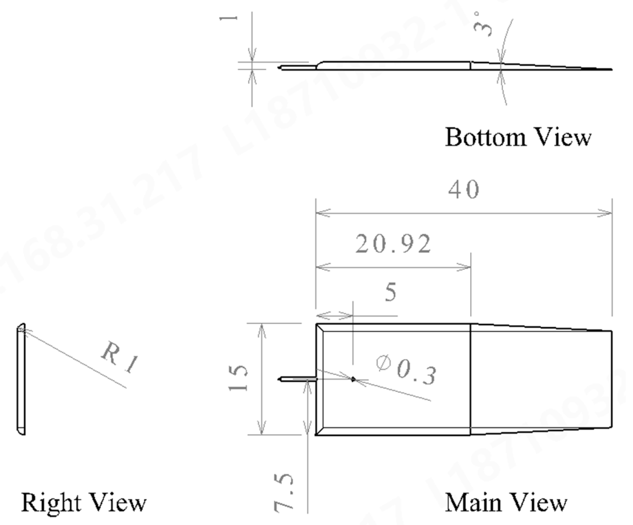
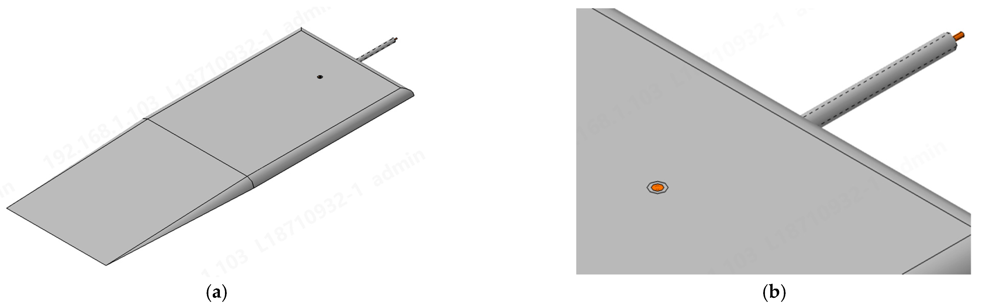
3. Design and Manufacture of the MEMS Pressure Sensor

During the structural optimization of MEMS fibre-optic FP pressure sensor configurations, previous research [47] shows that a ramp structure can minimize flow interference in ultra-thin pressure sensors. Thus, a 1 mm thick encapsulation with a 3° ramp angle was employed. Currently, the adopted 1 mm profile thickness represents the minimum achievable thickness within the industry, and the 3° ramp angle is the smallest feasible angle at this scale. Nevertheless, hydrodynamic characteristics analysis revealed that the frontal curved slope of the sensor may induce water flow deflection effects during hydrodynamic testing. To address this, this study employs a chamfered rectangular cuboid design to establish a gradual slope configuration. Furthermore, a minimum clearance of ≥2 mm was maintained [66] between the sensor’s detection port and slope edges. This effectively reduced flow interference within thickness protrusion regions below critical thresholds, thereby diminishing relative errors in hydrodynamic load measurement data.
Through multiple design iterations, the surface-mounted MEMS fibre-optic FP pressure sensor’s encapsulation patch geometry was optimized, as illustrated in Figure 2. The sensor configuration in Figure 2 features a 1 mm thickness with a minimalist form factor, incorporating a gradual frontal slope with a 3° angle and a 5 mm offset between the sensor port and the distal edge. This design substantially mitigates flow interference effects induced by thickness protrusions during hydrodynamic load testing. Owing to the sensor’s ultra-thin 1 mm profile, current commercial simulation software remains inadequate for reliably modelling the encapsulation design’s influence on hydrodynamic measurement errors. Figure 2 delineates the dimensional specifications of the MEMS fibre-optic FP pressure sensor, while Figure 3 provides a schematic diagram of its assembly.
During fabrication, both the encapsulation patch and metallic tube were fabricated from 316 L stainless steel, selected for its optimal seawater corrosion resistance, and subjected to chromic acid passivation treatment. As shown in Figure 4, the MEMS fibre-optic FP pressure sensor’s port is flush with the encapsulation patch’s surface, and its technical specifications are detailed in Table 1.

4. Experiments

In this experiment, optical pressure sensors (Model: TP01-2M) manufactured by Nanjing Quark Optics Technology Co., Ltd. (Nanjing, China), were selected as the core experimental devices. Comparative experiments were carried out between optical pressure sensors and a conventional high-precision electrical pressure sensor (Model: XPM10-A1). Subsequently, a systematic analysis and evaluation of its performance metrics were conducted to explore the application potential and technical characteristics of this optical pressure sensor in the field of pressure measurement.

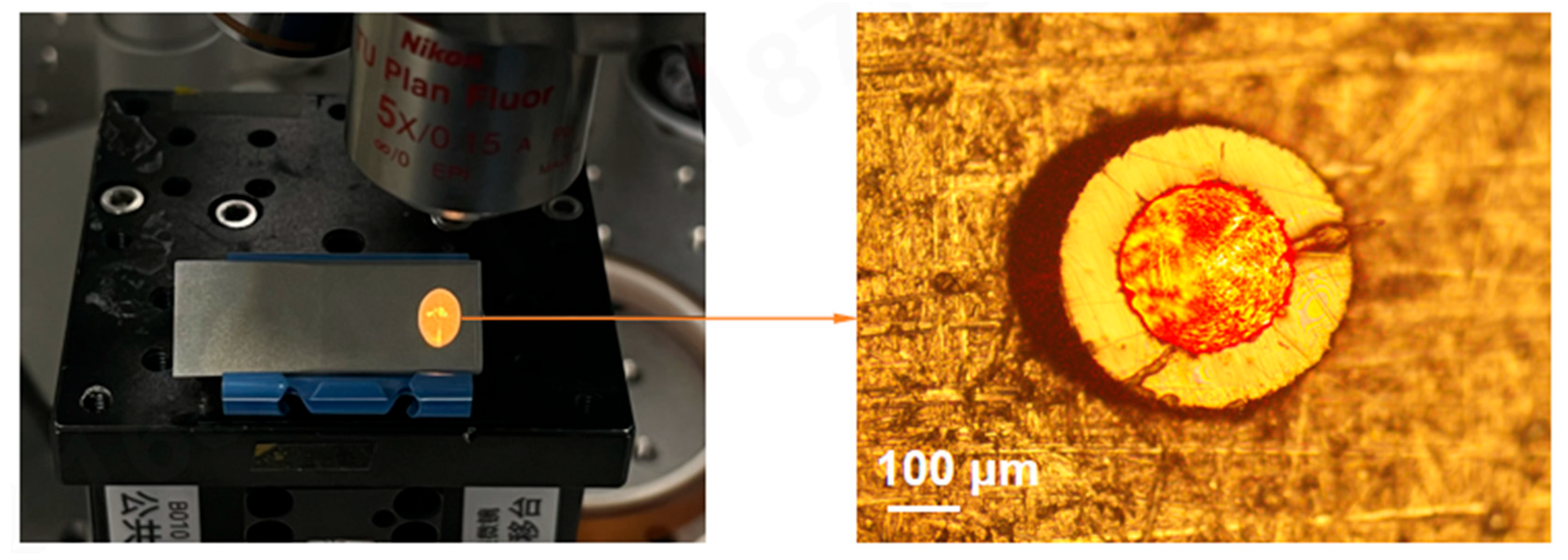
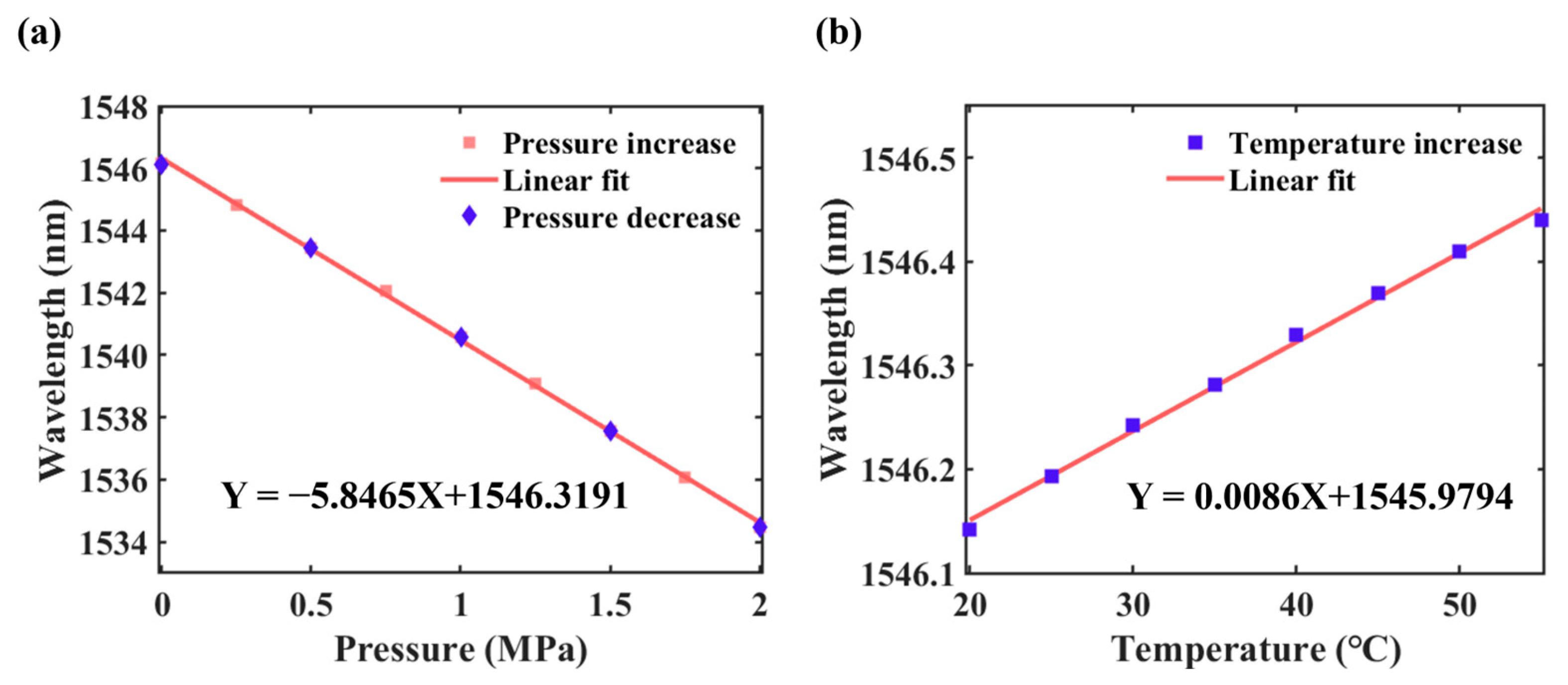
4.1. Calibration of the Optical Pressure Sensor

Figure 5a shows the hydrostatic pressure response of a typical optical pressure sensor in the range of 0∼2 MPa, and the sensitivity is 5.85 pm/kPa. The temperature response of the optical pressure sensor from 20 °C to 55 °C is investigated on a heating platform. The sensor has a linear response to temperature, and its sensitivity is 8.58 pm/°C, leading to a temperature dependence of 1.47 kPa/°C, as illustrated in Figure 5b. These self-developed sensors have undergone independent third-party validations of key metrological attributes, including sensitivity, linearity, and frequency response. When deployed in conjunction with the bespoke demodulation system, these sensors demonstrate a signal acquisition capability extending to 30 kHz. Under 3 kHz high-frequency sinusoidal airwave excitation, their spectral response maintains close conformity with the reference third-party sensors, thereby satisfying hydrodynamic measurement requirements.

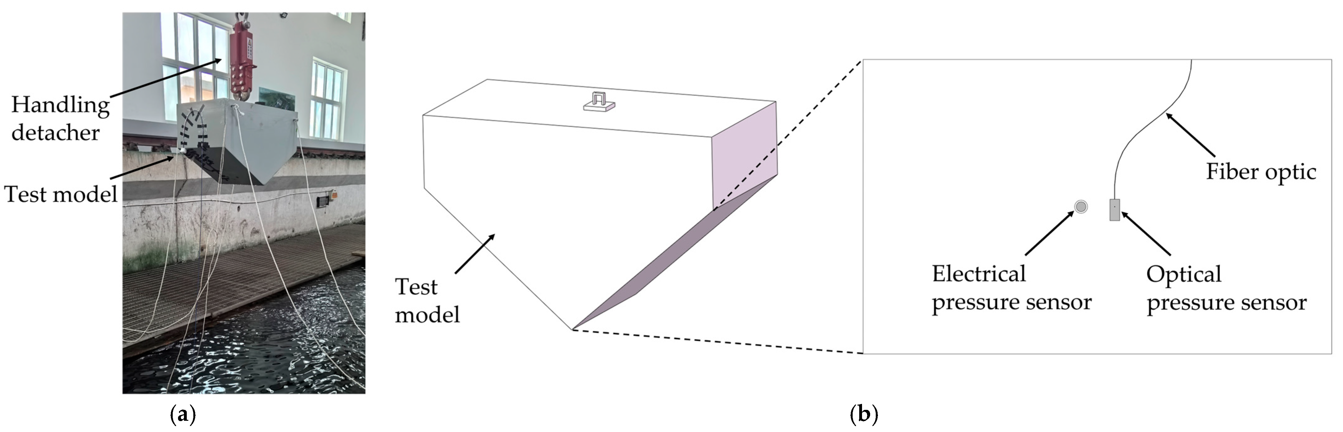
4.2. Water-Entry Test

The experimental system was established to carry out a water-entry test, which mainly includes a wedge-shaped test model, a handling detacher, and a chain block, as illustrated in Figure 6a. In the experimental process, the wedge-shaped test model is first connected to the chain block via the handling detacher. Then, the model is moved to the specified drop height through the chain block. When the water settled, the model was released.
Figure 6b illustrates the positions of pressure sensors. The optical pressure sensor was co-located with an electrical pressure sensor to facilitate concurrent measurements, ensuring a comparative analysis of the water load tests. The electrical pressure sensor was installed across the surface of the wedge-shaped test model by drilling a pressure hole, while the optical pressure sensor was attached to the surface of the model and connected to a self-developed demodulation system via fibre optics. In the present study, the sampling frequency of the pressure signal is set as 30 kHz to capture the peak signals.

4.3. Flight Validation of the Water Landing for the MEMS Measuring System

To systematically evaluate the hydrodynamic impact tolerance characteristics of ultra-thin surface-mounted MEMS fibre-optic FP pressure sensors and their associated surface fibre-optic cables during the water landing of the amphibious aircraft, this study selects typical hull regions subjected to harsh loading conditions with minimal structural damage as test subjects. In consideration of cost-control imperatives, the flight-testing project employs passivated 316 L stainless-steel metallic encapsulation patches (without fibre-optic pressure sensor) as a substitute experimental method.
The configuration of the encapsulation patches is depicted in Figure 7, and these encapsulation patches were bonded using a general high-strength aerospace structural adhesive with a controlled bondline thickness of 0.2 mm tolerance. The adhesive’s bonding strength was subjected to verification under high-pressure water impact conditions. This adhesive exhibits minimal deformation characteristics, with impact-induced measurement errors being negligible.
Furthermore, to acquire hydrodynamic pressure data and systematically validate the process reliability metrics of the hydrodynamic pressure measurement system, three representative measurement points were strategically positioned on the portside for the installation of surface-mounted MEMS fibre-optic FP pressure sensors with integrated optical transmission cables. The spatial routing configuration of the fibre-optic cables is presented in Figure 8. To prevent bend-induced optical transmission losses, the sensor employed bend-insensitive fibre technology. Installation protocols further implement curvature-optimized routing, maintaining a minimum bend radius exceeding 15 times the fibre’s diameter. Transmission fibres are encapsulated with high-strength aerospace structural adhesives on the hull of aircraft skin, significantly reducing measurement errors induced by impact deformation. Temperature-induced measurement errors are compensated via structurally identical temperature sensors to monitor thermal variations, enabling the real-time correction of pressure measurement drift.
After installation, several technical anomalies were identified: Both MEMS fibre-optic FP pressure sensors before the step exhibited abnormal operational conditions. Both operational failure cases originated from improper handling during installation. The first instance involved fibre breakage due to the inadequate protection of the fusion splice point, whilst the second resulted from measurement port blockage caused by aviation adhesive contact and curing. Only the MEMS fibre-optic FP pressure sensor after the step met the flight test criteria. The sensors have undergone rigorous validation, including high-pressure water impact resistance, vibration resistance, corrosion resistance, and cyclic immersion trials, while maintaining optimal performance. Consequently, operational reliability under extreme environmental conditions is robustly guaranteed.

5. Results

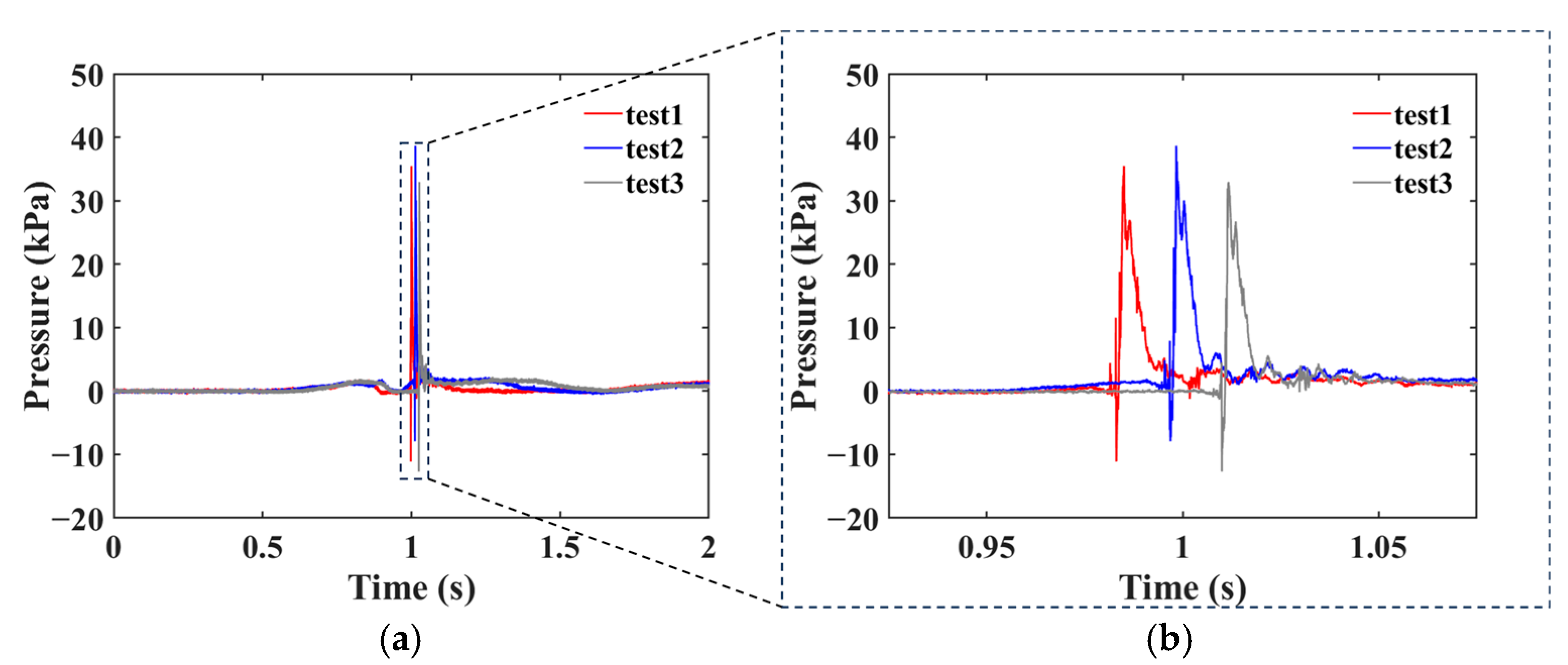
5.1. Water-Entry Test

In the water-entry tests, the distance above the calm water level was set to 1500 mm. The wedge-shaped test model went through four stages, including free-falling, slamming, submersion, and fluid backwashing. As illustrated in Figure 9a, three peak signals of pressure were captured by the proposed optical pressure sensor. The colours red, blue, and grey represent test 1–3, respectively. Figure 9b illustrates the results after stretching the time coordinate, making it easier to see the transient pressure changes, and the results show that they are essentially consistent. Table 2 shows a comparison of the peak pressure signals obtained by optical and electrical sensors, and the experimental results of the optical sensor are in good agreement with those of the electrical sensor, showing the superior response and detection accuracy of the proposed optical pressure sensor. The sensor positioning and difference in the angle of entry of the test model may have an impact on the discrepancy of peak pressure signals.
During water-entry tests, observed measurement deviations between the optical and electrical sensors were primarily caused by sensor placement and entry attitude. Electrical sensors of the same model were installed at equal distances on both sides of the optical sensor. Multiple tests revealed that when the model exhibited tilted attitude upon water contact, substantial measurement divergence occurred between the optical and two electrical sensors. Conversely, during neutral-attitude entries, all three sensors yielded closely aligned measurements.

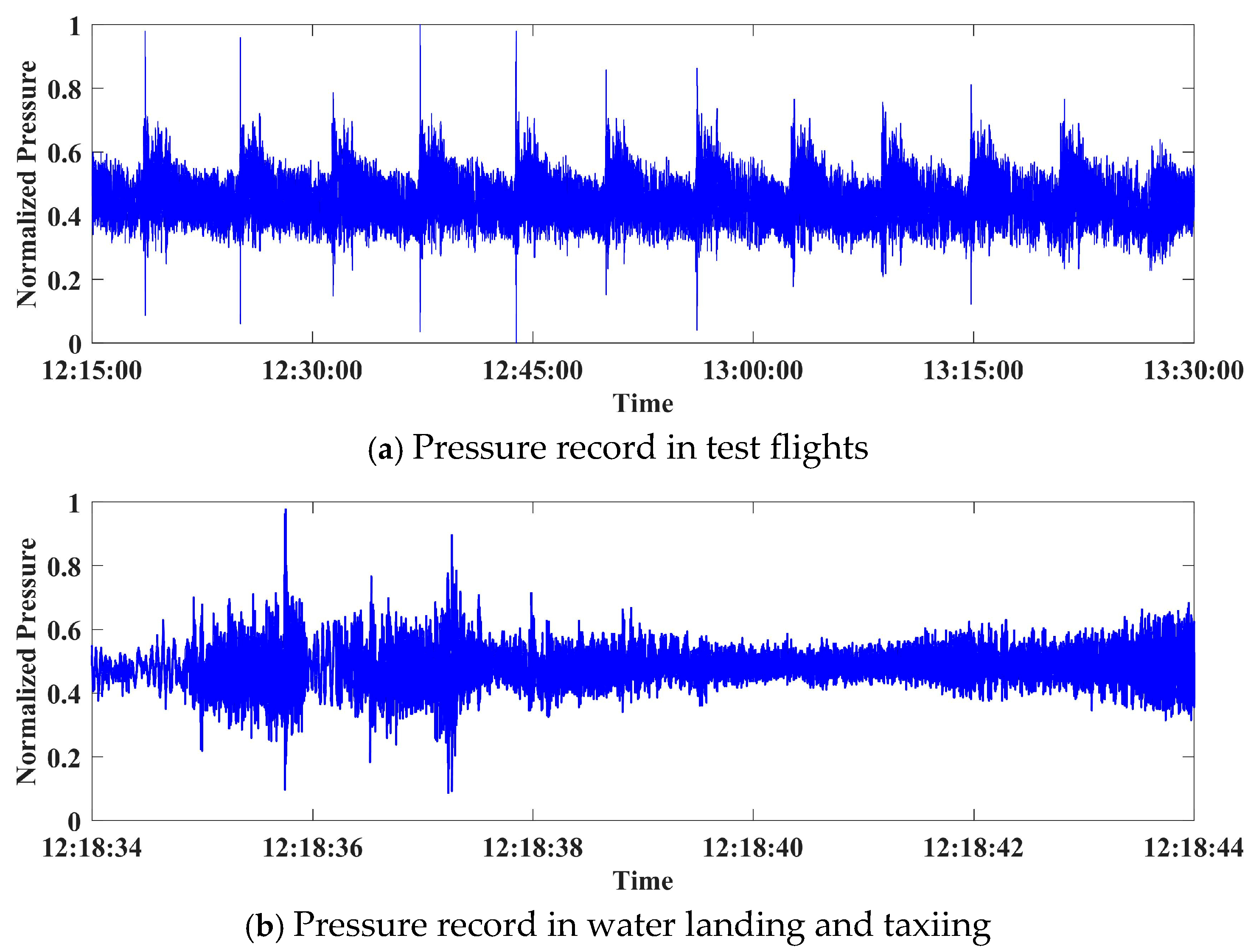
5.2. Flight Validation of the Water Landing for the MEMS Measuring System

For the process reliability verification of ultra-thin surface-mounted fibre-optic pressure sensing systems, this study conducted systematic hydrodynamic load flight testing using a large amphibious aircraft prototype at the Zhanghe Reservoir, Jingmen, Hubei Province. The completion of multiple high-speed water taxiing trials, 12 water take-off/landing missions, and comprehensive shore-based inspections revealed the following: All bonded surface-mounted patches and three MEMS fibre-optic FP sensor arrays maintained intact installation integrity. Both pressure sensing units before and after the step demonstrated uninterrupted signal transmission, with the fibre-optic network exhibiting zero fracture failure. Full pressure dataset acquisition was achieved for the pressure sensor after the step. Figure 10 presents the normalized pressure curves of the amphibious prototype for the test flight and during water landing and taxiing phases, with response profiles derived through the non-filtered direct extraction of pressure peak signals (sampling frequency: 30 kHz).
The experimental data analysis indicates that hydrodynamic pressure exhibited impulsive characteristics, complicating validity assessment, whereas aerodynamic parameters demonstrated clear temporal evolution patterns, effectively excluding electromagnetic interference effects. Technical diagnosis attributes this anomaly to the first frame of the region after the step operating within a gas–liquid two-phase mixed flow field, where multiphase interactions significantly amplify the hydrodynamic pressure analysis’s complexity. Consequently, subsequent pressure sensor installations should avoid the first frame of the post-step region to ensure measurement fidelity.

6. Conclusions

This study presents a novel ultra-thin surface-mounted MEMS fibre-optic FP pressure sensor for the in situ monitoring of hydrodynamic pressure on the hull of large amphibious aircraft. First of all, a hydrodynamic profile encapsulation method for the ultra-thin surface-mounted MEMS fibre-optic FP pressure sensor was introduced, achieving stringent dimensional control with a characteristic thickness of ≤1.0 mm. This innovation effectively suppresses local vortex generation at measurement interfaces through the boundary layer’s optimization.
Secondly, the calibration’s experimental characterization demonstrates that the ultra-thin surface-mounted MEMS fibre-optic FP pressure sensor has an exceptional linear response (nonlinearity error of ≤0.5% F.S.) across the −100 kPa to 2 MPa range, with hydrostatic calibration revealing a sensitivity of 5.85 pm/kPa and temperature coefficient limited to 1.47 kPa/°C. Theoretical dynamic analysis confirms that the operational bandwidth of the frequency response exceeds 2 MHz, fulfilling transient hydrodynamic impact event capture requirements for large amphibious aircraft applications. The ultra-thin structure enables high-density array configuration on wedge-shaped surfaces, establishing a robust hardware platform for distributed hydrodynamic load characterization.
For the water-entry test of the wedge-shaped body, the measurement data met predefined technical specifications in consistency, stability, and repeatability metrics. A cross-verification framework employing an electrical sensor validated that the MEMS fibre-optic system’s hydrodynamic response bandwidth fully encompasses the 0–10 kHz operational demands of the water-entry test.
The flight validation of the water landing of the amphibious prototype conclusively validated the process reliability of the MEMS measuring system under high-speed water impact conditions during water landing. It can be confirmed that the feasibility of the ultra-thin surface-mounted MEMS fibre-optic FP pressure sensor array bonded by aerospace structural adhesives can be applied for the in situ monitoring of full-scale hydrodynamic pressure measurements on the hull of large amphibious aircraft during water landings. The flight test results show that this ultra-thin surface-mounted MEMS fibre-optic FP pressure sensor exhibits superior robustness in extreme environments compared to traditional invasive electrical sensors.

Author Contributions

Conceptualization, T.F. and Y.C.; methodology, X.C.; software, X.C.; validation, X.C. and B.W.; formal analysis, T.F. and X.C.; data curation, T.F. and Y.C.; writing—original draft preparation, T.F. and X.C.; writing—review and editing, T.F., Y.C. and F.X.; supervision, F.X. and L.H.; project administration, B.W.; funding acquisition, T.F. and L.H. All authors have read and agreed to the published version of the manuscript.

Funding

This research was funded by AVIC General Huanan Aircraft Industry Co., Ltd., grant number HNZL-2023-02 and HN20240162.

Institutional Review Board Statement

Not applicable.

Informed Consent Statement

Not applicable.

Data Availability Statement

Data are contained within the article.

Acknowledgments

The authors would like to express their sincere gratitude to AVIC General Huanan Aircraft Industry Co., Ltd., for providing a large amphibious aircraft prototype for flight tests of water landings. At the same time, they would like to express their heartfelt appreciation to all personnel involved in the water-entry tests, design modifications for the flight tests, installation work, and on-site flight test support services. Additionally, the first author of this study, T.F., would like to express his special gratitude to his postdoctoral supervisor, General Designer H.L., who, despite facing widespread doubts about the test technology and the sensor bonding installation plan before the test flight, still offered unwavering trust and support.

Conflicts of Interest

Author Tianyi Feng was employed by the company AVIC General Huanan Aircraft Industry Co., Ltd. The remaining authors declare that the research was conducted in the absence of any commercial or financial relationships that could be construed as a potential conflict of interest.

References

  1. Qiu, L.; Song, W. Efficient Multiobjective Optimization of Amphibious Aircraft Fuselage Steps with Decoupled Hydrodynamic and Aerodynamic Analysis Models. J. Aerosp. Eng. 2016, 29, 04015071. [Google Scholar] [CrossRef]
  2. Qiu, L.; Song, W. Efficient Decoupled Hydrodynamic and Aerodynamic Analysis of Amphibious Aircraft Water Takeoff Process. J. Aircr. 2013, 50, 1369–1379. [Google Scholar] [CrossRef]
  3. Lyu, J.; Yang, R.; Huang, L. Structure Dynamic Response of Amphibious Aircraft Induced by Water-Taxiing. Int. J. Aerosp. Eng. 2021, 2021, 6104407. [Google Scholar] [CrossRef]
  4. Cui, B.; Zhang, Y.; Dong, H.; Jin, T.; Zhang, C.; Zhu, Q. Test and numerical analysis for water entry of elastic cabin from amphibious aircraft. Aerosp. Sci. Technol. 2024, 150, 109168. [Google Scholar] [CrossRef]
  5. Seddon, C.M.; Moatamedi, M. Review of water entry with applications to aerospace structures. Int. J. Impact Eng. 2006, 32, 1045–1067. [Google Scholar] [CrossRef]
  6. Zhou, H.; Hu, K.; Mao, L.; Sun, M.; Cao, J. Research on planing motion and stability of amphibious aircraft in waves based on cartesian grid finite difference method. Ocean. Eng. 2023, 272, 113848. [Google Scholar] [CrossRef]
  7. Ning, D.S.; Shi, Y.J.; Zhang, G.Y.; Wang, H.; Hu, H.; Zhang, Z.F. Numerical research on slamming characteristics of aircraft landing on water. J. Hydrodyn. 2023, 35, 171–184. [Google Scholar] [CrossRef]
  8. Liu, X.; Tan, L.; Zhang, X.; Li, L. Research of Slamming Load Characteristics during Trans-Media Aircraft Entry into Water. Drones 2024, 8, 89. [Google Scholar] [CrossRef]
  9. Huera-Huarte, F.J.; Jeon, D.; Gharib, M. Experimental investigation of water slamming loads on panels. Ocean. Eng. 2011, 38, 1347–1355. [Google Scholar] [CrossRef]
  10. Panciroli, R.; Biscarini, C.; Falcucci, G.; Jannelli, E.; Ubertini, S. Live monitoring of the distributed strain field in impulsive events through fiber Bragg gratings. J. Fluids Struct. 2016, 61, 60–75. [Google Scholar] [CrossRef]
  11. Faltinsen, O. Sea Loads on Ships and Offshore Structures; Cambridge University Press: Cambridge, UK, 1993; Volume 1. [Google Scholar]
  12. Faltinsen, O.M. Hydrodynamics of High-Speed Marine Vehicles; Cambridge University Press: Cambridge, UK, 2005. [Google Scholar]
  13. Von Karman, T. The Impact on Seaplane Floats During Landing; Aerodynamical Institute of RWTH Aachen University: Aachen, Germany, 1929. [Google Scholar]
  14. Dobrovol’Skaya, Z. On some problems of similarity flow of fluid with a free surface. J. Fluid Mech. 1969, 36, 805–829. [Google Scholar] [CrossRef]
  15. Zhuo, Y.; Chen, L.; Su, S.; Li, S.; Chen, X. Research on the application of airbag loading technology in the strength test of amphibious aircraft. J. Phys. Conf. Ser. 2024, 2819, 012037. [Google Scholar] [CrossRef]
  16. Wagner, H. Über stoß-und gleitvorgänge an der oberfläche von flüssigkeiten. ZAMM J. Appl. Math. Mech. 1932, 12, 193–215. [Google Scholar] [CrossRef]
  17. Korobkin, A.; Gueret, R.; Malenica, Š. Hydroelastic coupling of beam finite element model with Wagner theory of water impact. J. Fluids Struct. 2006, 22, 493–504. [Google Scholar] [CrossRef]
  18. Singh, S.P.; Sen, D. A comparative study on 3D wave load and pressure computations for different level of modelling of nonlinearities. Mar. Struct. 2007, 20, 1–24. [Google Scholar] [CrossRef]
  19. Hirdaris, S.E.; Bai, W.; Dessi, D.; Ergin, A.; Gu, X.; Hermundstad, O.A.; Huijsmans, R.; Iijima, K.; Nielsen, U.D.; Parunov, J.; et al. Loads for use in the design of ships and offshore structures. Ocean. Eng. 2014, 78, 131–174. [Google Scholar] [CrossRef]
  20. Lakshmynarayanana, P.A.K.; Hirdaris, S. Comparison of nonlinear one- and two-way FFSI methods for the prediction of the symmetric response of a containership in waves. Ocean. Eng. 2020, 203, 107179. [Google Scholar] [CrossRef]
  21. Jiao, J.; Chen, Z.; Chen, C.; Ren, H. Time-domain hydroelastic analysis of nonlinear motions and loads on a large bow-flare ship advancing in high irregular seas. J. Mar. Sci. Technol. 2020, 25, 426–454. [Google Scholar] [CrossRef]
  22. Datta, R.; Guedes Soares, C. Analysis of the hydroelastic effect on a container vessel using coupled BEM–FEM method in the time domain. Ships Offshore Struct. 2020, 15, 393–402. [Google Scholar] [CrossRef]
  23. Zhang, G.; Feng, S.; Zhang, Z.; Chen, Y.; Sun, Z.; Zong, Z. Investigation of hydroelasticity in water entry of flexible wedges with flow detachment. Ocean. Eng. 2021, 222, 108580. [Google Scholar] [CrossRef]
  24. Jiao, J.; Huang, S.; Tezdogan, T.; Terziev, M.; Soares, C.G. Slamming and green water loads on a ship sailing in regular waves predicted by a coupled CFD–FEA approach. Ocean. Eng. 2021, 241, 110107. [Google Scholar] [CrossRef]
  25. Sun, J.Y.; Sun, S.L.; Zhang, Z.L.; Ren, H.L. Water entry of a seaplane section considering the wave effect. Phys. Fluids 2024, 36, 082115. [Google Scholar] [CrossRef]
  26. Xu, G.D.; Duan, W.Y.; Wu, G.X. Numerical simulation of oblique water entry of an asymmetrical wedge. Ocean. Eng. 2008, 35, 1597–1603. [Google Scholar] [CrossRef]
  27. Ma, S.; Mahfuz, H. Finite element simulation of composite ship structures with fluid structure interaction. Ocean. Eng. 2012, 52, 52–59. [Google Scholar] [CrossRef]
  28. Shadloo, M.S.; Oger, G.; Le Touzé, D. Smoothed particle hydrodynamics method for fluid flows, towards industrial applications: Motivations, current state, and challenges. Comput. Fluids 2016, 136, 11–34. [Google Scholar] [CrossRef]
  29. Krastev, V.K.; Facci, A.L.; Ubertini, S. Asymmetric water impact of a two dimensional wedge: A systematic numerical study with transition to ventilating flow conditions. Ocean. Eng. 2018, 147, 386–398. [Google Scholar] [CrossRef]
  30. Xie, H.; Ren, H.; Qu, S.; Tang, H. Numerical and experimental study on hydroelasticity in water-entry problem of a composite ship-hull structure. Compos. Struct. 2018, 201, 942–957. [Google Scholar] [CrossRef]
  31. Facci, A.L.; Panciroli, R.; Ubertini, S.; Porfiri, M. Assessment of PIV-based analysis of water entry problems through synthetic numerical datasets. J. Fluids Struct. 2015, 55, 484–500. [Google Scholar] [CrossRef]
  32. Facci, A.L.; Ubertini, S. Numerical Assessment of Similitude Parameters and Dimensional Analysis for Water Entry Problems. Math. Probl. Eng. 2015, 2015, 324961. [Google Scholar] [CrossRef]
  33. Duan, X.; Sun, W.; Chen, C.; Wei, M.; Yang, Y. Numerical investigation of the porpoising motion of a seaplane planing on water with high speeds. Aerosp. Sci. Technol. 2019, 84, 980–994. [Google Scholar] [CrossRef]
  34. Sun, H.; Kasdin, N.J.; Vanderbei, R. Identification and adaptive control of a high-contrast focal plane wavefront correction system. J. Astron. Telesc. Instrum. Syst. 2018, 4, 049006. [Google Scholar] [CrossRef]
  35. Shihua, J.M.; Liem, R.P.; Li, Y. An Improved Experimental Framework of Amphibious Marine Vehicle Hull Hydrodynamics. IEEE J. Ocean. Eng. 2023, 49, 80–91. [Google Scholar] [CrossRef]
  36. Zong, Z.; Sun, Y.; Jiang, Y.; Sun, T.; Yu, Y. Evolution of slamming load and flow field in water-entry process of trimaran ship section. Ocean. Eng. 2020, 205, 107319. [Google Scholar] [CrossRef]
  37. Yu, P.; Xie, H.; Liu, F.; Li, P.; Cheng-Lv, G. Numerical investigation on the water entry of a 2D seaplane section with heel angles. Ocean. Eng. 2022, 262, 112236. [Google Scholar] [CrossRef]
  38. Wang, S.; Soares, C.G. Stern slamming of a chemical tanker in irregular head waves. Ocean. Eng. 2016, 122, 322–332. [Google Scholar] [CrossRef]
  39. Wang, F.Z.; Animasaun, I.L.; Muhammad, T.; Okoya, S.S. Recent advancements in fluid dynamics: Drag reduction, lift generation, computational fluid dynamics, turbulence modelling, and multiphase flow. Arab. J. Sci. Eng. 2024, 49, 10237–10249. [Google Scholar] [CrossRef]
  40. Jiang, C.X.; Shuai, Z.J.; Zhang, X.Y.; Li, W.Y.; Li, F.C. Numerical study on the transient behavior of water-entry supercavitating flow around a cylindrical projectile influenced by turbulent drag-reducing additives. Appl. Therm. Eng. 2016, 104, 450–460. [Google Scholar] [CrossRef]
  41. Chen, J.; Li, L.; Fu, X.; Xiao, T.; Wu, B.; Tong, M. Scale effect on wave planing performance of amphibious aircraft at constant speed. Aerosp. Sci. Technol. 2024, 148, 109083. [Google Scholar] [CrossRef]
  42. Ghodoosipour, B.; Stolle, J.; Nistor, I.; Mohammadian, A.; Goseberg, N. Experimental study on extreme hydrodynamic loading on pipelines part 2: Induced force analysis. J. Mar. Sci. Eng. 2019, 7, 262. [Google Scholar] [CrossRef]
  43. Reed, S.; Holford, D. Guidance for aircraft operational loads measurement programmes. Mil. Aircr. Struct. Airworth. Advis. Group Pap. 2007, 109, 31. [Google Scholar]
  44. Huang, S.; Jiao, J.; Chen, C. Numerical prediction of ship motion and slamming load characteristics in cross wave. J. Mar. Sci. Technol. 2022, 27, 104–124. [Google Scholar] [CrossRef]
  45. Brewick, P.T.; Ibrahim, A.M.; Hutchinson, M.; Morgan, J. Using surrogate models and mechanics to predict pressure from strain data. Ocean. Eng. 2022, 261, 112064. [Google Scholar] [CrossRef]
  46. Chuang, W.-L. Experimental investigation on fluid kinematics and impact pressure of flat plate impacts on pure and aerated water. Ocean. Eng. 2022, 266, 112837. [Google Scholar] [CrossRef]
  47. Fukushima, H.; Wakahara, M.; Kanai, T. Hull Surface Pressure Measurement of the Affix-Type Multipoint Pressure Sensor Using Fiber Bragg Gratings. In Practical Design of Ships and Other Floating Structures, Proceedings of the 14th International Symposium, PRADS 2019, Yokohama, Japan, 22–26 September 2019; Springer: Berlin, Germany, 2021; Volume I. [Google Scholar]
  48. Hu, Q.; Wang, M.Z.; Wu, B.; Zhang, J.X.; Xiao, Z. The Application of Overset Grid in the Analysis of Impact Loads of Amphibious Aircraft during Landing on the Water. IOP Conf. Ser. Mater. Sci. Eng. 2020, 751, 012032. [Google Scholar] [CrossRef]
  49. Huang, M.; Wu, B.; Li, C. The water impact load study for seaplane during get-off and alighting process on rough water. J. Phys. Conf. Series. 2022, 2282, 012024. [Google Scholar] [CrossRef]
  50. Doll, U.; Migliorini, M.; Baikie, J.; Zachos, P.K.; Röhle, I.; Melnikov, S.; Steinbock, J.; Dues, M.; Kapulla, R.; MacManus, D.G.; et al. Non-intrusive flow diagnostics for unsteady inlet flow distortion measurements in novel aircraft architectures. Prog. Aerosp. Sci. 2022, 130, 100810. [Google Scholar] [CrossRef]
  51. Nila, A.; Vanlanduit, S.; Vepa, S.; Van Paepegem, W. A PIV-based method for estimating slamming loads during water entry of rigid bodies. Meas. Sci. Technol. 2013, 24, 045303. [Google Scholar] [CrossRef]
  52. CCAR-25-R4; Airworthiness Standards: Transport Category Airplanes. Civil Aviation Administration of China: Beijing, China, 2011. (In Chinese)
  53. Guo, Y.P.; Joshi, M.C.; Bent, P.H.; Yamamoto, K.J. Surface pressure fluctuations on aircraft flaps and their correlation with far-field noise. J. Fluid Mech. 2000, 415, 175–202. [Google Scholar] [CrossRef]
  54. Yuan, S.; Li, Y.; Bao, F.; Xu, H.; Yang, Y.; Yan, Q.; Zhong, S.; Yin, H.; Xu, J.; Huang, Z.; et al. Marine environmental monitoring with unmanned vehicle platforms: Present applications and future prospects. Sci. Total Environ. 2023, 858, 159741. [Google Scholar] [CrossRef]
  55. Abrate, S. Hull slamming. Appl. Mech. Rev. 2011, 64, 060803. [Google Scholar] [CrossRef]
  56. Song, Y.; Xia, L.; Wu, Y. The interrogation of quasi-distributed optical FBG sensing system through adopting a wavelength-tunable fiber chaotic laser. J. Light. Technol. 2019, 37, 2435–2442. [Google Scholar] [CrossRef]
  57. Zhang, Q.; Lei, J.; Chen, Y.; Wu, Y.; Chen, C.; Xiao, H. 3D printing of all-glass fiber-optic pressure sensor for high temperature applications. IEEE Sens. J. 2019, 19, 11242–11246. [Google Scholar] [CrossRef] [PubMed]
  58. Liu, J.; Guo, G. A FBG inclinometer for simultaneous measurement of horizontal deformation and sudden deformation. IEEE Trans. Instrum. Meas. 2021, 70, 7503410. [Google Scholar]
  59. Wang, J.; Li, Z.; Fu, X.; Wang, H.; Jiang, D. Distributed temperature sensing system based on a densely spaced FBG array for small fire recognition. Measurement 2021, 179, 109406. [Google Scholar] [CrossRef]
  60. Xu, H.; Li, F.; Gao, Y.; Wang, W. Simultaneous measurement of tilt and acceleration based on FBG sensor. IEEE Sens. J. 2020, 20, 14857–14864. [Google Scholar] [CrossRef]
  61. Xu, H.; Wang, W.; Li, F.; Du, Y.; Tu, H.; Guo, C. Railway slope monitoring based on dual-parameter FBG sensor. Photonic Sens. 2025, 15, 250121. [Google Scholar] [CrossRef]
  62. Waskito, K.T.; Kashiwagi, M.; Iwashita, H.; Hinatsu, M. Prediction of nonlinear vertical bending moment using measured pressure distribution on ship hull. Appl. Ocean. Res. 2020, 101, 102261. [Google Scholar] [CrossRef]
  63. Xu, G.; He, B.; Li, H.; Gui, X.; Li, Z. FBG pressure sensor in pressure distribution monitoring of ship. Opt. Express 2022, 30, 21396–21409. [Google Scholar] [CrossRef]
  64. Chen, Y.; Lu, D.; Xing, H.; Ding, H.; Luo, J.; Liu, H.; Kong, X.; Xu, F. Recent progress in MEMS fiber-optic Fabry–Perot pressure sensors. Sensors 2024, 24, 1079. [Google Scholar] [CrossRef]
  65. Kienitz, S.U.; Lohr, L.; Schmid, M.J.; Koch, A.W. Static and dynamic pressure measurement in flight test application with optical Fabry–Pérot sensors. IEEE Trans. Instrum. Meas. 2021, 70, 7004611. [Google Scholar] [CrossRef]
  66. Fadaei Rodi, R.; Kamali, H.A.; Pasandidehfard, M. Innovative optimization of parabolic cavitators: Improving hydrodynamic efficiency and supercavity qualitycavitatio. Phys. Fluids 2024, 36, 103356. [Google Scholar] [CrossRef]
Figure 1. (a) Schematic diagram of the MEMS fibre-optic FP pressure sensor; (b) cross-sectional view of the cavity structure.
Photonics 12 00627 g001
Figure 2. Surface-mounted MEMS fibre-optic FP pressure sensor’s dimensions.
Photonics 12 00627 g002
Figure 3. Schematics of (a) the overall design; (b) local magnified MEMS fibre-optic FP pressure sensor port.
Photonics 12 00627 g003
Figure 4. Re-encapsulated MEMS fibre-optic FP pressure sensor.
Photonics 12 00627 g004
Figure 5. Calibration of the pressure sensor: (a) the pressure response of the sensor in the range of 0∼2 MPa; (b) the temperature response of the sensor from 20 °C to 55 °C.
Photonics 12 00627 g005
Figure 6. The experimental system: (a) sketch of the experimental system for water-entry tests; (b) illustration of pressure sensors’ positions.
Photonics 12 00627 g006
Figure 7. Schematic of the installation position of patches.
Photonics 12 00627 g007
Figure 8. Schematic of (a) external optical cables; (b) internal optical cables.
Photonics 12 00627 g008
Figure 9. Optical pressure sensor measurements: (a) three peak signals of pressure captured by the proposed optical pressure sensor; (b) the results after stretching the time coordinate of Figure 6a.
Photonics 12 00627 g009
Figure 10. Normalized pressure data records of (a) flight tests; (b) water landing and taxiing.
Photonics 12 00627 g010
Table 1. Technical specifications of surface-mounted MEMS fibre-optic FP pressure sensors.
RangeCustomizable, −100 kPa to 10 MPa
Dimensions0.3 mm (sensing element)
Sampling FrequencySelectable, 10 kHz–30 kHz
Accuracy0.5% F.S. (customizable down to 0.1% F.S.)
Frequency Response>2 MHz
Resolution0.1% F.S.
Operating Temperature−10 °C to 100 °C
Overload Pressure2× F.S.
Encapsulation Material316 L stainless steel
Encapsulation Thickness1 mm
Connector TypeAngled physical contact (APC)
Table 2. Peak signal comparison.
Test NumberElectrical Sensor Measurements (kPa)Optical Sensor Measurements (kPa)Pressure Deviation (kPa)
135.4336.441.01
236.7038.271.57
334.7732.931.84
Disclaimer/Publisher’s Note: The statements, opinions and data contained in all publications are solely those of the individual author(s) and contributor(s) and not of MDPI and/or the editor(s). MDPI and/or the editor(s) disclaim responsibility for any injury to people or property resulting from any ideas, methods, instructions or products referred to in the content.

