1. Introduction
Exciting atoms to a state with a very high principal quantum number n, the so-called Rydberg state [
1,
2], leads to large dipole moments, which scale as
and have a long lifetime compared with low-lying transitions, which scale as
. These appealing features render the Rydberg atom an ubiquitous tool for use in high-sensitivity detection of microwave electric fields [
3,
4,
5,
6,
7] and in quantum information applications, such as single-photon sources [
8,
9] and quantum computation, [
10,
11,
12,
13,
14] through the incorporation of optical tweezers.
To perform Rydberg excitation, two laser beams are conventionally employed in a ladder-type configuration, resonantly driving the transition between the ground state and the Rydberg states via an intermediate state. In practice, the use of tunable single-frequency diode lasers in combination with a high-power fiber laser amplifier allows for controllable Rydberg excitation in terms of Rydberg state selection and the associated Rabi frequency. Although atomic absorption-based frequency stabilization techniques are generally used in the atomic, molecular, and optical (AMO) physics community, they cannot fulfill the requirements of a narrow linewidth and low technical noise in the Rydberg atom-based applications of precision measurement [
3,
4,
5,
6,
7] and high-fidelity quantum logic gates [
10,
11,
12,
13,
14]. Ultra-stable cavity-stabilized optical reference systems have instead demonstrated the ability to address these challenges [
15]. In these systems, high-reflectivity mirrors are attached to monolithic spacers, which are typically made of ultra-low-expansion (ULE) glass to prevent changes in the cavity length due to external temperature drifts; temperature stabilization and a high-vacuum environment further enhance performance. A single-crystalline silicon cavity [
16] operated at 124 K reached thermal-noise-limited instability at a level of
. Most operations of Rydberg excitation stabilized by ultra-stable cavity reference systems have been so far constrained to laboratories [
17,
18,
19,
20,
21,
22]. However, applications like environmental electric field sensors require a transportable system to enable flexibility in the choice of measurement sites [
23,
24,
25,
26,
27,
28].
Here, we report a portable ultra-stable laser for the Rydberg excitation of . The entire system is installed in a standard 19-inch 22U rack cabinet, which includes two lasers, a beam delivery system, an ultra-stable cavity, and a complete control system consisting of temperature control, cavity locking, signal generators, and a control PC. To achieve transportability, we have created optimized designs for aspects such as cavity installation, optical path coupling, and the heat sink systems. Through testing, it was determined that the system can adapt to external-field temperature changes ranging from 20 °C to 40 °C, and the temperature tolerance is expected to range from 0°C to 50°C. The system was tested in a noisy environment for two hours, and the test results were satisfactory. Practical use shows that after long-distance transportation (over 400 km), the system only requires slight optimization to resume operation.
2. System Assembly
The purpose of this optical reference system is to stabilize two lasers’ resonance with the
atomic transitions
(852 nm) and
(or
) (509 nm), respectively. Taking into account the characteristics of the field test, we installed all the systems in a 22U cabinet. This included two lasers, an ultra-stable cavity, and all the control components. As shown in
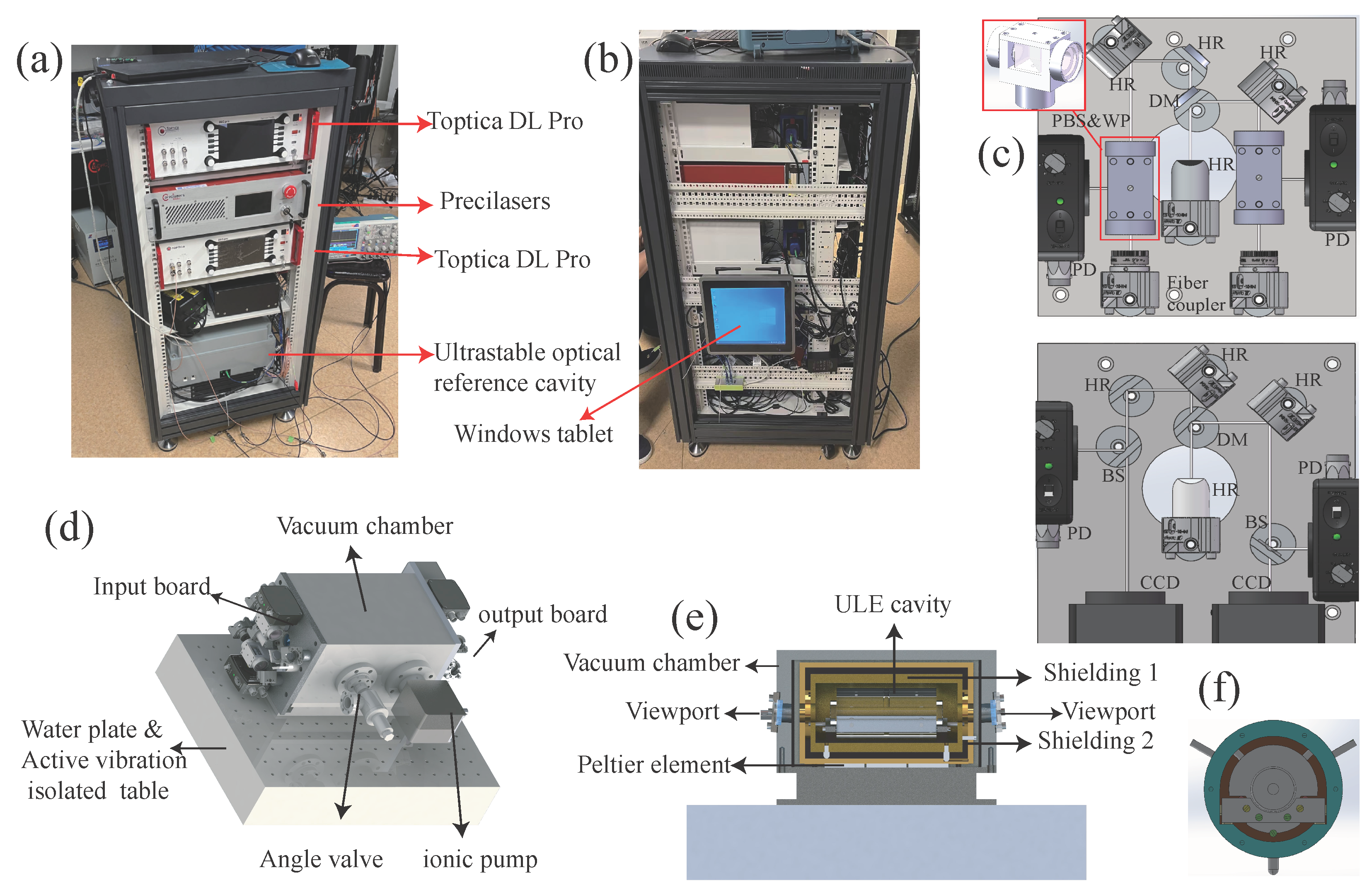
Figure 1a, the laser controllers consist of two controllers for Toptica lasers and a controller for Precilasers fiber amplification and frequency doubling, which occupy around half of the cabinet space. The lasers and the Beamsplitter Kits system (PFS-FFT-1X2, Thorlabs, Newton, NJ, USA) are installed at the back zone of the cabinet, and are not shown in the picture. The 852 nm laser is produced by a tunable single-frequency diode laser (DL Pro, Toptica, Gräfelfing, Germany), while the 509 nm laser is generated via frequency doubling of the 1018 nm laser, and the 1018 nm laser is produced by a tunable single-frequency diode laser (Toptica DL Pro) and amplified by a high-power fiber amplifier (Precilaser, Berrioplano, Spain). A small amount of 852 nm and 1018 nm light (by Beamsplitter Kits, Thorlabs, Newton, NJ, USA) is picked up and then directed into the reference cavity for laser locking.
There are also many control components in the system, such as the ion pump controller for maintaining the vacuum, the temperature controller for maintaining the cavity temperature, the controller of the vibration isolation system, the signal source of the locking system, the locking controller, the detector power supply, etc. We placed these systems below the laser controller and above the ultra-stable cavity, which occupy approximately 10% of the cabinet space. In the system, the radio frequency signals, locking modules, cavity mode monitoring, 1018 frequency doubling, etc., are all controlled by a Windows tablet (SK-12ZLGKSH, Kechu, Shanghai, China), as shown in
Figure 1b.
In order to avoid light and dust pollution, the ultra-stable cavity is encapsulated within an aluminum casting shell. The overall size of the encapsulated system is 400 mm × 300 mm × 185 mm. The system is set upon an active vibration isolation platform (Accurion Nano30) with a size of 400 mm × 300 mm × 75 mm, which features an active bandwidth of 1 Hz–200 Hz and passive isolation beyond 200 Hz. The encapsulated ultra-stable cavity is placed at the bottom of the system, occupying the remaining 8U of space. When testing the system, we found that due to the effect of large fluctuations in the temperature of the environment, the temperature-control system could collapse. In order to obtain a wider temperature-tolerance range, a water-cooled heat dissipation plate was added. The water cooling system is used to control the temperature of the entire system’s housing. A rough test showed that the system can work well within a temperature range of 20 °C to 40 °C. We expect that high-precision temperature-control effects can be achieved in an external environment with a temperature range of 0 °C to 50 °C.
2.1. Cavity, Optical Light Path, and Vacuum Design
Two cavity mirrors were double-coated at 852 nm and 1018 nm: one was a concave mirror with a radius of curvature of 500 mm, and the other was a plane mirror. Both mirrors were high-reflectivity-coated (, for concave mirror, and , for plane mirror; purchased from FiveNine optics company, Boulder, CO, USA) for high-finesse purposes. The cavity finesse was calculated as and . The two cavity mirrors were connected by a 10 cm spacer. Both ends of the spacer were polished, and a parallelism of less than 10 arcminutes was achieved. The cavity mirrors and the spacer were connected by optical cementing. The free spectral range of the cavity corresponding to this cavity length is 1.5 GHz.
Before building the optical path, we obtained optimal mode-matching for the waist of the cavity of 509 µm @ 1018 nm and 466 µm @852 nm by numerical simulation. Through Gaussian beam transformation formula calculations, we selected a 4.6 mm adjustable fiber-coupler for mode matching. The total length of the optical path is within 300 mm. This minimizes the number of optical components and ensures cavity mode matching with the shortest possible optical path, thus guaranteeing the stability of the system. In addition, to minimize the instability factors of the system, we built the input- and output-coupling optical paths on two aluminum plates with dimensions of 120 mm × 120 mm × 10 mm, as shown in
Figure 1c, and fixed these two aluminum plates at the two ends of the vacuum.
To maximize the stability of the system, we took several aspects into consideration. Firstly, we used adjustable mounts as little as possible in the system. There are only two adjustable mirror mounts (MHX-12.7A, Sigmakoki, Japan) in each mode-matching optical path. The height of the optical path in the system is approximately 25 mm, and the distance between the fiber output-coupling head and the vacuum chamber is about 170 mm. In addition, during the system installation, we applied screw-locking adhesive (Loctite 290) to all screws to ensure that the system could remain in place even after long-term exposure to vibrations. In front of the input couplers are fiber-coupled electro-optic modulators (EOM) (KY-PM-08-10G-PP-FAKY-PM-08-10G-PP-FA, Keyang Photonics, China) for modulation. Therefore, after the system is properly adjusted, we can encapsulate the fiber EOM and the ultra-stable cavity together, leaving the input end of the fiber EOM as the packaging interface.
The 10 cm long ULE glass cavity is housed in a vacuum system with a 5 L/s ion pump (B2020-5L5LA, Limit Vacuum Techology, Beijing, China) to maintain the pressure at the
Pa level. The cutting position provides support and rotational limitation for the cavity. At the same time, a set of three limiting screws are arranged at equal angular positions in the axial direction of the cavity, and two sets of such limiting screws are set in the axial direction. In addition, three pairs of limiting screws are added on the two parallel surfaces of the cavity, which ensures that the displacement and rotation of the system are as small as possible during transportation and collisions. The vacuum system consists of three-layer shielded structure. The innermost layer is a structure with copper plated with gold, which provides thermal shielding for the inner layer. The middle layer is an Invar structure, which provides stable support and temperature control. The outermost layer is an aluminum alloy vacuum chamber, which provides a vacuum environment. Three Peltier elements are placed between the second-layer shield and the vacuum chamber, and a thermistor is placed in the second-layer structure for temperature control.
Figure 1e illustrates the vacuum assembly designed by us. The cavity is placed inside a two-stage heat shield, which is actively temperature-stabilized at the zero-crossing point (26 °C) by a commercial digital PID controller (TED200c, Thorlabs, Newton, NJ, USA).
2.2. ULE Cavity’s Support Structure
We designed and fabricated a notched ULE glass cavity with square “cutouts” on the underside of a cylindrical spacer, as shown in
Figure 2a. The notched cavity [
29,
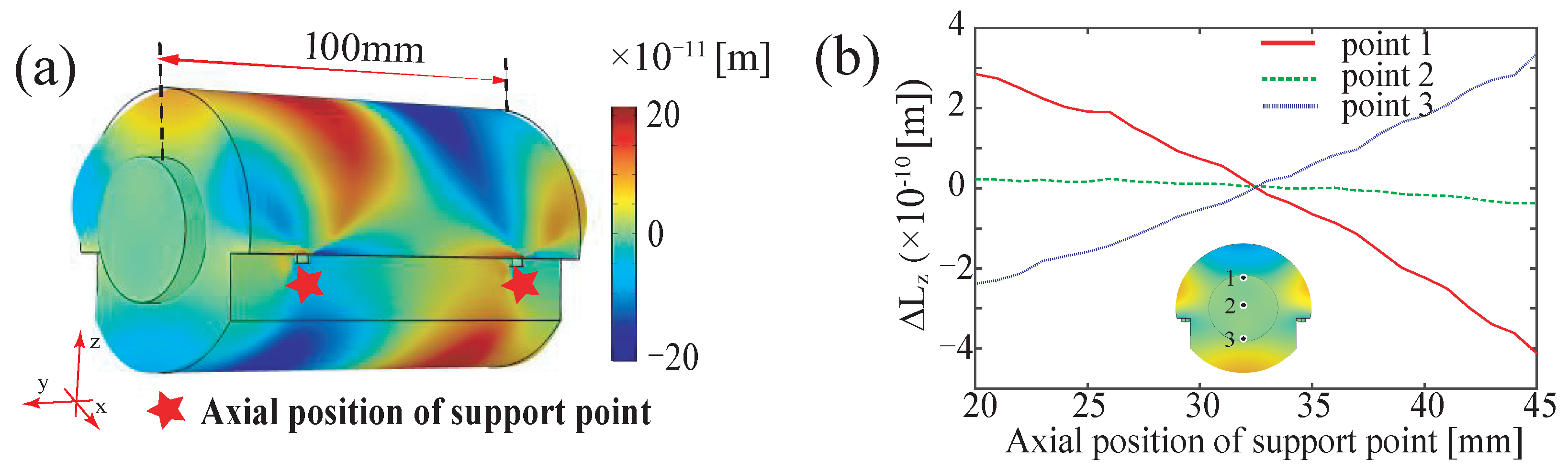
30] is improved by the cylindrical cavity. The notched structure can provide stable support and restrict rotation, with the force direction not along the radial direction. Furthermore, its low processing cost makes it the most commonly used structure at present. To achieve vibration insensitivity in the horizontal plane, a four-point symmetrical mounting is employed and implemented with two pairs of 3.2 mm diameter Teflon spheres. We further searched for the optical support points through finite-element analysis of cavity deformation with 14,950 mesh elements. Considering the axial symmetry, we numerically simulated the axial displacements for the three points at the end of the cavity marked in the insert of
Figure 2b by varying the axial position of the support points with a step length of 1 mm.
Figure 2a shows a representation of the solution at y = 32.5 mm, where values of
and 0.17 for the Young’s modulus and Poisson’s ratio are used for both the mirror and spacer, which are made of ULE glass.
Figure 2b gives the axial displacement as a function of the support point location. It is found that the minimum displacement at the three points is achieved at y = 32.5 mm, and the axial displacement at the mirror surface is also minimized. We therefore chose this location as the support point to minimize the cavity deformation when loaded.
3. System Tests and Results
The lasers of the two wavelengths were locked onto a set of ultra-stable cavities simultaneously. Therefore, a pair of dichroic mirrors (DMLP950T, Thorlabs, Newton, NJ, USA) was used to couple the lasers, and the modulation frequencies were set to 10 MHz and 12 MHz, respectively, so as to avoid disturbance between the two locking systems.
We used this high-finesse cavity as the optical reference to perform sideband Pound–Drever–Hall (PDH) locking [
15,
31] and thus stabilize the laser frequency. As shown in
Figure 3, the output of a tunable single-frequency diode laser (DL Pro, Toptica, Germany) passes through a fiber-coupled EOM (bandwidth 10 GHz) following the optical-power-splitting elements. The phase-modulated light transmits through a polarizing beam splitter (PBS) and passes through a quarter-wave plate (QWP), then is directed into the cavity. The reflected light passes through the QWP and PBS and is collected by the photodiode. The cavity transmission is split into two parts for monitoring the coupling mode and the locking status. The photodiode outputs of both reflection and transmission are induced to the PreciLock for producing the error signal. The produced signal is fed into the piezoceramic (PZT) and diode currents of the laser. The control signal of the EOM consists of two parts: the carrier signal provided by the synthHD (V2) and the modulation signal provided by the Precilock. After the two signals are combined by a power splitter (ZFRSC-42-S+, mini-circuit), they respectively provide the sideband frequency and the modulation frequency. This sideband locking is implemented to provide wide-range tunability of the laser frequency.
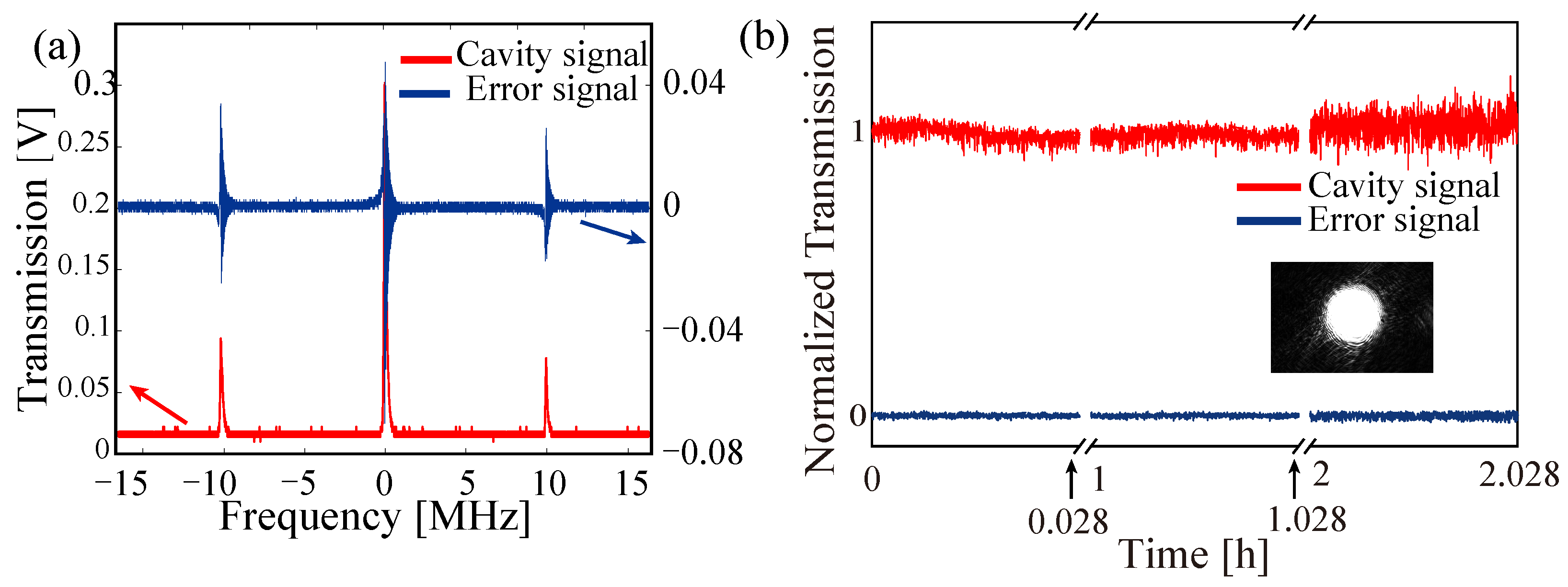
Figure 4a,b illustrate the transmission and error signals at the scanning and locking modes. After this system was set up in the laboratory environment, it was transported over 400 km away. During the transportation, it experienced situations like being carried by car and train, being dragged, and getting bumped. After the system was delivered, it only required minor adjustments to resume operation. However, the system test was not conducted while the system was in motion. Instead, it was tested in a very noisy environment. The system was placed on the eighth floor, and during the test, there were noises such as people talking, walking, and the sound of a fan. During the 2 h monitoring period, the system maintained its locking status, as shown in
Figure 4b.
We proceed to characterize the optical cavity in terms of cavity FSR and finesses. To obtain the FSR, we linearly scanned the laser frequency over two adjacent cavity fundamental modes (TEM00 mode). By tuning the modulation frequency, the +1st order sideband resonance of the high-frequency fundamental mode could overlap with the −1st order sideband signal of the lower-frequency one. We thus found that the FSR was twice the modulation frequency. Experimentally, the FSR was determined as 1.495849 GHz, corresponding to a cavity length of 10.02775 cm.
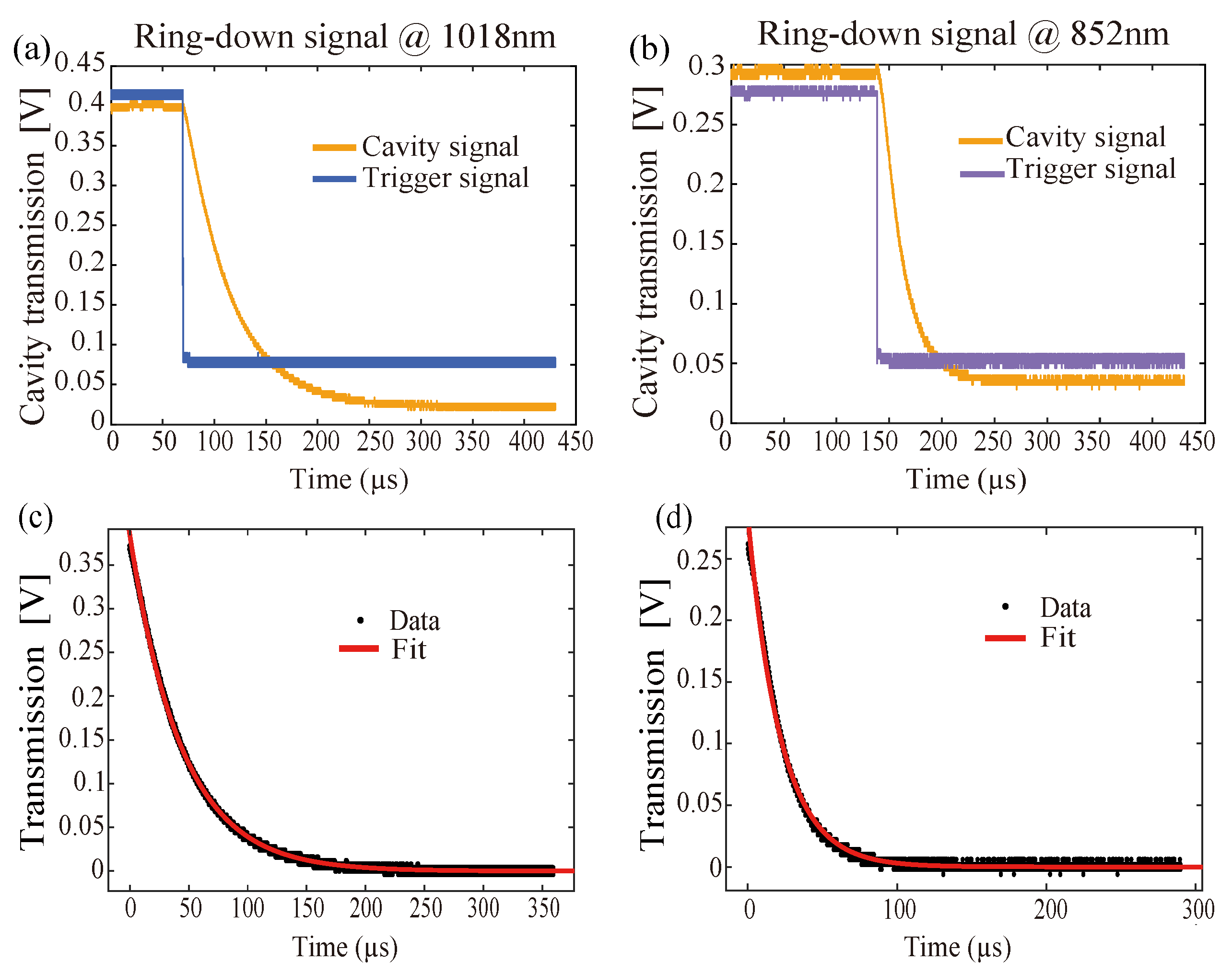
A cavity ring-down measurement was performed to determine the cavity finesses. The laser was initially locked to the optical reference cavity. The fiber-coupled EOM driving frequency was instantaneously turned off, and the cavity transmission at 1018 nm and 852 nm thus underwent exponential decay, as shown in
Figure 5a,b, respectively. The exponential fit gave a
decay time
of 43.8447 ± 0.1997 μs at 1018 nm and 21.8088 ± 0.3107 μs at 852 nm. Finally, the fitting formula
determined the finesses of 412,081 ± 1877 at 1018 nm and 20,4971 ± 2918 at 852 nm.
For external field measurements, the primary concern is narrowing the laser linewidth, which can be effectively achieved by a high-Q cavity design. However, two additional critical challenges arise: First, ULE cavity drift must be managed during transit or shortly after relocation. Key drift-inducing factors include heat conduction and gradual cavity creep. Second, while transportability necessitates securing the cavity with multiple limit screws to minimize displacement between the optical light path and cavity, this mechanical rigidity creates a tradeoff: deformations in the vacuum structure, due to external environmental changes, inevitably impose stress on the cavity, inducing ULE cavity distortion. In addition, in noisy environments, over-rigid fixation exacerbates noise transmission, as mechanical perturbations couple more directly with the cavity. Balancing these constraints during system assembly requires careful engineering.
Notably, Doppler broadening of thermal atomic systems offers partial tolerance for residual drift in microwave electric field measurements, but full optimization remains essential. A promising solution involves integrating the optical path system with the ULE cavity. Such integration would eliminate the need for mechanical constraints to restrict relative displacement. However, this remains a technical challenge at present. In this case, we only need to focus on the phase noise caused by temperature and vibration, as well as the servo noise caused by the locking loop, etc., which will greatly reduce the difficulty of system design.
4. Conclusions and Perspectives
Through elaborate mechanical design and wide-range tunable sideband Pound–Drever–Hall (PDH) locking, we have developed a transportable ultra-stable laser system for two-photon Rydberg excitation applications, like microwave electric field sensors. We characterized the optical reference cavity, and the cavity ring-down measurement results showed dual-wavelength finesses of 412,081 ± 1877 (at 1018 nm) and 204,971 ± 2918 (at 852 nm). By incorporating an auto-relock unit and an active vibration isolation unit, the system can operate continuously for over 2 h, which makes long-term operation at various measurement sites possible. Future research will focus on upgrading cavity structure, characterizing the long-term instability or drift of the system, further reducing the intensity of noise, servo noise, etc., and exploring the system’s practical applications.
Author Contributions
Software, C.Z.; validation, C.Z. and Z.X.; investigation, Z.X.; data curation, Z.X.; writing—original draft preparation, Z.X. and D.L.; writing—review and editing, D.L.; supervision, Z.X. and D.L.; project administration, Z.X.; funding acquisition, Z.X. All authors have read and agreed to the published version of the manuscript.
Funding
This work is supported by National Key R&D Program of China under Grant No. 2020YFA0309400, NNSFC under Grant Nos. 2222409 and 12174081, 11974228, and the Key Research and Development Program of Shanxi Province (Grant No. 202101150101025).
Institutional Review Board Statement
Not applicable.
Informed Consent Statement
Not applicable.
Data Availability Statement
Data underlying the results presented in this paper are not publicly available at this time, but may be obtained from the authors upon reasonable request.
Acknowledgments
We would like to express our gratitude to Heng Shen, Long Tian, and Qingwei Wang for their discussions and guidance during the process of crystal selection and experimental design optimization. Additionally, we are thankful to all the efforts of students for their significant support in the cavity structure design, data measurement, and data analysis.
Conflicts of Interest
The authors declare no conflicts of interest. The funders had no role in the design of the study; in the collection, analyses, or interpretation of data; in the writing of the manuscript; or in the decision to publish the results.
References
- Šibalic, N.; Adams, C.S. Rydberg Physics; IOP Publishing: Bristol, UK, 2018. [Google Scholar]
- Zhang, C.; Pokorny, F.; Li, W.; Higgins, G.; Pöschl, A.; Lesanovsky, I.; Hennrich, M. Submicrosecond entangling gate between trapped ions via Rydberg interaction. Nature 2020, 580, 345–349. [Google Scholar] [CrossRef] [PubMed]
- Saffman, M.; Walker, T.G.; Mølmer, K. Quantum information with Rydberg atoms. Rev. Mod. Phys. 2010, 82, 2313–2363. [Google Scholar] [CrossRef]
- Jing, M.; Hu, Y.; Ma, J.; Zhang, H.; Zhang, L.; Xiao, L.; Jia, S. Atomic superheterodyne receiver based on microwave-dressed Rydberg spectroscopy. Nat. Phys. 2020, 16, 911–915. [Google Scholar] [CrossRef]
- Ding, D.S.; Liu, Z.K.; Shi, B.S.; Guo, G.C.; Mølmer, K.; Adams, C.S. Enhanced metrology at the critical point of a many-body Rydberg atomic system. Nat. Phys. 2022, 18, 1447–1452. [Google Scholar] [CrossRef]
- Liu, X.H.; Liao, K.Y.; Zhang, Z.X.; Tu, H.T.; Bian, W.; Li, Z.Q.; Zheng, S.Y.; Li, H.H.; Huang, W.; Yan, H.; et al. Continuous-Frequency Microwave Heterodyne Detection in an Atomic Vapor Cell. Phys. Rev. Appl. 2022, 18, 054003. [Google Scholar] [CrossRef]
- Holloway, C.L.; Gordon, J.A.; Jefferts, S.; Schwarzkopf, A.; Anderson, D.A.; Miller, S.A.; Thaicharoen, N.; Raithel, G. Broadband Rydberg Atom-Based Electric-Field Probe for SI-Traceable, Self-Calibrated Measurements. IEEE Trans. Antennas Propag. 2014, 62, 6169–6182. [Google Scholar] [CrossRef]
- Shi, S.; Xu, B.; Zhang, K.; Ye, G.S.; Xiang, D.S.; Liu, Y.; Wang, J.; Su, D.; Li, L. High-fidelity photonic quantum logic gate based on near-optimal Rydberg single-photon source. Nat. Commun. 2022, 13, 4454. [Google Scholar] [CrossRef]
- Petrosyan, D.; Mølmer, K. Deterministic Free-Space Source of Single Photons Using Rydberg Atoms. Phys. Rev. Lett. 2018, 121, 123605. [Google Scholar] [CrossRef]
- Bluvstein, D.; Levine, H.; Semeghini, G.; Wang, T.T.; Ebadi, S.; Kalinowski, M.; Keesling, A.; Maskara, N.; Pichler, H.; Greiner, M.; et al. A quantum processor based on coherent transport of entangled atom arrays. Nature 2022, 604, 451–456. [Google Scholar] [CrossRef]
- Bluvstein, D.; Evered, S.J.; Geim, A.A.; Li, S.H.; Zhou, H.; Manovitz, T.; Ebadi, S.; Cain, M.; Kalinowski, M.; Hangleiter, D.; et al. Logical quantum processor based on reconfigurable atom arrays. Nature 2024, 626, 58–65. [Google Scholar] [CrossRef]
- Ebadi, S.; Wang, T.T.; Levine, H.; Keesling, A.; Semeghini, G.; Omran, A.; Bluvstein, D.; Samajdar, R.; Pichler, H.; Ho, W.W.; et al. Quantum phases of matter on a 256-atom programmable quantum simulator. Nature 2021, 595, 227–232. [Google Scholar] [CrossRef] [PubMed]
- Evered, S.J.; Bluvstein, D.; Kalinowski, M.; Ebadi, S.; Manovitz, T.; Zhou, H.; Li, S.H.; Geim, A.A.; Wang, T.T.; Maskara, N.; et al. High-fidelity parallel entangling gates on a neutral-atom quantum computer. Nature 2023, 622, 268–272. [Google Scholar] [CrossRef] [PubMed]
- Liu, Y.; Sun, Y.; Fu, Z.; Xu, P.; Wang, X.; He, X.; Wang, J.; Zhan, M. Infidelity Induced by Ground-Rydberg Decoherence of the Control Qubit in a Two-Qubit Rydberg-Blockade Gate. Phys. Rev. Appl. 2021, 15, 054020. [Google Scholar] [CrossRef]
- Thorpe, J.I.; Numata, K.; Livas, J. Laser frequency stabilization and control through offset sideband locking to optical cavities. Opt. Express 2008, 16, 15980. [Google Scholar] [CrossRef]
- Matei, D.; Legero, T.; Häfner, S.; Grebing, C.; Weyrich, R.; Zhang, W.; Sonderhouse, L.; Robinson, J.; Ye, J.; Riehle, F.; et al. 1.5 µm Lasers with Sub-10 mHz Linewidth. Phys. Rev. Lett. 2017, 118, 263202. [Google Scholar] [CrossRef]
- Kessler, T.; Hagemann, C.; Grebing, C.; Legero, T.; Sterr, U.; Riehle, F.; Martin, M.J.; Chen, L.; Ye, J. A sub-40-mHz-linewidth laser based on a silicon single-crystal optical cavity. Nat. Photonics 2012, 6, 687–692. [Google Scholar] [CrossRef]
- Ludlow, A.D.; Zelevinsky, T.; Campbell, G.K.; Blatt, S.; Boyd, M.M.; De Miranda, M.H.G.; Martin, M.J.; Thomsen, J.W.; Foreman, S.M.; Ye, J.; et al. Sr Lattice Clock at 1 × 10⁻¹⁶ Fractional Uncertainty by Remote Optical Evaluation with a Ca Clock. Science 2008, 319, 1805–1808. [Google Scholar] [CrossRef]
- Rosenband, T.; Hume, D.B.; Schmidt, P.O.; Chou, C.W.; Brusch, A.; Lorini, L.; Oskay, W.H.; Drullinger, R.E.; Fortier, T.M.; Stalnaker, J.E.; et al. Frequency Ratio of Al+ and Hg+ Single-Ion Optical Clocks; Metrology at the 17th Decimal Place. Science 2008, 319, 1808–1812. [Google Scholar] [CrossRef]
- Waldman, S.J. Status of LIGO at the start of the fifth science run. Class. Quantum Gravity 2006, 23, S653–S660. [Google Scholar] [CrossRef]
- Millo, J.; Abgrall, M.; Lours, M.; English, E.M.L.; Jiang, H.; Guéna, J.; Clairon, A.; Tobar, M.E.; Bize, S.; Le Coq, Y.; et al. Ultralow noise microwave generation with fiber-based optical frequency comb and application to atomic fountain clock. Appl. Phys. Lett. 2009, 94, 141105. [Google Scholar] [CrossRef]
- Fortier, T.M.; Kirchner, M.S.; Quinlan, F.; Taylor, J.; Bergquist, J.C.; Rosenband, T.; Lemke, N.; Ludlow, A.; Jiang, Y.; Oates, C.W.; et al. Generation of ultrastable microwaves via optical frequency division. Nat. Photonics 2011, 5, 425–429. [Google Scholar] [CrossRef]
- Leibrandt, D.R.; Thorpe, M.J.; Notcutt, M.; Drullinger, R.E.; Rosenband, T.; Bergquist, J.C. Spherical reference cavities for frequency stabilization of lasers in non-laboratory environments. Opt. Express 2011, 19, 3471. [Google Scholar] [CrossRef]
- Webster, S.; Gill, P. Force-insensitive optical cavity. Opt. Lett. 2011, 36, 3572. [Google Scholar] [CrossRef] [PubMed]
- Chen, X.; Jiang, Y.; Li, B.; Yu, H.; Jiang, H.; Wang, T.; Yao, Y.; Ma, L. Laser frequency instability of 6 × 10⁻¹⁶ using 10-cm-long cavities on a cubic spacer. Chin. Opt. Lett. 2020, 18, 030201. [Google Scholar] [CrossRef]
- Argence, B.; Prevost, E.; Lévèque, T.; Le Goff, R.; Bize, S.; Lemonde, P.; Santarelli, G. Prototype of an ultra-stable optical cavity for space applications. Opt. Express 2012, 20, 25409. [Google Scholar] [CrossRef]
- Chen, Q.F.; Nevsky, A.; Cardace, M.; Schiller, S.; Legero, T.; Häfner, S.; Uhde, A.; Sterr, U. A compact, robust, and transportable ultra-stable laser with a fractional frequency instability of 1 × 10⁻¹⁵. Rev. Sci. Instrum. 2014, 85, 113107. [Google Scholar] [CrossRef]
- Boyd, J.A.; Lahaye, T. A basic introduction to ultrastable optical cavities for laser stabilization. Am. J. Phys. 2024, 92, 50–58. [Google Scholar] [CrossRef]
- Jin, L.; Jiang, Y.; Yao, Y.; Yu, H.; Bi, Z.; Ma, L. Laser frequency instability of 2 × 10⁻¹⁶ by stabilizing to 30-cm-long Fabry-Pérot cavities at 578 nm. Opt. Express 2018, 26, 18699–18707. [Google Scholar] [CrossRef]
- Wang, Z.; Ma, Z.; Wei, W.; Chang, J.; Zhang, J.; Wu, Q.; Yuan, W.; Deng, K.; Lu, Z.; Zhang, J. Noise characterization of an ultra-stable laser for optical clocks. Rev. Sci. Instrum. 2024, 95, 053002. [Google Scholar] [CrossRef]
- Black, E.D. An introduction to Pound–Drever–Hall laser frequency stabilization. Am. J. Phys. 2001, 69, 79–87. [Google Scholar] [CrossRef]
Figure 1.
Overall setup and design details. (a) The front view of the system. The cabinet is a standard 19-inch rack with a height of 1200 mm. This system includes two Toptica lasers and a Precilaser fiber amplifier, which occupy the upper 10U space. The middle 4U is reserved for the control system, and the lower 8U is for the ULE cavity. (b) A side view of the system, where the Windows tablet can be seen. (c) The upper part is the input-coupling optical path diagram. The inset is the merged polarization-selection optical path composed of the polarization beam splitter (PBS) and the wave plate (WP). The lower part is the output-coupling optical path diagram. HR: high-reflectivity mirror; DM: dichroic mirror; BS: beam splitter; CCD: camera. (d) Cavity installation and optical path diagram. The mode-matching optics and the monitor optics are fixed on the two ends of the vacuum chamber for shortening the light path and improving the stability. The vacuum is maintained by a 5 L/s ion pump. (e) Cavity housing design. The ULE cavity is installed within a two-layer shielding structure, which is then placed inside the vacuum chamber. Three Peltier elements are installed between the second shielding layer and the vacuum chamber for cavity temperature control. Both viewports for the optical path are 4-degrees-oblique-mounted to avoid multiple reflections between the cavity and viewport. (f) A diagram of the notched cavity support. At the position of the notch, a U-shaped frame is used for support, where the support design is adopted in the up–down direction, and the rotation limit design is applied in the horizontal direction. The limit design is also implemented in the front–back direction. In addition, in order to prevent displacement caused by overturning of the cavity during transportation, two pairs of screws are added in the radial direction approximately 60 degrees above. This ensures that the movement of the cavity is restricted in all directions.
![Photonics 12 00559 g001]()
Figure 2.
The solutions of the finite element analysis. (a) The color bar represents the corresponding deformation. Please note that the simulation result is timed for easy observation. The insert on the right is the axial view of the support position. (b) Deformation results for different support positions. The optimal supporting position is 32.5 mm away from the center of the cavity. The insert shows the three chosen points for deformation analysis. Point 2 is at the cavity axis, while point 1 and point 3 are 12.7 mm away from the cavity axis.
Figure 3.
Locking scheme. The system is locked using the PDH method. A small amount of laser power is picked up by the PBS and then injected into the fiber-coupled EOM for modulating. Then, the modulated laser is injected into the cavity. The reflection light of the cavity is collected by a PD (photodetector, PDA36-A2, Thorlabs, Newton, NJ, USA). The transmitted light is divided into two parts for monitoring the coupling mode (by CCD) and the locking status (by PD, PDA36-A2, Thorlabs, Newton, NJ, USA, respectively. The SynthHD (V2) is used to produce the carrier frequency, which is mixed with the modulation signal for sideband locking. The Preci-Lock controller can produce the modulation signal, perform the demodulation, realize the PID servo, and realize the auto-relock. The fast and slow feedback signals are sent back to current and PZT, respectively. The monitor, frequency produced, and locking are all controlled by a tablet PC.
Figure 4.
(a) Transmitted signal (red line) and error signal (blue line). (b) Transmitted signal and error signal when laser is locked for 2 h; insert is transmitted TEM00 mode monitored by camera.
Figure 4.
(a) Transmitted signal (red line) and error signal (blue line). (b) Transmitted signal and error signal when laser is locked for 2 h; insert is transmitted TEM00 mode monitored by camera.
Figure 5.
Cavity ring-down measurement. The blue line in (a,b) is the trigger signal, while the yellow line is the ring-down signal measured by the transmitted PD. The corresponding ring-down signal and fitting curve are shown in (c,d).
Figure 5.
Cavity ring-down measurement. The blue line in (a,b) is the trigger signal, while the yellow line is the ring-down signal measured by the transmitted PD. The corresponding ring-down signal and fitting curve are shown in (c,d).
| Disclaimer/Publisher’s Note: The statements, opinions and data contained in all publications are solely those of the individual author(s) and contributor(s) and not of MDPI and/or the editor(s). MDPI and/or the editor(s) disclaim responsibility for any injury to people or property resulting from any ideas, methods, instructions or products referred to in the content. |
© 2025 by the authors. Licensee MDPI, Basel, Switzerland. This article is an open access article distributed under the terms and conditions of the Creative Commons Attribution (CC BY) license (https://creativecommons.org/licenses/by/4.0/).

