Article

MgO-Based Fabry-Perot Vibration Sensor with a Fiber-Optic Collimator for High-Temperature Environments

State Key Laboratory of Widegap Semiconductor Optoelectronic Materials and Technologies, North University of China, Taiyuan 030051, China
*
Author to whom correspondence should be addressed.
Photonics 2025, 12(6), 524; https://doi.org/10.3390/photonics12060524
Submission received: 6 April 2025 / Revised: 7 May 2025 / Accepted: 21 May 2025 / Published: 22 May 2025
(This article belongs to the Special Issue Emerging Trends in Fiber Optic Sensing)

Abstract

:
In this paper, a MgO-based high-temperature Fabry-Perot (F-P) vibration sensor with a fiber-optic collimator is proposed and experimentally demonstrated at 1000 °C. The sensor is composed of a sensing unit and a fiber-optic collimator. The F-P cavity is formed by the upper surface of the inertial mass block and the countersunk hole of the cover layer. The length of the F-P cavity changes with external vibrations. The sensing unit is prepared by wet etching technology and three-layer direct bonding technology, which ensure its stability and reliability in high-temperature environments. The experimental results indicate that the sensor can operate stably within a range from room temperature up to 1000 °C. The sensitivity and non-linearity of the sensor at 1000 °C are 1.3224 nm/g and 3.8%, respectively. Furthermore, the sensor operates at frequencies of up to 4 kHz while remaining unaffected by lateral vibration signals. The high-temperature F-P vibration sensor can effectively deal with the fiber damage in extreme environments and exhibits considerable potential for widespread applications.

1. Introduction

High temperature vibration sensors play an important role in vibration monitoring under extreme environmental conditions, such as ground thermal vibration testing of hypersonic vehicle structures and aerospace engine health monitoring [1,2,3,4]. High-temperature vibration sensors are comprised primarily of two categories: electrical sensors and fiber-optic sensors. Electrical sensors can only operate at temperatures not exceeding 800 °C and are vulnerable to electromagnetic interference [5,6,7,8]. In contrast, fiber-optic sensors have attracted significant interest owing to their robust anti-interference capabilities, high sensitivity, high temperature resistance, and distributed monitoring [9,10,11,12].
In terms of demodulation methods, fiber-optic vibration sensors mainly include intensity demodulation, wavelength demodulation, and phase demodulation. Intensity demodulation is susceptible to light source variations and transmission losses [13,14]. Wavelength demodulation is affected by temperature changes and has a limited response speed [15,16]. In comparison, phase demodulation provides notable benefits in both precision and sensitivity [17,18]. In principle, common phase vibration sensors include Fabry-Perot interferometer, Mach–Zehnder interferometer, and Michelson interferometer. Among them, the F-P interferometer is extensively used owing to its uncomplicated structure, high sensitivity and fast dynamic response [19,20]. Huang et al. used sapphire optical fibers and 6H-SiC to fabricate a sensor, and the sensing unit was processed by the femtosecond laser. The non-linearity of the sensor is 4.96% at 800 °C [21]. Mahissi et al. prepared a four-cantilever-beam structure with a sensitivity of 370 mV/g and a resonant frequency of 3750 Hz using the silicon carbide. The sensor can operate stably at 20–800 °C [22]. Cui et al. prepared a sensor with a double cantilever beam structure. The sensor was achieved by femtosecond laser etching of the sapphire wafer. With a sensitivity of 20.91 nm/g and a resonance frequency of 2700 Hz, the sensor can operate up to 1500 °C [23]. According to the above examples, sensors use either ordinary quartz optical fibers or sapphire optical fibers for signal transmission. However, due to the effects of increased transmission loss and decreased mechanical strength of quartz optical fibers in high-temperature environments, it is difficult for the sensors to work over a long time. Sapphire optical fiber has excellent high-temperature resistance, but the complex transmission mode makes the demodulation process more complicated at the same time. In previous research, we proposed a silicon-based vibration sensor that could operate stably at 400 °C [24]. To further improve the operating temperature of the sensor, we have optimized the material selection and the sensor preparation process, increasing the working temperature to 800 °C [25] and 1000 °C [26], respectively. However, the problem of fiber damage caused by heat transfer is still not solved.
A MgO high-temperature F-P vibration sensor with a fiber-optic collimator is proposed in this paper. Between the inertial mass and the countersunk hole in the cover layer is the F-P cavity. A direct bonding method and wet chemical etching are employed to fabricate the sensing unit, making it suitable for mass production. The sensing unit adopts a four-cantilever beam structure, which enhances its stability in a noisy environment. A collimating lens is used to send and receive the vibration signal in high temperatures areas, effectively preventing the breakage and damage of optical fiber in such environments. The sensor is demodulated using a three-wavelength demodulation method to avoid the effects of fiber optic transmission losses. Finally, the sensor is tested at different temperatures to validate its performance.

2. Operating Principle

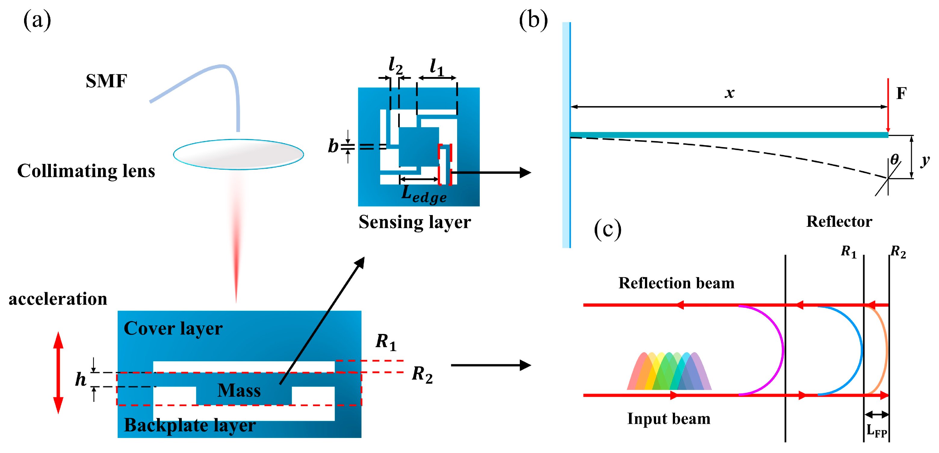
2.1. Mechanical Principle of the Sensor

Figure 1a shows the structure of the sensor. It is mainly composed of a sensing unit and a fiber-optic collimator. The first layer has a countersunk hole that collectively forms a F-P cavity with the inertial mass. The second layer, referred to as the sensing layer, is composed of a four-cantilever-beam structure integrated with an inertial mass. The third layer (backplane layer) is processed through computer numerical control (CNC) technology to form a recessed hole.
When an external excitation is applied, the cantilever beam undergoes bending deformation. The maximum bending displacement, numerically equivalent to the inertial mass movement, occurs at the cantilever’s free end. The force diagram of the beam is shown in Figure 1b. According to the fundamentals of material mechanics and the curvature radius equation,
1 ρ x = M x E I ,
1 ρ x = y x 1 + y x 3 2 2 ,
where ρ(x) is the radius of curvature of the neutral layer of the cantilever beam during bending, M(x) is the bending moment along the beam, y(x) describes its deflection profile, E denotes the Young’s modulus of MgO, and I corresponds to the moment of inertia of the cantilever beam’s cross-section. The sensitivity of the sensor corresponds to the maximum bending displacement of the beam under an acceleration of 1 g. It can be expressed as
S = m g 24 l 1 3 + m g 8 l 1 2 l 2 + m g 12 l 2 3 / E b h 3 12 ,
where m denotes the mass of the inertial mass block, g is the gravitational acceleration, l 1 and l 2 represent the lengths of the individual cantilever beams, b is their width, and h is their thickness. The structural parameters of the sensing unit prepared in this paper are shown in Table 1. And the resonant frequency f of the sensing unit is calculated using the formula as follows [21]:
f = 1 2 π K m = 1 2 π g S .
According to the calculation results, the resonance frequency of the sensor is 15.829 kHz, indicating that it has a wide frequency response bandwidth and great frequency stability in practical applications.
The acceleration a can be measured through the variation in cavity length L F P of the F-P cavity. Therefore, as long as the variation in cavity length L F P is accurately obtained, the acceleration signal can be effectively demodulated. The relationship between them is
a = g S · L F P .

2.2. Demodulation Principle of the Sensor

Figure 1c shows the F-P cavity interference diagram. The light propagates orthogonally to the top surface of the inertial mass block and enters the F-P cavity via a collimating lens, thereby forming interference, which is expressed as
I r = I 1 + I 2 + 2 I 1 I 2 cos θ ,
where I r represents the intensity of the reflected light. I 1 and I 2 represent the reflected light intensities from the reflective surfaces R 1 and R 2 , respectively. θ = 4 π n L F P / λ is the interference phase between the reflected light. L F P is the length of the F-P cavity, n is the refractive index, and λ is the wavelength of the incident light.
From the sensor structure, it can be seen that the effective interference phenomenon only occurs in the shortest F-P cavity. Through the principle of low-coherence interference, a light source with a certain bandwidth only produces interference within its coherence length. Therefore, as long as the appropriate coherent length of the interference light is selected, interference can only occur in the shortest F-P cavity of the sensor, avoiding the influence of long cavities on signal demodulation [27]. The resulting phase shift can then be obtained through three-wavelength dynamic demodulation technique [28].
Variations in acceleration cause a relative shift between the inertial mass and the reflective surface R 1 , resulting in a change in the F-P cavity length and thereby modulating the interference signal phase. Accurate measurement of acceleration is achieved through phase demodulation. The relationship between the interference signal phase shift θ and the change in cavity length L F P is expressed as follows:
θ = 4 π n λ L F P ,
where the variation in L F P is numerically equivalent to the displacement of the inertial mass block along the axial direction and n represents the refractive index.
Finally, combining Equations (5) and (7), a relationship can be established between the measured acceleration a and the phase change Δ θ of the interference signal:
a = g λ 4 π n S Δ θ .

2.3. Principle of the Collimating Lens

The light emitted by the single-mode optical fiber can be thought of as a Gaussian beam. The Gaussian beam radius follows the same propagation and transformation laws as the spherical beam radius. The law is usually described by the ABCD matrix [29]:
q 2 = A q 1 + B C q 1 + D ,
where q 1 and q 2 denote the complex curvature radii at the input and output planes of the optical system, respectively, while A, B, C, and D represent the components of the corresponding transfer matrix.
When light is emitted from an optical fiber, it propagates in a divergent manner and enters the collimating lens. Due to its precise design, the collimating lens effectively compensates for the divergence angle of the incident light through its curvature and refractive index, thereby achieving collimated light output. As a result, the light emitted from the optical fiber is refracted by the lens surface and gradually adjusted to form a beam that is nearly parallel.
The fiber-optic collimator has a temperature limit of approximately 200 °C. To ensure its reliable operation under working conditions, finite element simulation is used to perform a thermal analysis of the sensor package, which is shown in Figure 2. Considering the sensor dimensions and thermal distribution of the fiber-optic collimator, the distance between the sensing unit and the collimator is set to 100 mm, at which point the temperature at the position of the collimator is about 150 °C.

3. Sensor Preparation

The preparation process of the sensor, which is illustrated in Figure 3, involves wet etching of the MgO wafer, direct bonding of MgO wafers, and incorporation of the fiber-optic collimator with the sensing unit.
During the preparation of the sensor, the first and second layers were processed using a wet etching process to form a sinkhole structure and a beam-mass block structure, respectively. During the wet etching process, the etching depth of the sinkholes was measured. The results show that the etching deviation across different locations is within 20 nm. The sensing unit is designed with central symmetry to ensure optimal structural stability, and the lower surface of the quality block is roughened to reduce interference. The third layer, which does not participate in the construction of the F-P cavity, is processed using CNC technology to form sinkholes, thereby reserving the space required for the displacement of the sensing layer. The detailed description of the wet chemical etching process and the three-layer direct bonding technology could be found in our previous research [26]. Phosphoric acid (H3PO4) is used as the etchant to ensure an optimal etching rate of the MgO wafer while reducing the surface roughness after etching. To reduce the thermal stress resulting from differences in thermal expansion between different materials, and to enhance the thermo-mechanical stability of the sensing unit in high-temperature environments, MgO wafers are bonded using direct bonding technology. The fiber-optic collimator is connected to the sensor package via a threaded connection, which avoids the use of adhesives in high-temperature environments and thereby ensures the high temperature stability of the sensor package. The encapsulation material is made of low-thermal-conductivity alumina ceramic, which can reduce the temperature at the position of the fiber-optic collimator and further ensure its proper working. Figure 3b shows the physical diagram of the sensor.

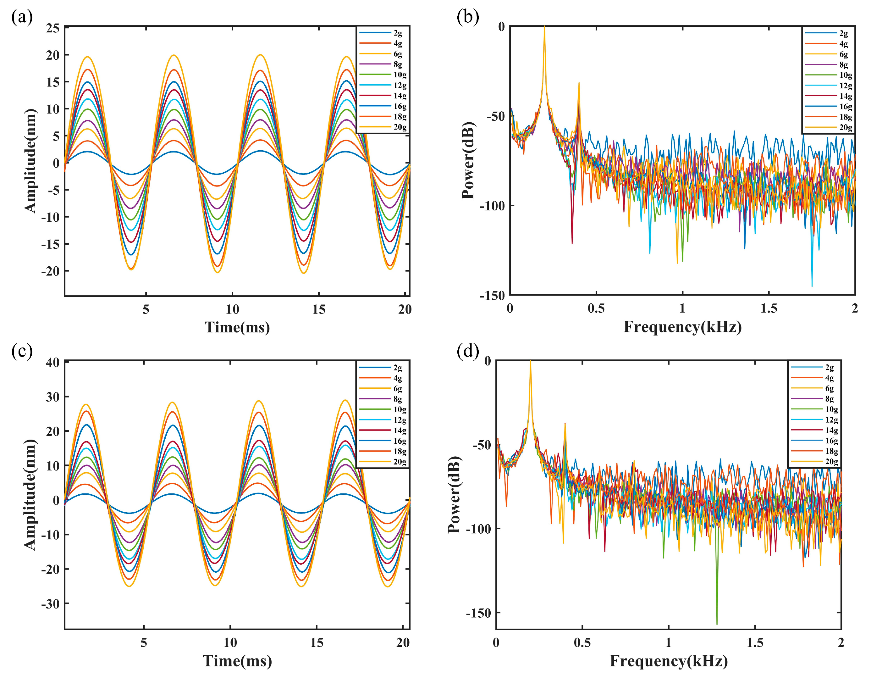
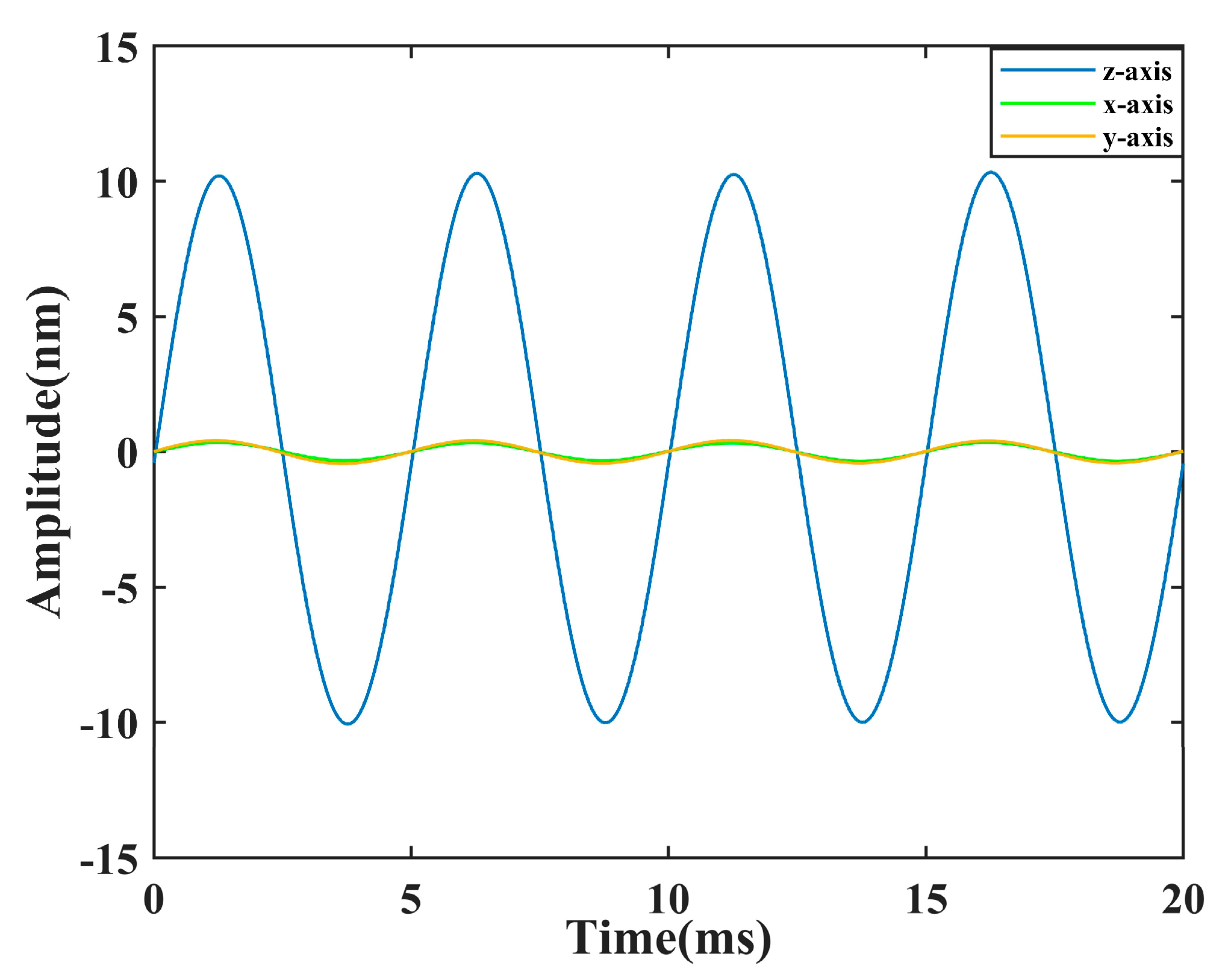
4. Experiments and Analysis

To evaluate the performance of sensors in high-temperature environments, a combined high-temperature and vibration testing system was established, as shown in Figure 4. The system mainly consists of a vibration excitation module, a high-temperature heating unit, an acceleration detection module, and a signal demodulation unit. The vibration excitation module uses an electromagnetic exciter in conjunction with a signal source and power amplifier to provide controllable vibration input. The high-temperature heating unit uses a split-type heating furnace with temperature sensors installed inside the furnace chamber to enable real-time temperature monitoring and closed-loop control. The sensor to be measured is rigidly connected to the exciter via a high-temperature-resistant metal rod to ensure effective transmission of the vibration signal. At the same time, a standard accelerometer is installed near the metal rods for vibration amplitude calibration. In terms of the demodulation method, we adopt the previously developed three-wavelength demodulation system to collect and process the signals of the sensor during operation [28]. The light source delivers optical signals to the sensor through a single-mode fiber and a coupler. After reflected back from the sensor, the light is divided into three different wavelength channels by the wavelength division multiplexer. The light signal with the central wavelength is then converted into an electrical signal by the photodiode. Finally, the analog-to-digital conversion system collects the voltage signals and transmits them to the computer for demodulation. Figure 5 shows the three-channel interference output signal of the sensor and the spectrum of the sensor. As can be seen from Figure 5b, the cavity length of the sensor is 42.812 μ m .
As the minimum setting temperature of the heating furnace is 600 °C, the high-temperature sensor was tested at 20 °C, 600 °C, 800 °C, and 1000 °C. The performance of the sensor is assessed through a stepwise elevation of the temperature. During the heating process, the excitation system applies vibrations at a fixed frequency (200 Hz) and the excitation acceleration increases linearly from 2 g to 20 g. After stabilization at each temperature stage, the interference signal output from the sensor is recorded. Subsequently, the signal is subjected to low-pass filtering and spectral analysis. By comparing the changes in amplitude-frequency response at different temperatures, parameters such as the sensitivity and the linear error are obtained. Figure 6a,c present the sensor’s time-domain responses at room temperature and at 1000 °C, respectively. Figure 6b,d display the frequency spectra of the temporal signals shown above after performing a fast Fourier transform (FFT). The results demonstrate that the sensitivity is 0.9971 nm/g at room temperature and 1.3224 nm/g at 1000 °C, with corresponding non-linearity errors of 1.5% and 3.8%, respectively. Figure 7 shows the output characteristics of the sensor at various temperatures and the variation in the sensitivity with temperature. It is observed that the sensitivity increases with rising temperature. The decrease in Young’s modulus of the MgO material at high temperature is the main reason for this phenomenon, which results in a reduction in structural stiffness, thereby enhancing the deformation response of the sensor and improving its sensitivity.
To further evaluate the dynamic response of the sensor, we performed a frequency response test on it. The test was conducted at a constant acceleration of 20 g, with the excitation frequency varied from 200 Hz to 4000 Hz in 200 Hz increments. Figure 8 shows the change in the length of the F-P cavity. It can be seen that the sensor is stable at each frequency point and has no significant amplitude fluctuations, indicating that the resonant frequency of the sensor is significantly greater than 4000 Hz. Therefore, the sensor is capable of reliable operation over a frequency range of 200–4000 Hz, exhibiting minimal fluctuations.
The sensor was tested along the X, Y, and Z axes to evaluate its cross-axis sensitivity. During the experiment, the installation angle of the sensor was adjusted so that the exciter applied a constant acceleration of 10 g to the sensor along different axes. Figure 9 shows the sensor responses in three directions. The experimental data indicate that the sensor output along the Z-axis is notably greater than that along the X- and Y-axes, indicating its excellent axial selectivity and low cross-axis sensitivity. It can be considered that the sensor is not affected by lateral vibration signals.
A performance comparison between the vibration sensor proposed in this paper and several existing F-P vibration sensors is summarized in Table 2. Compared with existing sensors, the sensor uses a collimating lens for light transmission. By placing the lens away from high-temperature areas, the impact on the quartz optical fiber can be reduced, thereby improving the operating temperature of the sensor. At the same time, the use of sapphire fibers has been avoided, which reduces the demands on the demodulation system. The sensor is packaged using a mechanical coupling method instead of adhesive bonding or laser welding, eliminating the influence of high-temperature-induced stress on the F-P cavity length and preventing the thermal damage to the optical fiber during the welding process. This approach significantly enhances the sensor’s stability under high-temperature conditions.

5. Conclusions

A MgO-based high-temperature F-P vibration sensor with a fiber-optic collimator is proposed in this paper. The sensing unit was fabricated using wet chemical etching and three-layer direct bonding techniques. The sensitivity of the sensing unit is theoretically calculated to be 0.9917 nm/g, with a resonance frequency of 15.829 kHz. Experimental measurements at room temperature revealed a sensitivity of 0.9971 nm/g, accompanied by a non-linearity of 1.5%. At 1000 °C, the sensitivity increases to 1.3224 nm/g, and the non-linearity is 3.8%. Frequency response testing confirms that the sensor maintains stable operation up to 4 kHz. Moreover, the sensor shows excellent resistance to lateral vibration disturbances. With its compatibility for mass production and reliable performance under high-temperature conditions, the sensor offers broad application prospects in high-temperature vibration measurement fields.

Author Contributions

Conceptualization, J.T.; methodology, P.J.; software, J.T.; validation, J.T., Q.Z., J.H. and Y.H.; writing—original draft preparation, J.T.; writing—review and editing, J.T., J.L., and H.W.; project administration, P.J. All authors have read and agreed to the published version of the manuscript.

Funding

This research was funded by the National Natural Science Foundation of China (grant number 52075505); the National Science and Technology Major Project of China (grant J2019-V-0015-0110); and the special fund for Science and Technology Innovation Teams of Shanxi Province (grant number 202204051001016).

Institutional Review Board Statement

Not applicable.

Informed Consent Statement

Not applicable.

Data Availability Statement

The data will be made available upon request.

Conflicts of Interest

The authors declare no conflicts of interest.

References

  1. Mills, A.R.; Kadirkamanathan, V. Sensing for aerospace combustor health monitoring. Aircr. Eng. Aerosp. Technol. 2020, 92, 37–46. [Google Scholar] [CrossRef]
  2. Wu, D.; Lin, L.; Ren, H. Thermal/Vibration Joint Experimental Investigation on Lightweight Ceramic Insulating Material for Hypersonic Vehicles in Extremely High-Temperature Environment up to 1500 °C. Ceram. Int. 2020, 46, 14439–14447. [Google Scholar] [CrossRef]
  3. Zeng, Q.; Chen, X. Combustor Technology of High Temperature Rise for Aero Engine. Progress. Aerosp. Sci. 2023, 140, 100927. [Google Scholar] [CrossRef]
  4. Kummitha, O.R.; Suneetha, L.; Pandey, K.M. Numerical Analysis of Scramjet Combustor with Innovative Strut and Fuel Injection Techniques. Int. J. Hydrogen Energy 2017, 42, 10524–10535. [Google Scholar] [CrossRef]
  5. Jiang, C.; Liu, X.; Yu, F.; Zhang, S.; Fang, H.; Cheng, X.; Zhao, X. High-temperature Vibration Sensor Based on Ba2TiSi2O8 Piezoelectric Crystal with Ultra-Stable Sensing Performance up to 650 °C. IEEE Trans. Ind. Electron. 2021, 68, 12850–12859. [Google Scholar] [CrossRef]
  6. Kubasov, I.V.; Kislyuk, A.M.; Malinkovich, M.D.; Temirov, A.A.; Ksenich, S.V.; Kiselev, D.A.; Bykov, A.S.; Parkhomenko, Y.N. A Novel Vibration Sensor Based on Bidomain Lithium Niobate Crystal. Acta Phys. Pol. A 2018, 134, 106–108. [Google Scholar] [CrossRef]
  7. Nagmani, A.K.; Behera, B. A Review on High Temperature Piezoelectric Crystal La3Ga5SiO14 for Sensor Applications. IEEE Trans. Ultrason. Ferroelectr. Freq. Control 2022, 69, 918–931. [Google Scholar] [CrossRef]
  8. Ning, H.; Yan, H.; Reece, M.J. Piezoelectric Strontium Niobate and Calcium Niobate Ceramics with Super-High Curie Points. J. Am. Ceram. Soc. 2010, 93, 1409–1413. [Google Scholar] [CrossRef]
  9. Cao, S.; Bai, J.; Zheng, Y.; Chai, H.; Gao, X.; Xue, C. High-Temperature Fiber-Optic Vibration Sensor Based on an Atomic Frequency Standard. ACS Photonics 2024, 11, 3713–3721. [Google Scholar] [CrossRef]
  10. Feng, R.; Chu, Y.; Liu, Z.; Wang, X.; Tang, F. Study on High Temperature Resistant Packaging of Ultra High Temperature Fabry-Perot Optical Fiber Vibration Sensor. IEEE Sens. J. 2021, 21, 27045–27050. [Google Scholar] [CrossRef]
  11. Lin, C.; Wang, N.; Chen, J.; Yan, X.; Zhang, X.; Cai, Y. Study on Fiber Fabry-Perot Displacement Sensor for Vibration Monitoring of Fuel Pin. Microw. Opt. Technol. Lett. 2024, 66, 34007. [Google Scholar] [CrossRef]
  12. Sun, S.; Wu, Y.; Pang, K.; Xu, X.; Chen, R.; He, Z. A High-Precision 3-D Vibration Acceleration Sensor Based on FBGs. IEEE Sens. J. 2025, 25, 2321–2330. [Google Scholar] [CrossRef]
  13. Kishore, P.; Dinakar, D.; Srimannarayana, K.; Vengal Rao, P. Vibration Sensor Using 2 × 2 Fiber Optic Coupler. Opt. Eng. 2013, 52, 107104. [Google Scholar] [CrossRef]
  14. Kimura, M.; Toshima, K. Vibration Sensor Using Optical-Fiber Cantilever with Bulb-Lens. Sens. Actuators A Phys. 1998, 66, 178–183. [Google Scholar] [CrossRef]
  15. Zhou, W.; Dong, X.; Ni, K.; Chan, C.C.; Shum, P. Temperature Insensitive Accelerometer Based on a Strain-Chirped FBG. Sens. Actuators A Phys. 2010, 157, 15–18. [Google Scholar] [CrossRef]
  16. Basumallick, N.; Chatterjee, I.; Biswas, P.; Dasgupta, K.; Bandyopadhyay, S. Fiber Bragg Grating Accelerometer with Enhanced Sensitivity. Sens. Actuators A Phys. 2012, 173, 108–115. [Google Scholar] [CrossRef]
  17. Li, Y.; Wang, Y.; Xiao, L.; Bai, Q.; Liu, X.; Gao, Y.; Zhang, H.; Jin, B. Phase Demodulation Methods for Optical Fiber Vibration Sensing System: A Review. IEEE Sens. J. 2022, 22, 1842–1866. [Google Scholar] [CrossRef]
  18. Sun, Z.; Liu, K.; Jiang, J.; Xu, T.; Wang, S.; Guo, H.; Zhou, Z.; Xue, K.; Huang, Y.; Liu, T. Dynamic Phase Extraction in an Ameliorated Distributed Vibration Sensor Using a Highly Stable Homodyne Detection. IEEE Sens. J. 2021, 21, 27005–27014. [Google Scholar] [CrossRef]
  19. Liu, Q.; Peng, W. Fast Interrogation of Dynamic Low-Finesse Fabry-Perot Interferometers: A review. Microw. Opt. Technol. Lett. 2021, 63, 2279–2291. [Google Scholar] [CrossRef]
  20. Wang, D.; Wu, Y.; Song, Y.; Wang, Y.; Zhu, L. High Sensitivity Fiber Optic Acceleration Sensor Based on Fabry-Perot Interferometer. Opt. Fiber Technol. 2022, 72, 102989. [Google Scholar] [CrossRef]
  21. Huang, Y.; Tang, F.; Ma, D.; Liu, Z.; Wang, X. Design, Fabrication, Characterization, and Application of an Ultra-High Temperature 6H-SiC Sapphire Fiber Optic Vibration Sensor. IEEE Photonics J. 2019, 11, 6802512. [Google Scholar] [CrossRef]
  22. Mahissi, M.; Tong, X.L.; Zhang, C.; Deng, C.; Wei, J.; Chen, S. Study on the Vibration Performances for a High Temperature Fiber F-P Accelerometer. Opt. Fiber Technol. 2021, 62, 102471. [Google Scholar] [CrossRef]
  23. Cui, Y.; Jiang, Y.; Zhang, Y.; Feng, X.; Hu, J.; Jiang, L. Sapphire Optical Fiber High-Temperature Vibration Sensor. Opt. Express 2022, 30, 1056–1065. [Google Scholar] [CrossRef]
  24. Qian, J.; Jia, P.; Liu, H.; Ren, Q.; Liu, J.; Qin, L.; Xiong, J. A MEMS Fiber-Optic Fabry-Perot Vibration Sensor for High-Temperature Applications. IEEE Access 2022, 10, 42908–42951. [Google Scholar] [CrossRef]
  25. Liu, H.; Jia, P.; Su, C.; Zhao, A.; Liu, J.; Ren, Q.; Xiong, J. High-Temperature Fiber-Optic Fabry-Perot Vibration Sensor Based on Single-Crystal Sapphire. Sensors 2023, 23, 4952. [Google Scholar] [CrossRef]
  26. Su, C.; Jia, P.; Zhao, A.; Tu, J.; Liu, J.; Ren, Q.; Xiong, J. Temperature-Decoupled Single-Crystal MgO Fiber-Optic Fabry-Perot Vibration Sensor Based on MEMS Technology for Harsh Environments. Micromachines 2024, 15, 616. [Google Scholar] [CrossRef] [PubMed]
  27. Ren, Q.; Jia, P.; An, G.; Liu, J.; Fang, G.; Liu, W.; Xiong, J. Dual-Wavelength Demodulation Technique for Interrogating a Shortest Cavity in Multi-Cavity Fiber-Optic Fabry-Perot Sensors. Opt. Express 2021, 29, 32658. [Google Scholar] [CrossRef]
  28. Ren, Q.; Jia, P.; An, G.; Liu, J.; Liu, W.; Xiong, J. Self-Compensation Three-Wavelength Demodulation Method for the Large Phase Extraction of Extrinsic Fabry-Perot Interferometric Sensors. Opt. Lasers Eng. 2023, 164, 107535. [Google Scholar] [CrossRef]
  29. Mukhopadhyay, S.; Gangopadhyay, S.; Sarkar, S. Coupling of a Laser Diode to a Monomode Elliptic-Core Fiber via a Hyperbolic Microlens on the Fiber Tip: Efficiency Computation with the ABCD Matrix. Opt. Eng. 2007, 46, 025008. [Google Scholar]
Figure 1. (a) The structural schematic of the vibration sensor. (b) The schematic diagram of cantilever beam under load. (c) The interference model of the F-P cavity.
Photonics 12 00524 g001
Figure 2. Thermal analysis of the sensor package.
Photonics 12 00524 g002
Figure 3. (a) Process flow diagram of the wet chemical etching. (b) Physical diagram of the sensor.
Photonics 12 00524 g003
Figure 4. The composite test system of high-temperature vibration sensors.
Photonics 12 00524 g004
Figure 5. (a) Three-channel interference signal of the sensor at 20 g. (b) The sensor spectrum.
Photonics 12 00524 g005
Figure 6. (a) Time-domain response at room temperature. (b) Frequency response at room temperature. (c) Time-domain response at 1000 °C. (d) Frequency response at 1000 °C.
Photonics 12 00524 g006
Figure 7. (a) Sensor cavity length change with temperature. (b) Cross-sensitivity of the sensor to temperature.
Photonics 12 00524 g007
Figure 8. Sensor cavity length change at different frequencies.
Photonics 12 00524 g008
Figure 9. Time-domain waveforms in different directions.
Photonics 12 00524 g009
Table 1. Structure parameters of the sensitive unit.
ParametersSymbolValue (Unit)
Length of the beam l 1 3.3 (mm)
Length of the beam l 2 0.5 (mm)
Width of the beam b 0.3 (mm)
Thickness of the beam h 0.3 (mm)
Side length of inertial mass L e d g e 3 (mm)
Density of MgO ρ 3580 (kg· m 3 )
Young’s modulus of MgO E 300 (GPa)
Sensitivity S 0.9917 (nm· g 1 )
Frequence f 15.829 (kHz)
Table 2. Characteristics of several high-temperature F-P vibration sensors.
Signal Transmission Method (in High-Temperature Area)Packaging
Method
The Highest Working
Temperature (°C)
Sensitivity
[21]Sapphire optical fiberHigh-temperature glue120044.64 mv/g
[23]Sapphire optical fiberInorganic glue150020.91 nm/g
[24]Quartz optical fiberWelded by CO2 laser4002.48 nm/g
[25]Quartz optical fiberCeramic glue8000.876 nm/g
[26]Quartz optical fiberHigh-temperature glue10000.0073 rad/g
this workFiber-optic collimatorMechanical coupling10000.9971 nm/g
Disclaimer/Publisher’s Note: The statements, opinions and data contained in all publications are solely those of the individual author(s) and contributor(s) and not of MDPI and/or the editor(s). MDPI and/or the editor(s) disclaim responsibility for any injury to people or property resulting from any ideas, methods, instructions or products referred to in the content.

