Abstract
This study introduces an optimization design method for large-scale curvature-adjustable optical mirrors, innovatively integrating parametric modeling with the optimized layout of actuators, targeting the achievement of extensive curvature adjustability and high-precision surface correction for segmented mirrors. The optimization objective is based on the surface figure residual when the curvature radius of the segmented mirror is altered by 100 mm. Through the optimization of the number, arrangement, and thickness of reinforcement ribs of the actuators on the back of the segmented mirror, a parametric model of a segmented mirror with an edge-to-edge distance of 510 mm and a radius of curvature 9100 mm is developed. Simulation outcomes reveal that a 0–15 μm variation in the actuators results in a curvature radius change of 178.45 mm in the segmented mirror, with a highly linear correlation, achieving a radius of curvature reconfiguration of the primary mirror in the optical system from 9100 mm to 9000 mm, with a residual surface figure error of less than 10 nm. The experimental results indicate that within a 0–15 μm closed-loop stroke range, the curvature radius of the segmented mirror can be adjusted by 146.89 mm, fulfilling the design objective of a lightweight mirror with a significantly adjustable curvature radius. This research is anticipated to offer technical support and serve as a reference for the assembly, adjustment, and inspection of large-aperture segmented mirrors, as well as for the curvature radius variation in multiple segmented mirrors, thereby holding substantial practical value in engineering applications.
1. Introduction
In contrast to traditional heavy, passive, and monolithic primary mirrors, contemporary large-aperture telescopes require lightweight, active control, and segmented structural characteristics [1,2]. Due to the individual processing and inspection of each segment, variations in the curvature radius are inevitable and cannot be compensated by other optical elements [3,4]. Additionally, on-orbit optical systems experience dynamic wavefront aberrations that affect imaging quality, necessitating real-time active correction of disturbances and manufacturing errors to restore the distorted wavefront to the ideal state [5].
The James Webb Space Telescope (JWST), currently in operation, employs a curvature actuator located at the center of the segmented mirrors for the fine adjustment of the figure to achieve precise error correction for the entire system. However, the adjustment range is limited to ±10 mm [6], and the surface correction effect is only sufficient for infrared band observations. For segmented mirrors in the visible band, a larger adjustment range and higher precision are required for on-orbit reconstruction [7,8,9]. Japan’s 3.6 m geostationary orbit segmented telescope adjusts aberrations by incorporating a deformable mirror in the optical path; however, for 10 m class large-aperture segmented telescopes, a high-density distribution of surface actuators on the deformable mirror is required, which is challenging to implement in engineering [10,11,12]. The extremely large telescopes (ELTs) currently under design and construction are equipped with active optical systems, enabling diffraction-limited observations in the near-infrared and longer wavelength ranges. However, extending the application of adaptive optics (AO) technology to the visible spectrum remains a challenge [13]. The deformable mirror technology based on microelectromechanical systems (MEMSs) features a high actuator integration density, zero hysteresis, and sub-nanometer repeatability (with an average step size of less than 1 nm), which enables precise wavefront correction. However, due to its limited stroke, it is primarily suitable for correcting small-scale wavefront aberrations [14]. Based on the construction of the LAMOST telescope and research on active primary mirrors, China has conducted some research on the adjustment of segmented primary mirror curvature radii [15,16,17], but it is difficult to meet the high-precision correction requirements of space telescopes, and more in-depth research is needed for engineering application transformation.
As telescope apertures increase, traditional adjustment methods can no longer meet the high-precision wavefront aberration correction requirements [18,19]. Embedding surface actuators on the back of segmented mirrors not only achieves a lightweight design but also the high integration of active control, which is an important method to match the current high-precision curvature adjustment and surface correction needs. This paper adopts a parametric modeling method to study the design method of a large-scale curvature-adjustable optical mirror; the relevant parameters of the optical mirror are illustrated in Figure 1. By optimizing the physical parameters on the back of segmented mirrors through iterative optimization, a parametric model of a segmented mirror with a radius of curvature 9100 mm is established. From simulation and experimental perspectives, the design goal of a wide range of curvature radius adjustability is achieved, providing a larger adjustment range for the reconfiguration of large-aperture segmented optical systems, which has practical guidance value.

Figure 1.
Schematic diagram of the segmented mirror’s key parameters. (The key parameters of the segmented mirror are defined as follows: The six vertices of the segmented mirror are defined as “vertex”, the centers of the six edges of the segmented mirror are defined as “midpoint”, and the center of the mirror surface is defined as “center”. The radial ribs extending from the center to the midpoints are defined as “midpoint radial ribs”, totaling six. The radial ribs extending from the center to the vertices are defined as “vertex radial ribs”, also totaling six).
2. Parametric Modeling and Mathematical Description
2.1. Parametric Modeling Theory
By utilizing a given parametric function file which encompasses descriptions of segmented mirror geometry, actuator layout, mesh density, and other parameter information, the required finite-element model is created, and the surface shape diagram is calculated. Users can alter parameters to obtain the optimal design outcome, iterating towards the most favorable output surface shape. The essence of iteration lies in the computation of the influence function, which represents the mapping of the reflective mirror surface shape under the actuation of a single actuator. That is, given a set of displacements, the corresponding actuator commands can be obtained using the least-squares method to accomplish the control of the surface shape. The parametric modeling process is depicted in Figure 2.

Figure 2.
Flowchart of parametric modeling for segmented mirrors with an adjustable radius of curvature.
2.2. Piezoelectric Effect-Equivalent Thermal Simulation
The direct piezoelectric effect refers to the property of certain non-centrosymmetric crystalline materials that, when subjected to mechanical deformation along a specific direction, generate an electrical charge that is directly proportional to the strain. The converse piezoelectric effect refers to the property of certain non-centrosymmetric crystalline materials to exhibit mechanical strain in response to an applied external electric field. Common materials such as quartz crystals and piezoelectric ceramics possess piezoelectric properties. The mechanical and electrical physical quantities involved in the piezoelectric effect can be mathematically expressed as follows:
where in Ti represents a 6 × 1 vector of stress components, Dl is a 3 × 1 vector of electric displacement components, Sk is a 6 × 1 vector of strain components, and Ej is a 3 × 1 vector of electric field components. is a 6 × 6 matrix of elastic coefficients, elk is a 3 × 6 matrix of piezoelectric coupling coefficients, and εlj represents the dielectric permittivity tensor, with the first subscript indicating the direction of electric field displacement and the second subscript indicating the component direction of electric field intensity.
The piezoelectric effect not only interrelates mechanical and electrical quantities through elastic coefficients and dielectric constants but also facilitates the mutual conversion between force and electricity. The corresponding mathematical expression is as follows:
In the equation, dmn represents the 3 × 6 piezoelectric coupling matrix.
The generalized Hooke’s law considering thermal effects can be expressed as follows:
where αk is the 6 × 1 matrix of thermal expansion coefficients, and ∆Tt is the temperature difference. By combining Equations (1)–(4), we obtain the following:
From Equation (5), the equivalent relationship between piezoelectric strain and thermal strain can be derived. In simulations, we equate the expansion of piezoelectric ceramics due to a 1 °C temperature change to that caused by a 1 V voltage change. At this point in the analysis, we observe that
The elastic modulus of equivalent piezoelectric ceramics can be determined as follows:
In the aforementioned formula, Kc denotes the stiffness of the encapsulated actuator, Lc represents the length of the actuator, ΔL1 signifies the stroke or displacement of the actuator, and Vc represents the corresponding voltage value that is determined with the actuator stroke ΔL1 as a known quantity. Ec is the elastic modulus of the equivalent piezoelectric ceramic, CTEc stands for the coefficient of thermal expansion of the equivalent piezoelectric ceramic, and Ac is the cross-sectional area of the equivalent piezoelectric ceramic. Thus, the thermal variable parameters for simulating the piezoelectric effect have been determined.
2.3. Actuator-Integrated Layout
Based on the equivalent principle of the piezoelectric effect, the piezoelectric actuator is regarded as a pure force actuator and is embedded within the back of the mirror substrate material [20,21,22,23,24], creating an equivalent bimetallic layer effect, as detailed in Figure 3.
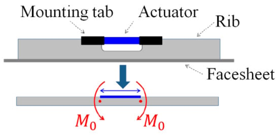
Figure 3.
Schematic representation of the equivalent bimetallic effect. (Red arrows indicate bending moments, red dots signify the effective beam ends of the simplified beam, blue arrows represent the actuator extension illustration, and blue lines indicate the actuator layout positions).
The control equation for the bending of a uniform cross-section beam is given as follows:
In the given equation, ρ represents the radius of curvature, M(x) denotes the bending moment, E is the modulus of elasticity, and I is the moment of inertia of the beam about its neutral axis. Under the assumption of small deformations, by applying calculus, the curvature 1/ρ at any point (x,y) (where the variable x denotes the horizontal interval range of the simply supported beam, and the variable y represents the vertical displacement deformation, with the left end of the simply supported beam serving as the reference origin) is expressed as follows:
Considering the interaction between the actuators and the mirror body, a rotational spring with spring constant k is incorporated into the boundary conditions. When the beam undergoes bending, the spring introduces a reactive torque Mt, which partially counteracts the deformation of adjacent elements. The corresponding simplified model is presented as Figure 4.

Figure 4.
Schematic diagram of a simply supported beam with a rotational spring. (Red arrows indicate bending moments, red dots signify the effective beam ends of the simplified beam, blue arrows represent the actuator extension illustration, and blue lines indicate the actuator layout positions).
At the left/right end of the beam (simply supported condition), the vertical displacement is zero, and the rotational spring at the boundary introduces an additional moment term. Upon the theoretical foundation previously discussed, the corresponding boundary conditions are established as follows:
In the equation, θ is the angular displacement at the point of spring application.
Through rigorous mathematical derivation, the equation of the deflection curve is obtained as follows:
In the above, the following holds true:
In this study, actuators were strategically placed on the stiffeners to verify the correlation between the deflection curve of a simply supported beam and the finite-element simulation results. The specific parameter settings are detailed in Table 1, and the analysis results are presented in Figure 5.

Table 1.
Parameter settings for deflection analysis.
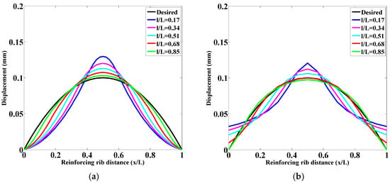
Figure 5.
Deflection analysis results (in the figure, the desired curve represents the ideal deformation of the simply supported beam bending from its initial position to a maximum displacement of 0.1 mm at the center): (a) the calculation model of the equivalent simply supported beam formula and (b) the equivalent simply supported beam finite-element model.
Figure 5 presents a comparative analysis between the finite-element simulation and the calculation using the aforementioned formula. It can be observed that both methods exhibit consistent overall trends. The parabolic region at the center matches well, while the discrepancies at the edge positions are primarily caused by the reactive bending moments between adjacent stiffeners. Longitudinally, as the actuator length increases, the parabolic region occupied by the deflection gradually expands, which aligns more closely with the desired curve. This further validates the rationality of using a spring model to simulate the interaction forces between the mirror stiffener units. To maximize the parabolic region exhibited by the deflection, the size of the actuator support cylinder was minimized in the modeling process in this study.
2.4. Segmented Mirror Modeling and Optimization
The foundation of the optimization model is established by incorporating 12 radially distributed ribs emanating from the center of the mirror’s back surface, each equipped with a single actuator. Additionally, six edge ribs are each furnished with two actuators. This configuration serves as the basis for the optimization model, with the fundamental parameters detailed as Table 2 and Figure 6.

Table 2.
Fundamental modeling parameters.
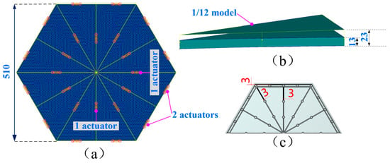
Figure 6.
Schematic diagram of optimized parameters for the fundamental model. Herein, (a) represents the fundamental parametric model, (b) denotes the 1/12 finite-element model, and (c) illustrates the three-dimensional model at a 1/2 scale. (Pink circles indicate the parameter locations in the parametric model, black circles denote the connection structure between adjacent actuators, and the number 3 signifies the size of the reinforcement rib).
In this paper, the fundamental parametric model is constructed using the Patran/Nastran 2019 software suite, and the specific optimization procedure employed is depicted in the following Figure 7.

Figure 7.
Flowchart of the parametric modeling optimization process.
The initial phase of our study involved the optimization of the baseline model, with a focus on the thickness of the edge ribs as the variable parameter. The objective of this optimization was to minimize the residual surface figure error when the curvature radius was adjusted by 100 mm (dROC = 100 mm). Our analysis revealed that the residual surface figure error decreased with an increase in the thickness of the edge ribs. Considering the practical aspects of manufacturing, the maximum edge rib thickness was determined to be 9 mm. The detailed outcomes of the optimization are presented as Table 3 and Figure 8.

Table 3.
Optimization results of edge ribs.
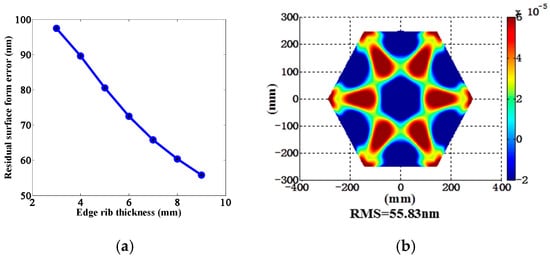
Figure 8.
Optimization results of edge ribs: (a) residual surface error curve after optimization; (b) residual surface error plot for 9 mm edge ribs.
Following the aforementioned optimization outcomes, the arrangement of actuators has been refined. In the parametric model depicted below, the highlighted areas indicate the positions of the actuators. The total number of actuators, the number of edge actuators, the number of actuators on the vertex radial ribs, and the number of actuators on the midpoint radial ribs are defined in the format of “a_b-c-d”. The specific optimization results are shown in Figure 9.
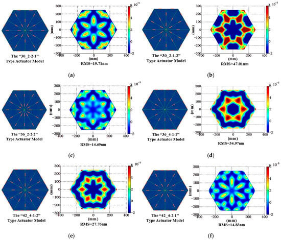
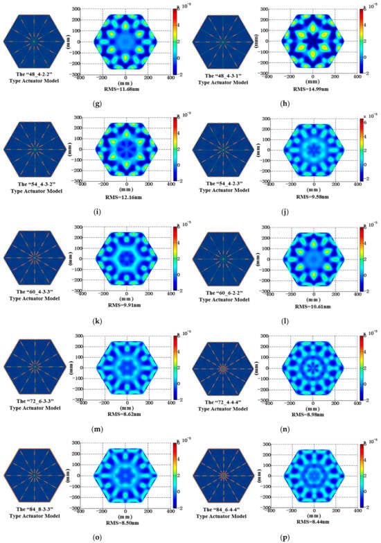
Figure 9.
Parametric modeling and residual surface error analysis of segmented mirrors. The symbols (a–p) denote distinct configurations of varying numbers of actuators, each associated with a specific parametric model and residual surface error profile.
Following the analysis presented, we selected the optimal residual surface error for each actuator configuration and depicted its trend using curves, as illustrated in Figure 10a. It is evident from the figure that there is a generally inverse relationship between residual surface error and the number of actuators. When the number of actuators exceeds 54, the trend of the curve becomes less pronounced. Consequently, we chose the latter four configurations for further optimization. Considering the practicality of engineering implementation, we modified the surface on which the actuators were located to a plane. The resulting changes in residual surface error for these four schemes are presented in Figure 10b.
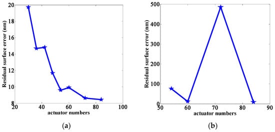
Figure 10.
Curves of residual surface figure error variations: (a) residual surface figure error variation curves across distinct actuator arrangement configurations and (b) residual surface figure error variation curves with actuators positioned on a planar surface.
From Figure 10, it is evident that, when the actuators are relocated to a planar surface, the residual surface figure errors for the 60 and 84 actuator configurations are not significantly different. Considering the complexity of engineering implementation, the configuration with 60 actuators was selected as the final optimized layout for the segmented mirror. A three-dimensional modeling of this configuration is presented in Figure 11.
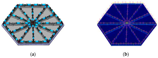
Figure 11.
(a) Three-dimensional model of segmented mirrors and (b) parametric model of the type “60_4-3-3” segmented mirror.
2.5. Calculation of Curvature Radius Variation
The essence of parametric control lies in the computation of the influence functions. The influence functions of all actuators collectively form the matrix H. For a given set of displacements z, the corresponding actuator commands u can be obtained by employing the least-squares method in conjunction with the pseudoinverse matrix, thereby achieving control over the mirror surface shape, as demonstrated below:
In the equation, H represents the matrix of influence function vectors, z is the collection of mirror surface displacements, and u signifies the actuator commands.
In the context of parametric segmented mirror models, the initial sagittal height position of node j is denoted as follows (equivalent to the displacement z previously found):
In the equation, k signifies the asphericity parameter of the non-spherical surface, c corresponds to the curvature at the apex of the non-spherical surface, r denotes the radial coordinate of the light ray in the optical system, and rj specifies the radial distance from the jth node to the optical axis. The sagittal height difference after deformation of the mirror surface node is represented as follows:
In the equation, wj represents the area-weighted coefficient; sj denotes the nominal sagittal height position, while sj* indicates the sagittal height position based on the optimal fit of the curvature radius; dj is the sagittal displacement of node j; and b* signifies the axial movement of the curvature center.
We employed the nonlinear optimization function lsqcurvefit in MATLAB 2014 to minimize the difference in sagittal height before and after the deformation of a segmented mirror. By establishing the relationship between the actuator variables and the radius of curvature, upon successful minimization, the parameter c is obtained, which represents the curvature of the mirror. Consequently, the change in the vertex curvature radius is denoted as follows:
c* denotes the new curvature radius.
3. Analysis of Curvature Radius Variation
In this research, the operational limits of actuators were taken into account by setting the closed-loop upper limit to 15 μm. This constraint was critical to prevent mechanical overload and ensure the longevity of the actuator components. Furthermore, to comprehensively evaluate the performance and response of the actuator system under various conditions, six distinct operational scenarios were defined. The parameter settings for these scenarios, along with the subsequent simulation analysis, are detailed in Table 4 and Figure 12.

Table 4.
Actuator settings under various tests.
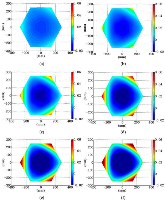
Figure 12.
Variation in curvature radius under six operational conditions: (a) dROC = −29.78 mm; (b) dROC = −60.27 mm; (c) dROC = −88.92 mm; (d) dROC = −119.75 mm; (e) dROC = −147.29 mm; and (f) dROC = −178.45 mm.
Following a comprehensive analysis, we calculated the curvature radius values of segmented mirrors across a spectrum of parameters (reference to specific parameters in Table 5). Concurrently, we constructed the relationship curve between the curvature radius and the actuator change quantity, as illustrated in Figure 13. Utilizing simulation and curve fitting techniques, we ascertained that, within the actuator stroke range of 0–15 μm, the curvature radius underwent a variation of 178.45 mm, demonstrating a highly linear trend. This finding satisfied the requirement for large-scale curvature radius reconfiguration and met the predefined design specifications.

Table 5.
Results of curvature radius variation under different parameter conditions.
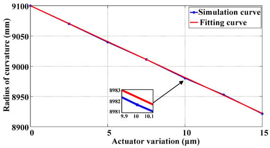
Figure 13.
Curvature radius variation as a function of actuator displacement.
4. Experimental Setup
Silicon Carbide (SiC) is a commonly utilized material for reflective mirrors, renowned for its stiffness, weight, robustness, and high thermal conductivity. In this study, based on the “60_4-3-3” actuator arrangement established in previous discussions, we employed 3D printing technology to manufacture the three-dimensional model designed in the preliminary phase, developing SiC reflective mirror blanks. For a detailed visual representation, refer to Figure 14a.
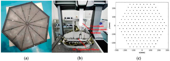
Figure 14.
Segmented mirror curvature radius testing: (a) SiC mirror blank; (b) segmented mirror testbed platform; and (c) data collection point selection.
The experimental procedure involved the use of a coordinate measurement machine (CMM) to conduct curvature radius tests on the segmented mirror. The actuators mounted on the back of the segmented mirror were of the Coremorrow PSt150/7/20 VS12 model, with a nominal voltage range of 0–150 V and a nominal stroke of 19 μm. During testing, the optical axis of the segmented mirror was vertically positioned and secured to the test bench using three bipod mounts. To enhance the reliability of the test outcomes, a multimeter was employed to verify the zero-voltage level of 60 piezoelectric actuators prior to electrical activation, thereby completing the calibration procedure. Subsequently, 185 measurement points were uniformly selected across the surface of the segmented mirror for data acquisition. During this process, the tri-axial coordinate-measuring instrument’s probe initiated at a vertex on the edge of the segmented mirror and executed reciprocating movements parallel to the mirror’s edge. Owing to the hysteresis effect inherent in piezoelectric ceramics, measurements were conducted 30 s after each electrical application. This protocol was followed to ensure that the data collection was comprehensive and accurate; the product and measurement point selection are depicted in Figure 14b,c.
5. Results and Discussion
Based on the coordinates of actual measurement points and employing the equation for aspheric mirror surface profiles, we utilized MATLAB software to perform curve fitting to determine the corresponding curvature radii, as illustrated in Figure 15. For the experimental validation, a closed-loop testing range of 0–15 μm was established for the actuator. The detailed results of the curvature radius testing for the segmented mirror are presented in Table 6. To facilitate a more comprehensive analysis of the curvature radius variation trends, we processed the test outcomes and conducted an analysis on the curvature radius changes corresponding to unit actuator stroke within the interval of 0–15 μm. The associated curve variations are depicted in Figure 16.

Figure 15.
Fitting results of curvature radius: (a) coordinate point extraction; (b) curvature radius fitting chart; and (c) optical mirror front view.

Table 6.
Testing results of curvature radius within the closed-loop range of the segmented mirror.
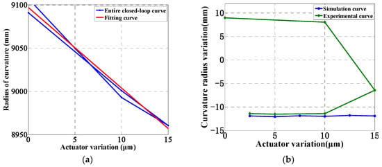
Figure 16.
Curvature radius variation analysis curve, whereby the entire closed-loop curve represents the closed-loop stroke and the closed-loop return stroke: (a) curvature radius change curve and (b) 1 μm stroke corresponds to the change in radius of curvature.
Figure 16 reveals that the curvature radius exhibits a total variation of 146.89 mm across the entire testing range, demonstrating an approximate linear change, which satisfies the requirement for a wide-range adjustment of the curvature radius. Within the 0–10 μm variation interval, the adjustment of the curvature radius is significant and closely matches the simulation results. From 10 μm to the full closed-loop stroke of 15 μm, the optical mirror accurately reflects the true bending conditions, indicating a reduction in the adjustment of the curvature radius per unit stroke. This decrease is primarily attributed to the increased bending moment in the peripheral region of the segmented mirror as the actuator adjustments increase, which, in turn, reduces the bending contribution to the segmented mirror. This observation aligns with the actual stress conditions encountered. Analyzing the entire closed-loop curve trend, the curvature radius changes are approximately symmetrically distributed within the ±10 mm range. The discrepancies between the experimental and simulated results are initially attributed to mechanical assembly errors, stress relief, and hysteresis and degradation of piezoelectric ceramic actuators, posing higher demands on the subsequent design and assembly of high-precision segmented mirror structures.
6. Conclusions
In this study, we address the issues of large-range curvature adjustability and high-precision surface correction for segmented mirrors by conducting research on the design methods for large-scale cascaded hybrid optical mirrors. Employing a parametric modeling approach, we established a simulation model of a segmented mirror with an edge-to-edge distance of 510 mm and a radius of curvature 9100 mm. Based on the principle that the axial strain of piezoelectric ceramics in an electric field environment induces local changes in the curvature radius, we adopted an equivalent simply supported beam model incorporating springs to achieve an optimized actuator layout scheme referred to as “60_4-3-3” and analyzed the relationship between curvature radius changes and the distribution of multiple actuators.
The simulation results indicate that, within a 0–15 μm variation range of the actuator, the segmented mirror can achieve a curvature radius reconfiguration of 178.45 mm, exhibiting a highly linear change relationship. The experimental results demonstrate that, within a 0–15 μm closed-loop stroke range of the actuator, the segmented mirror can achieve a curvature radius reconfiguration of up to 146.89 mm, realizing the design goal of a lightweight reflector with a significantly adjustable curvature radius. Moreover, the curvature radius change corresponding to a 1 μm stroke of the actuator is approximately symmetrically distributed within a ±10 mm closed-loop range. This research provides important technical support for subsequent large-aperture segmented mirror optical system reconfiguration and the establishment of a coupling relationship between curvature radius and surface figure, holding significant engineering practical value.
Author Contributions
Conceptualization, D.S. and Q.H.; methodology, K.Z.; software, K.Z.; validation, L.S.; formal analysis, G.T. and R.G.; and resources, J.H. All authors have read and agreed to the published version of the manuscript.
Funding
This research was funded by the Key Civil Space Program, grant number D040101.
Institutional Review Board Statement
Not applicable.
Informed Consent Statement
Not applicable.
Data Availability Statement
The data presented in this study are available upon request from the corresponding author.
Conflicts of Interest
The authors declare no conflicts of interest.
References
- Gallagher, B.B.; Knight, J.S.; Acton, D.S.; Smith, K.Z.; Wolf, E.; Coppock, E.; Tersigni, J.; Comeau, T.; Chonis, T.S. Characterization and calibration of the James Webb space telescope mirror actuators fine stage motion. Proc. SPIE 2018, 10698, 106983S. [Google Scholar]
- Wu, S.; Dong, J.; Xu, S.; Xu, B. Overview of Active Support Technology for Main Mirror of Segmented Telescopes. Laser Optoelectron. Prog. 2021, 58, 72–83. [Google Scholar]
- Liao, C.; Yu, F.; Liu, C. Research on the Decoupling Control Method of Segmented Deformable Mirror Surface Shape. Spacecr. Recovery Remote Sens. 2022, 43, 69–78. [Google Scholar]
- Jiang, H. Overview of adaptive optics development. Opto-Electron. Eng. 2018, 45, 170489. [Google Scholar]
- Guan, C.; Zhang, X.; Deng, J.; Xue, L.; Zhang, Y.; Zhou, H.; Fan, X.; Cheng, L.; Fan, J.; He, G.; et al. Deformable mirror technologies at Institute of Optics and Electronics, Chinese Academy of Sciences. Opto-Electron. Eng. 2020, 47, 200337. [Google Scholar]
- Chaney, D.M.; Hadaway, J.B.; Lewis, J.A. Cryogenic radius of curvature matching for the JWST primary mirror segments. In Astronomical and Space Optical Systems; International Society for Optics and Photonics: Bellingham, DC, USA, 2009; Volume 7439, p. 743916. [Google Scholar]
- Wolf, E.M.; Gallagher, B.B.; Knight, J.S.; Chonis, T.S.; Sullivan, J.F.; Smith, K.Z.; Rudeen, A.; Babcock, K.; Hardy, B.; Barto, A.; et al. JWST mirror and actuator performance at cryo-vacuum. In Proceedings of the SPIE Astronomical Telescopes + Instrumentation, Austin, TX, USA, 10–15 June 2018; pp. 84–97. [Google Scholar]
- Redding, D. Large Segmented Apertures in Space: Active vs. Passive. 2018. Available online: https://kiss.caltech.edu/special_events/JPL_MPIA/presentations/2_Redding.pdf (accessed on 9 April 2018).
- Perrin, M.D.; Acton, D.S.; Lajoie, C.P.; Knight, J.S.; Lallo, M.D.; Allen, M.; Baggett, W.; Barker, E.; Comeau, T.; Coppock, E.; et al. Preparing for JWST Wavefront Sensing and Control Operations. Astron. Telesc. + Instrum. 2016, 9904, 142–160. [Google Scholar]
- Hirose, M.; Kumeta, A.; Miyamura, N.; Sato, S.; Mizutani, T.; Kimura, T. Wavefront Correction Using MEMS Deformable Mirror for Earth Observation Satellite with Large Segmented Telescope. Proc. Adapt. Opt. Syst. VII 2020, 11448, 1440–1448. [Google Scholar]
- Kimura, T.; Mizutani, T.; Shirasawa, Y.; Sakai, M.; Kumeta, A.; Sato, S.; Miyamura, N.; Iwasaki, A. Geostationary Earth Observation Satellite with Large Segmented Telescope. In Proceedings of the IGARSS 2019-2019 IEEE International Geoscience and Remote Sensing Symposium, Yokohama, Japan, 28 July–2 August 2019; pp. 5895–5897. [Google Scholar]
- Fujii, Y.; Uno, T.; Ariki, S.; Suehiro, K.; Itakura, S.; Imaki, M.; Mizutani, T.; Sato, S.; Yanagase, K.; Yasuda, S.; et al. Experimental Study of 3.6-meter Segmented-aperture Telescope for Geostationary Earth Observation Satellite. In Proceedings of the International Conference on Space Optics—ICSO 2020, Virtual, 30 March–2 April 2021; Volume 11852, pp. 1034–1043. [Google Scholar]
- Fowler, J.; Haffert, S.Y.; van Kooten, M.A.; Landman, R.; Bidot, A.; Hours, A.; N’Diaye, M.; Absil, O.; Altinier, L.; Baudoz, P.; et al. Visible extreme adaptive optics on extremely large telescopes: Towards detecting oxygen in Proxima Centauri b and analogs. Opt. Eng. + Appl. 2023, 12680, 594–604. [Google Scholar]
- Haber, A. A novel method for adaptive control of deformable mirrors. In Adaptive Optics and Wavefront Control for Biological Systems VIII; SPIE: Bellingham, WA, USA, 2022. [Google Scholar]
- Su, D.; Cui, X. Active optics in LAMOST. Chin. J. Astron. Astrophys. 2004, 4, 1. [Google Scholar]
- Chen, J.; Wang, C.; Huo, T. Research on detection method of large-aperture aspheric surface by laser tracker. J. Appl. Opt. 2021, 42, 299–303. [Google Scholar]
- Pang, Z.; Zong, X.; Du, J. A method measuring geometric parameters for large-aperture aspheric surface with the laser tracker. Spacecr. Recovery Remote Sens. 2020, 41, 47–59. [Google Scholar]
- Shi, Y.; Niu, D.; Wang, M.; Pan, C. Research on Micro-displacement Actuator for High Precision Mirror Position Control. Astron. Res. Technol. 2023, 20, 250–257. [Google Scholar]
- Liu, Y.; Zhang, J.; Yang, F. Review on primary mirror segment position actuator of large optical telescope. Laser Infrared 2021, 51, 131–140. [Google Scholar]
- Jordan, E.O. Design and Shape Control of Lightweight Mirrors for Dynamic Performance and Athermalization. Master’s Thesis, Massachusetts Institute of Technology, Cambridge, MA, USA, 2007. [Google Scholar]
- Horvath, N.; Davies, M. Advancing lightweight mirror design: A paradigm shift in mirror preforms by utilizing design for additive manufacturing. Appl. Opt. 2021, 60, 681. [Google Scholar] [CrossRef] [PubMed]
- Cohan, L.E. Integrated Modeling and Design of Lightweight, Active Mirrors for Launch Survival and On-Orbit Performance. Ph.D. Thesis, Massachusetts Institute of Technology, Cambridge, MA, USA, 2010. [Google Scholar]
- Li, A.; Jiang, X.; Sun, J.; Bian, Y.; Wang, L.; Liu, L. Radial support analysis for large-aperture rotating wedge prism. Opt. Laser Technol. 2012, 44, 1881–1888. [Google Scholar] [CrossRef]
- Duma, V.-F.; Duma, M.-A. Optomechanical Analysis and Design of Polygon Mirror-Based Laser Scanners. Appl. Sci. 2022, 12, 5592. [Google Scholar] [CrossRef]
Disclaimer/Publisher’s Note: The statements, opinions and data contained in all publications are solely those of the individual author(s) and contributor(s) and not of MDPI and/or the editor(s). MDPI and/or the editor(s) disclaim responsibility for any injury to people or property resulting from any ideas, methods, instructions or products referred to in the content. |
© 2025 by the authors. Licensee MDPI, Basel, Switzerland. This article is an open access article distributed under the terms and conditions of the Creative Commons Attribution (CC BY) license (https://creativecommons.org/licenses/by/4.0/).