Article

Optical Differentiation and Edge Detection Based on Birefringence of Uniaxial Crystals

1
Department of Physics and Engineering Technology, Guilin Normal College, Guilin 541199, China
2
School of Electronic Information and Automation, Guilin University of Aerospace Technology, Guilin 541004, China
*
Author to whom correspondence should be addressed.
Photonics 2025, 12(4), 336; https://doi.org/10.3390/photonics12040336
Submission received: 2 March 2025 / Revised: 22 March 2025 / Accepted: 30 March 2025 / Published: 2 April 2025

Abstract

:
Optical differential operations can directly extract edge information from images and have significant application potential in fields such as image processing and object recognition. In this work, we propose an optical spatial differentiator based on the birefringence effect of uniaxial crystals. The system comprises two orthogonal polarizers and a uniaxial crystal, offering advantages of structural simplicity, operational stability, low cost, and seamless compatibility with conventional optical systems. Experimental results demonstrate that the proposed differentiator achieves clear edge imaging for both amplitude and phase objects, while also enabling dark-field differential imaging of transparent biological cells, thereby substantially enhancing imaging quality and contrast. This efficient and robust design provides a promising solution for advancing optical differentiation techniques in applications ranging from data processing to biomedical imaging.

1. Introduction

The rapid development of fields such as artificial intelligence, autonomous driving, and big data has brought about an immense amount of data, which places higher demands on computing tools. In recent years, with the development of ultra large-scale integrated circuits, the size of electronic computers has been continuously reduced, and data processing speed has been greatly improved [1]. However, as electronic devices are gradually constrained by physical limitations such as quantum effects, the speed of improving low-power and miniaturization of digital computing circuits is becoming slower and slower. In addition, traditional analog signal processing requires analog-to-digital conversion, signal processing, and digital-to-analog conversion processes. The inevitable conversion delay and high power consumption of electronic devices make traditional analog computing incapable of large-scale information parallel processing [2]. Therefore, researchers are committed to developing new computing systems to compensate for the many shortcomings of traditional electronic computing systems, among which the construction of all-optical systems using optical signals as information carriers has attracted increasing attention from scholars [3]. Optical signal processing systems are divided into two types: digital operation and analog operation. Among them, optical simulation computing has developed rapidly due to its information processing advantages of large-scale parallel computing, low power consumption, and ultra-fast response speed [4,5], especially as one of the optical simulation calculations, spatial differentiation, can be directly used for image edge extraction, showing great potential in edge detection [6].
During the past few years, various methods have been proposed to perform optical spatial differentiation. Optical spatial differentiation based on optical metamaterials [7], metasurfaces [8,9,10,11,12,13,14,15], or grating [16,17,18,19] has demonstrated superior performance and simpler systems compared to traditional systems (including lenses and spatial filters). Bezus et al. [20] proposed using a novel dielectric ridge structure to achieve spatial differentiation. Youssefi and Xu et al. [21,22] reported spatial differentiation based on the Brewster effect. In addition, Xu et al. [23] also achieved spatial differentiation through the Goos–Hänchen shift generated by the reflection of light at the interface. The method based on the spin Hall effect was also used for edge detection and differential microscopy [24,25,26]. Zhu and Song et al. [27,28] discussed and implemented spatial differentiation from the perspective of topological photonics. By utilizing multilayered metallic and hydrogel stacks construction, Dai et al. [29] proposed a method for dynamic edge-enhanced imaging. Ji et al. [30] achieved optical spatial differentiation based on the photon spin Hall effect generated by uniaxial crystal interface reflection. They found that in elliptic-hyperbolic crystals, the photonic spin Hall effect can be significantly enhanced, thereby achieving an enhancement in spatial differentiation contrast when the beam is reflected at the Brewster angle. Two years ago, based on the spin–orbit coupling effect of uniaxial crystals, broadband analog computing and achromatic spatial differentiation imaging were realized by Zhu’s group [31]. Unlike Reference [30], their experimental setup inserts a uniaxial crystal in front of the camera of a conventional microscope, utilizing the intrinsic spin–orbit coupling generated during light propagation in a natural thin crystal to achieve an isotropic differential image.
Optical spatial differentiation methods each exhibit unique advantages in different application scenarios, yet they also come with inherent limitations. For instance, metasurfaces or metamaterials often suffer from high manufacturing costs and may have low diffraction efficiency. The fabrication and alignment of gratings demand extreme precision, as even minor misalignments can significantly degrade differentiation performance. Meanwhile, methods based on the photonic spin Hall effect or Goos–Hänchen shift typically face challenges such as strong medium dependency and stringent requirements for optical path adjustments. In this work, we propose a method for performing optical spatial differentiation based on the birefringence of uniaxial crystals. This optical spatial differentiator consists of two orthogonal polarizers and a uniaxial crystal. Theoretical and experimental analysis results indicate that this system can perform optical differential operations and realize the edge detection of objects and high-contrast imaging of biological cells. The optical spatial differentiator has the advantages of simplicity, stability, low cost, and good compatibility with existing optical systems and technologies.

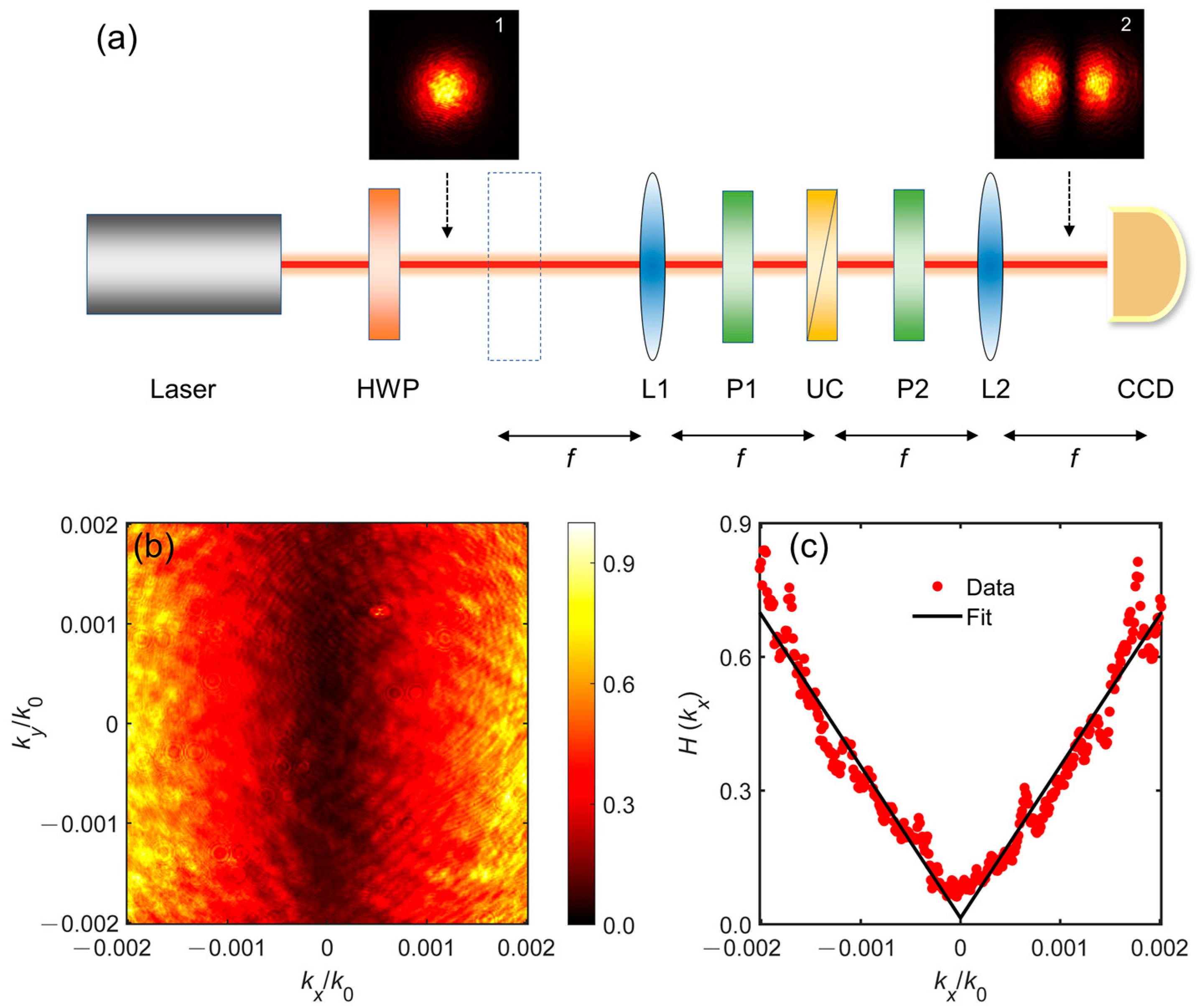
2. Theoretical Model

The schematic diagram of using uniaxial crystals to construct an optical spatial differentiator is shown in Figure 1. We first analyze the principle of performing optical spatial differentiation with uniaxial crystals. Due to anisotropy, uniaxial crystals can realize specific manipulation of the polarization of light. In a uniaxial crystal, the dielectric constant of one axis is different from the other two axes, that is, ε 1 = ε 2 = n o 2 and ε 3 = n e 2 n o 2 , where n o and n e represent the ordinary and extraordinary refractive indices, respectively [32]. The prism used here is composed of two wedge-shaped uniaxial crystals with crystal axes perpendicular to each other. Due to the different refractive indices of different polarization components, the incident linearly polarized light splits into different polarization components after refracting, as shown in the inset of Figure 1. This phenomenon is also known as the birefringence effect. Here, we consider a beam of 45° linearly polarized light that vertically illuminates a uniaxial crystal. Equal amounts of horizontally polarized light (H) and vertically polarized light (V) split at a splitting angle of γ. The splitting shift x is generated by two orthogonal polarized light beams after transmitting a distance z:
x = z t a n γ 2 .
The above beam-splitting evolution is very important for performing spatial differentiation. By controlling the propagation distance, one can precisely control the splitting shift. Consider the incident light field E i n x , y as
E i n x , y = E i n x , y e D ,
where e D = 1 1 / 2 represents the unit vector in the diagonal direction. After propagating through the uniaxial crystal, the output optical field E o u t x , y is
E o u t x , y = E i n x + x , y 2 e x + E i n x x , y 2 e y .
If we set the polarization axis of the second Glan polarizer to 45 ° orthogonal to the incident polarization, the output field can be expressed as
E o u t x , y = 1 2 2 1 1 1 1 E i n x + x , y E i n x x , y = E i n x + x , y E i n x x , y 2 e A ,
where e A = 1 1 / 2 is the unit vector in the anti-diagonal direction. From Equations (2) and (4), one can see that the polarization component undergoes splitting through the uniaxial crystal. Additionally, the action of the orthogonal polarizer causes destructive interference in the output field.
It should be noted that not all beam-splitting evolution processes can achieve optical spatial differentiation. The condition must be that the shear distance x is small enough to satisfy the differential form. Fortunately, in the birefringence effect of uniaxial crystal, the beam-splitting angle γ is usually very small and in the range of 100   μ r a d [33]. In this case, the splitting shift x is very small. When the propagation distance z = 250   m m , one can obtain x = 12.5   μ m . When the displacement Δx is much smaller than the characteristic spatial scale of the input optical field, the higher-order terms in the Taylor expansion can be neglected. Under this condition, Equation (4) can be approximately simplified into the form of a first-order differential
E o u t x , y x E i n x
Equation (5) shows that the beam splitting caused by the birefringence of uniaxial crystal can realize differential operation. The contrast of optical differential imaging depends on the small shift in beam component splitting. According to Equation (2), the birefringent splitting shift x can be precisely controlled by the propagation distance z. The splitting shift ∆x acts as the differentiation step size, where a smaller value yields a closer approximation to the true derivative. Therefore, one can achieve high contrast differential imaging through precise control of the splitting shift. Using the birefringence of a uniaxial crystal, the optical field is split into orthogonally polarized components with a micro-displacement. Polarization interference is then employed to extract gradient information, thereby achieving optical spatial differentiation. This process eliminates complex computational steps, relying solely on the geometric configuration and polarization properties of physical components, offering an innovative solution for high-speed, low-power edge detection.
Although all three methods require the use of uniaxial crystals, our method differs fundamentally from those described in refs. [30,31]. Specifically, ref. [30] achieved optical spatial differentiation through the spin splitting of light reflected at the surface of a uniaxial crystal, while ref. [31] proposed embedding an optical vortex in the image field by leveraging the intrinsic spin–orbit coupling of the crystal to perform second-order topological spatial differentiation. Furthermore, traditional differential systems typically require additional components such as filters to construct complex optical paths. In contrast, our spatial differentiator consists solely of two polarizers and one uniaxial crystal, offering the advantages of structural simplicity, stability, low cost, and seamless compatibility with existing optical systems and technologies.
This class of optical spatial differentiators enables not only analog signal processing [7] and image edge detection [8], but also facilitates applications including transparent biological sample imaging [31,34], wavefunction reconstruction [35,36], three-dimensional reconstruction [14], and quantum imaging [37]. To validate these capabilities, we constructed an experimental system based on this differentiator and experimentally demonstrated its efficacy in edge detection and transparent biological sample imaging.

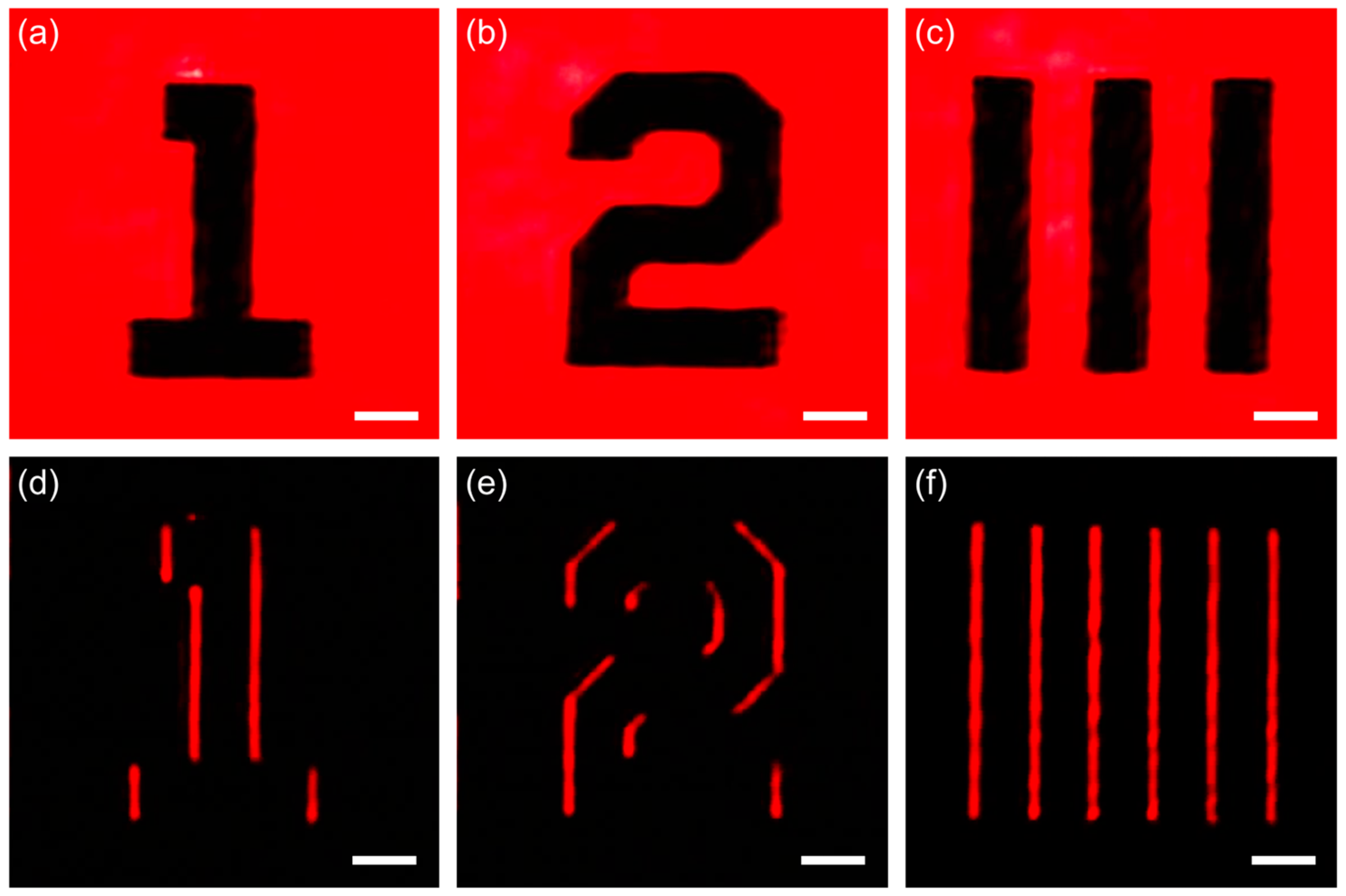
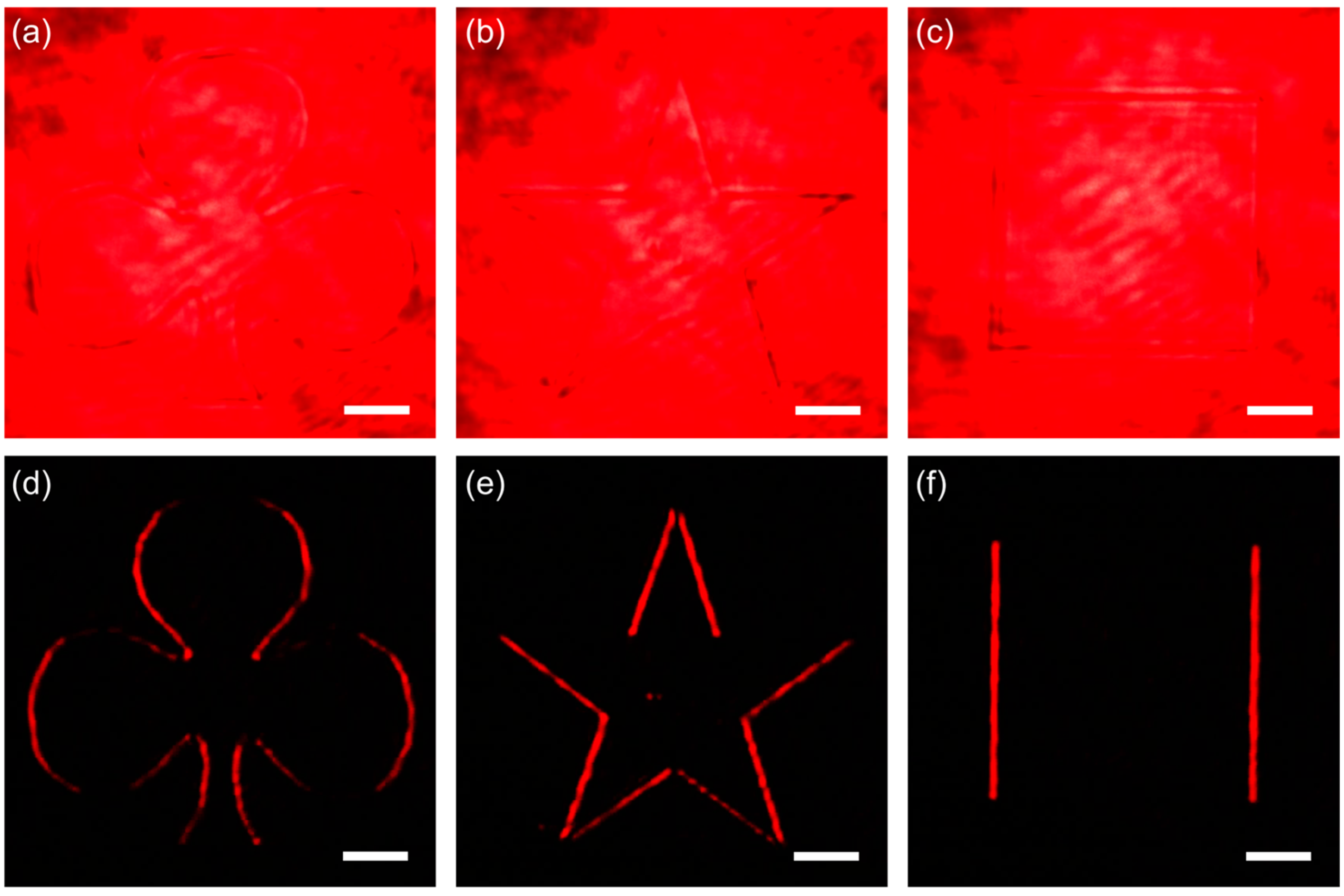
3. Experimental Results

To prove the spatial differentiation in Equation (5), we first measure the spatial transfer function under a Gaussian beam illumination. The spatial transfer function is defined as the ratio of the output field to the incident field H ( k x , k y ) = E o u t ( k x , k y ) / E i n ( k x , k y ) [8]. The incident Gaussian beam can be written as
E i n k x , k y = ω 0 2 π exp ω 0 2 k x 2 + k y 2 4
where ω 0 is the waist width of the beam. The experimental setup for measurement is shown in Figure 2a. The light source is a He-Ne laser with a wavelength of 633 nm. The half-wave plate (HWP) is used to adjust the incident light intensity. The laser beam passes through a 175 mm lens, L1, and is then incident on a spatial differentiator (consisting of two orthogonal polarizers and a uniaxial crystal). The prism consists of two wedge-shaped quartz crystals, each with a wedge angle of 5°. The optical axis of the first wedge is oriented 45° to the prism surface, while that of the second wedge is parallel to the prism surface. The overall dimensions of the prism are 30 × 30 × 3 mm. The split beam is collected by the second focusing lens, L2, and captured by a CCD camera. This experimental setup is also suitable for the edge detection of images, where the dashed box represents the position of the detected object. By measuring the intensity distribution of the output and incident fields (insets 1 and 2 in Figure 2a), the spatial transfer function can be easily calculated, as shown in Figure 2b. Figure 2c shows the transfer function when k y = 0 , and the solid line is obtained by fitting experimental data. It can be clearly seen that the spatial transfer function is linearly dependent on k x . Therefore, it can be proven that the implemented differentiation is a first-order spatial differentiation.
It should be noted that our experimental setup remains feasible with lasers of other wavelengths. Although the ordinary refractive index n o and extraordinary refractive index n e of the uniaxial crystal are wavelength-dependent (i.e., exhibiting dispersion), and the beam-splitting angle relies on the refractive index difference between the ordinary and extraordinary light, Equation (1) indicates that we can compensate for the splitting shift x by rationally selecting crystal materials and adjusting experimental parameters (e.g., the crystal thickness and lens). This ensures compliance with the differentiation approximation conditions. Consequently, this method exhibits broadband capability and offers flexibility for specific applications.
The realized spatial differentiation can be used for edge detection on objects. To prove this point, we conducted experimental verification. The experimental results are shown in Figure 3. The sample we used was a resolution test target (USAF-1951) placed at the front focal length of L1, as indicated by the dashed box in Figure 2a. Firstly, by rotating P2 and P1 so that they were not orthogonal, we could obtain a bright-field image containing object information, as shown in Figure 3a–c. Next, by continuing to rotate P2 so that it was orthogonal to P1, the edge contour of the object was clearly imaged, as demonstrated in Figure 3d–f. It should be noted that the edges of the image were only displayed horizontally, as the implemented spatial differentiation was one-dimensional and along the x -direction.
The objects imaged above belong to amplitude objects. However, the proposed scheme also works for pure phase objects. To demonstrate this, we replaced the previous amplitude target with a pure phase object etched with 200 nm patterns. Similarly, bright-field images were obtained when the polarization axes of P1 and P2 were parallel, as shown in Figure 4a–c. In a bright field, phase objects are almost invisible due to their extremely low contrast. In the dark field (where P2 and P1 were orthogonal), the contour of the phase object was presented with high contrast, as demonstrated in Figure 4d–f. Therefore, optical spatial differentiation provides an effective imaging solution for transparent samples. The reason spatial differentiation can achieve edge detection is that phase gradients often appear at the edges of objects [8].
In biomedical imaging, some tissues and cells often have low contrast when directly imaged due to weak scattering and absorption. Next, we demonstrate that optical spatial differentiation using uniaxial crystals can also achieve dark-field differential imaging of transparent cells. The experimental setup, shown in Figure 5a, simply added a confocal microscopy system at the position indicated by the dashed box in Figure 2a. The objective lens parameters used were a magnification of 10 × and a numerical aperture of N A = 0.25 . We selected unstained paramecium cells, and their bright-field images are shown in Figure 5b–d. One can see that the cell morphology was difficult to distinguish or even invisible in a bright field. In dark-field differential imaging, the contours of cells were clearly visible and had high contrast, as shown in Figure 5e–g. Not only the edge of the cell, but also the nucleus and other organelles inside can be clearly distinguished, which is very difficult in a bright field. Figure 5h,i show the cross-sectional intensity distribution along the dashed lines in Figure 5d,g, providing a more intuitive demonstration of the advantages of dark-field differential imaging.
It should be noted that ambient light or reflected light in the optical path can reduce the signal-to-noise ratio of an image, so it is advisable to use light shields and diaphragms to block stray light. Additionally, as we were using a one-dimensional differentiation system, it was necessary to rotate the sample to an appropriate angle for imaging to achieve the best results.
It is worth mentioning that the experimental samples used in this method must be transparent, as the imaging process relies on phase gradients rather than absorption contrast. Samples containing high-frequency structures may induce interference from higher-order terms. Although we focused on 1D spatial optical differentiation based on the birefringence of uniaxial crystals, this approach can be extended to achieve 2D differentiation through cascaded orthogonal differentiators. The optical spatial differential system based on the birefringence effect of uniaxial crystals proposed by us has the advantages of low cost, high efficiency, a simple optical path, and stability. Moreover, based on the uniaxial crystal birefringence differentiator, existing optical systems and technologies can be well compatible, which is conducive to promoting the application of optical differentiation in fields such as image processing and object recognition.

4. Conclusions

In conclusion, we present a compact optical spatial differentiator leveraging the birefringence effect of uniaxial crystals for edge detection. Theoretical analysis demonstrates that the anisotropy of uniaxial crystals enables precise control over the separation of orthogonal polarization components, thereby facilitating differential operations. Guided by these insights, we developed a stable, low-cost system comprising two orthogonal polarizers and a uniaxial crystal. Experimental results confirm that the proposed differentiator achieves high-contrast edge imaging for both amplitude and phase objects. In biomedical imaging, where weakly scattering/absorbing tissues and cells inherently suffer from low contrast, our method overcomes this limitation by enabling dark-field differential imaging of transparent specimens, enhancing image quality and contrast. Future research can aim to achieve two-dimensional differentiation, higher-order differentiation, and multi-wavelength applications, while integrating new materials, novel physical effects, and interdisciplinary approaches, to drive the transition of this optical spatial differentiation technology from laboratory to practical applications. We believe that this simple and efficient system will provide a preferred solution for the application of optical differentiation in fields such as data processing and biological imaging.

Author Contributions

Conceptualization, X.C. and X.Y.; methodology, X.C.; software, P.H.; validation, X.C., X.Y. and X.T.; formal analysis, P.H.; investigation, X.T. and X.Y.; resources, P.H.; data curation, X.T.; writing—original draft preparation, X.C. and X.Y.; writing—review and editing, X.C.; visualization, X.T.; supervision, X.Y.; project administration, X.Y.; funding acquisition, X.C. and X.Y. All authors have read and agreed to the published version of the manuscript.

Funding

This research was funded by the Guangxi Key Research and Development Program (Grant No: Guike AB25069032); the School-level Research Program of Guilin Normal College (Grant No: KYA202303); and the Guilin University of Aerospace Technology Doctoral Research Start-up Fund (Grant No: KX202206701).

Institutional Review Board Statement

Not applicable.

Informed Consent Statement

Not applicable.

Data Availability Statement

Data underlying the results are all presented in this paper.

Conflicts of Interest

The authors declare no conflicts of interest.

References

  1. Hansson, S.O. Technology and mathematics. Philos. Technol. 2020, 33, 117–139. [Google Scholar]
  2. Zangeneh-Nejad, F.; Sounas, D.L.; Alù, A.; Fleury, R. Analogue computing with metamaterials. Nat. Rev. Mater. 2021, 6, 207–225. [Google Scholar]
  3. Huang, Y.D. Twenty years of photonics. ACS Photonics 2021, 8, 384–385. [Google Scholar]
  4. Vourkas, I.; Stathis, D.; Sirakoulis, G.C. Massively parallel analog computing: Ariadne’s thread was made of memristors. IEEE Trans. Emerg. Top. Comput. 2018, 6, 145–155. [Google Scholar]
  5. Santagiustina, M.; Chin, S.; Primerov, N.; Ursini, L.; Thévenaz, L. All-optical signal processing using dynamic Brillouin gratings. Sci. Rep. 2013, 3, 1594. [Google Scholar]
  6. He, S.; Wang, R.; Luo, H. Computing metasurfaces for all-optical image processing: A brief review. Nanophotonics 2022, 11, 1083–1108. [Google Scholar] [PubMed]
  7. Silva, A.; Monticone, F.; Castaldi, G.; Galdi, V.; Alù, A.; Engheta, N. Performing mathematical operations with metamaterials. Science 2014, 343, 160–163. [Google Scholar]
  8. Zhou, J.; Qian, H.; Chen, C.F.; Zhao, J.; Li, G.; Wu, Q.; Luo, H.; Wen, S.; Liu, Z. Optical edge detection based on high-efficiency dielectric metasurface. Proc. Natl. Acad. Sci. USA 2019, 116, 11137–11140. [Google Scholar]
  9. Cordaro, A.; Kwon, H.; Sounas, D.; Koenderink, A.F.; Alù, A.; Polman, A. High-index dielectric metasurfaces performing mathematical operations. Nano Lett. 2019, 19, 8418–8423. [Google Scholar]
  10. Komar, A.; Aoni, R.A.; Xu, L.; Rahmani, M.; Miroshnichenko, A.E.; Neshev, D.N. Edge detection with Mie-resonant dielectric metasurfaces. ACS Photonics 2021, 8, 864–871. [Google Scholar]
  11. He, Q.; Zhang, F.; Pu, M.B.; Ma, X.L.; Li, X.; Jin, J.J.; Guo, Y.H.; Luo, X.G. Monolithic metasurface spatial differentiator enabled by asymmetric photonic spin-orbit interactions. Nanophotonics 2020, 10, 741–748. [Google Scholar] [CrossRef]
  12. Kwon, H.; Cordaro, A.; Sounas, D.; Polman, A.; Alù, A. Dual-polarization analog 2D image processing with nonlocal metasurfaces. ACS Photonics 2020, 7, 1799–1805. [Google Scholar] [CrossRef]
  13. Wang, R.S.; He, S.S.; Chen, S.Z.; Shu, W.X.; Wen, S.C.; Luo, H.L. Computing metasurfaces enabled chiral edge image sensing. iScience 2022, 25, 104532. [Google Scholar] [CrossRef] [PubMed]
  14. Xu, D.; Xu, W.; Yang, Q.; Zhang, W.; Wen, S.; Luo, H. All-optical object identification and three-dimensional reconstruction based on optical computing metasurface. Opto-Electron. Adv. 2023, 6, 230120. [Google Scholar] [CrossRef]
  15. Zong, M.; Liu, Y.; Lü, J.; Zhang, S.; Xu, Z. Two-dimensional optical differentiator for broadband edge detection based on dielectric metasurface. Opt. Lett. 2023, 48, 1902–1905. [Google Scholar] [CrossRef]
  16. Golovastikov, N.V.; Bykov, D.A.; Doskolovich, L.L. Resonant diffraction gratings for spatial differentiation of optical beams. Quantum Electron. 2014, 44, 984–988. [Google Scholar] [CrossRef]
  17. Parthenopoulos, A.; Darki, A.A.; Jeppesen, B.R.; Dantan, A. Optical spatial differentiation with suspended subwavelength gratings. Opt. Express 2021, 29, 6481–6494. [Google Scholar] [CrossRef]
  18. Fang, Y.S.; Ruan, Z.C. Optical spatial differentiator for a synthetic three-dimensional optical field. Opt. Lett. 2018, 43, 5893–5896. [Google Scholar] [CrossRef]
  19. Xu, C.Y.; Wang, Y.L.; Zhang, C.; Dagens, B.; Zhang, X. Optical spatiotemporal differentiator using a bilayer plasmonic grating. Opt. Lett. 2021, 46, 4418–4421. [Google Scholar] [CrossRef]
  20. Bezus, E.A.; Doskolovich, L.L.; Bykov, D.A.; Soifer, V.A. Spatial integration and differentiation of optical beams in a slab waveguide by a dielectric ridge supporting high-Q resonances. Opt. Express 2018, 26, 25156–25165. [Google Scholar] [CrossRef]
  21. Xu, D.; He, S.; Zhou, J.; Chen, S.; Wen, S.; Luo, H. Optical analog computing of two-dimensional spatial differentiation based on the Brewster effect. Opt. Lett. 2020, 45, 6867–6870. [Google Scholar] [PubMed]
  22. Youssefi, A.; Zangeneh-Nejad, F.; Abdollahramezani, S.; Khavasi, A. Analog computing by Brewster effect. Opt. Lett. 2016, 41, 3467–3470. [Google Scholar]
  23. Xu, D.; He, S.; Zhou, J.; Chen, S.; Wen, S.; Luo, H. Goos-Hänchen effect enabled optical differential operation and image edge detection. Appl. Phys. Lett. 2020, 116, 211103. [Google Scholar] [CrossRef]
  24. Zhu, T.; Lou, Y.; Zhou, Y.; Zhang, J.; Huang, J.; Li, Y.; Luo, H.; Wen, S.; Zhu, S.; Gong, Q.; et al. Generalized spatial differentiation from the spin Hall effect of light and its application in image processing of edge detection. Phys. Rev. Appl. 2019, 11, 034043. [Google Scholar]
  25. He, S.; Zhou, J.; Chen, S.; Shu, W.; Luo, H.; Wen, S. Spatial differential operation and edge detection based on the geometric spin Hall effect of light. Opt. Lett. 2020, 45, 877–880. [Google Scholar]
  26. Wang, R.; He, S.; Luo, H. Photonic spin-Hall differential microscopy. Phys. Rev. Appl. 2022, 18, 044016. [Google Scholar] [CrossRef]
  27. Zhu, T.; Guo, C.; Huang, J.; Wang, H.; Orenstein, M.; Ruan, Z.; Fan, S. Topological optical differentiator. Nat. Commun. 2021, 12, 680. [Google Scholar] [CrossRef] [PubMed]
  28. Song, B.W.; Wen, S.C.; Shu, W.X. Topological differential microscopy based on the spin-orbit interaction of light in a natural crystal. ACS Photonics 2022, 9, 3987–3994. [Google Scholar] [CrossRef]
  29. Dai, C.; Li, Z.; Shi, Y.; Wan, S.; Hu, W.; Li, Z. Hydrogel-scalable nanoslide for switchable optical spatial-frequency processing. Laser Photon. Rev. 2023, 17, 2200368. [Google Scholar] [CrossRef]
  30. Ji, Y.W.; Ma, X.K.; Hu, H.J.; Li, X.Z. Enhanced edge detection based on spin Hall effect in the uniaxial crystal. Front. Phys. 2022, 10, 862156. [Google Scholar]
  31. Yang, H.; Xie, W.; Chen, H.; Xie, M.; Tang, J.; Zheng, H.; Zhong, Y.; Yu, J.; Chen, Z.; Zhu, W. Spin-orbit optical broadband achromatic spatial differentiation imaging. Optica 2024, 11, 1008. [Google Scholar]
  32. Born, M.; Wolf, E. Principles of Optics: Electromagnetic Theory of Propagation, Interference and Diffraction of Light; Elsevier: Amsterdam, The Netherlands, 2013. [Google Scholar]
  33. Shaked, N.T.; Zalevsky, Z.; Satterwhite, L.L. Biomedical Optical Phase Microscopy and Nanoscopy; Academic Press: Cambridge, MA, USA, 2012. [Google Scholar]
  34. Liang, X.; Zhu, D.; Dai, Q.; Xie, Y.; Zhou, Z.; Peng, C.; Li, Z.; Chen, P.; Lu, Y.Q.; Yu, S.; et al. All-Optical Multi-Order Multiplexing Differentiation Based on Dynamic Liquid Crystals. Laser Photon. Rev. 2024, 18, 2400032. [Google Scholar] [CrossRef]
  35. Yang, Q.; Xu, D.; Chen, S.; Wen, S.; Luo, H. Reconstruction of wave function via spin-orbit interaction of light. Phys. Rev. Appl. 2023, 20, 054011. [Google Scholar]
  36. Zhu, J.; Wang, A.; Liu, X.; Liu, Y.; Zhang, Z.; Gao, F. Reconstructing the wave function through the momentum weak value. Phys. Rev. A 2021, 104, 032221. [Google Scholar]
  37. Liu, J.; Yang, Q.; Chen, S.; Xiao, Z.; Wen, S.; Luo, H. Intrinsic Optical Spatial Differentiation Enabled Quantum Dark-Field Microscopy. Phys. Rev. Lett. 2022, 128, 193601. [Google Scholar]
Figure 1. Schematic diagram of constructing a spatial differentiator using uniaxial crystals. The two orthogonal arrows indicate the polarization axes of the respective polarizers. A spatial differentiator is formed by two orthogonal polarizers and a uniaxial crystal (UC), enabling edge detection on the input image. The inset provides a detailed illustration of the manipulation of polarized light by the uniaxial crystal.
Photonics 12 00336 g001
Figure 2. Measurement of spatial transfer function. (a) Experimental setup. Laser, He-Ne laser with a wavelength of 633 nm; HWP, half-wave plate; The dashed line box indicates the position of the object to be measured; P1 and P2, Glan laser polarizers; L1 and L2, lenses with effective focal lengths of 175 mm and 250 mm, respectively; UC, uniaxial crystal; CCD, charge-coupled device. Insets (1 and 2) represent the intensity distribution of the light field at the positions indicated by arrows, respectively. (b) Experimental results of spatial transfer function. (c) The measured spatial transfer function for k y = 0 . The solid line is the result of fitting based on experimental data.
Photonics 12 00336 g002
Figure 3. Edge detection of different amplitude targets. (ac) Bright-field images acquired under parallel polarizer configuration. (df) Corresponding edge-enhanced images obtained with orthogonal polarizers. Scale bar: 200 μm.
Photonics 12 00336 g003
Figure 4. Edge detection of different phase targets. (ac) Bright-field images acquired under parallel polarizer configuration. (df) Corresponding edge-enhanced images obtained with orthogonal polarizers. Scale bar: 200 μm.
Photonics 12 00336 g004
Figure 5. Edge imaging results of transparent biological cells (paramecium). (a) Experimental setup. The inset is a cell specimen. Objective (10×, NA = 0.25), and the parameters of other components are the same as in Figure 2. (bd) Bright-field images when two polarizers are parallel. (eg) Making the two polarizers orthogonal obtained the corresponding dark-field edge image. Scale bar: 50 μm. (h,i) Cross-sectional intensity distribution along white dashed lines in (d,g).
Photonics 12 00336 g005
Disclaimer/Publisher’s Note: The statements, opinions and data contained in all publications are solely those of the individual author(s) and contributor(s) and not of MDPI and/or the editor(s). MDPI and/or the editor(s) disclaim responsibility for any injury to people or property resulting from any ideas, methods, instructions or products referred to in the content.

