Article

A Fixed-Frequency Beam-Scanning Leaky-Wave Antenna with Circular Polarization for mmWave Application

1
School of Computer Science, Liupanshui Normal University, Liupanshui 553003, China
2
China Academy of Information and Communications Technology, Beijing 100191, China
3
Department of Mathematics, The 26th Middle School of LiuPanShui, Liupanshui 553003, China
*
Author to whom correspondence should be addressed.
Photonics 2025, 12(3), 274; https://doi.org/10.3390/photonics12030274
Submission received: 24 February 2025 / Revised: 13 March 2025 / Accepted: 14 March 2025 / Published: 17 March 2025

Abstract

:
A period-reconfigurable leaky-wave antenna (LWA) with circular polarization (CP) and fixed-frequency beam scanning (FFBS) is developed in this article. Operating in the Ka-band, this antenna consists of a low-loss groove gap waveguide (GGW) as the slow-wave transmission structure, a circular split-ring patch array on the top layer for radiation, and a slotted ground between them for energy coupling. Each slot is independently and electrically controlled by a pair of PIN diodes under the coupling slot. Thus, the period length of the patches can be manipulated and an LWA with CP and FFBS is achieved with −1th spatial harmonics radiated. The simulation results show that the bean-scanning range from 61° to 63° can be realized during the observation frequency band, with good circular polarization and a peak gain of 17.1 dBi, which is verified by the measurement.

1. Introduction

Over the past twenty years, investigations with respect to electronic and optical devices and the applications in academic and industrial communities have gained prosperous development and attention. When coming to 6G, the wireless communication in photoelectric frequency band becomes more attractive. As one of the most important parts of communication systems, the antenna has attracted a lot of attention over the past years. After the first presentation of the leaky-wave antenna [1], it has attracted a lot of attention due to its simple feeding configuration, low profile, high gain, and inherent frequency beam-scanning characteristic [2,3]. Owing to these features, LWA has become increasingly popular in the past years, and many works have investigated based on its unique frequency beam-scanning property, such as periodic LWAs based on SIW [4,5], the low-loss Goubau Line [6,7], and many other transmission structures [8,9,10]. However, for some periodic LWAs, continuous backward-to-forward beam scanning cannot be generated if an open stopband (OSB) is not effectively suppressed. Furthermore, in some realistic applications, like radar detection, satellite communication, and mobile communication, where the beam-scanning property within the specific operating frequency bands is more effective [4,5,6,7,8,9,10], an LWA with FFBS is much more preferred compared to frequency-dependent beam scanning.
Many structures have been proposed to achieve fixed-frequency beam scanning, such as the CRLH transmission line [11], microstrip line [12], SIW-based LWA [13,14], and GGW-based LWA [15,16,17]. In [11], a CRLH transmission line LWA loaded with varactors is proposed for FFBS. In [12], a microstrip line with surface impedance modulated by the loaded varactor diodes is presented for beam scanning. In [13,14], two SIW-based period-reconfigurable LWAs are investigated for beam scanning, with the period length manipulated by biasing of the PIN diodes. For a higher gain, a low-loss GGW transmission structure has commonly been used recently, especially in mmWave applications [15,16,17].
Due to the unique properties when facing multipath interference and polarization mismatch [18], circular polarization is also demanded in many scenarios, for higher efficiency and lower signal loss in communication. Many CP LWAs have been presented during the past years, based on different theories and technologies, like feeding networks [19], phase compensation [20], and the holographic method [21], among others [22,23,24].
In this article, a CP LWA based on GGW is proposed for fixed-frequency beam scanning. The period length of radiating patches on the top layer is reconfigured by manipulating the operating state of the coupling slot, which is electrically controlled by a pair of PIN diodes. A CP radiation is generated by a circular split-ring-shaped patch unit with properly designed structural parameters. Thus, a CP fixed-frequency beam scanning LWA is realized, which could be a good candidate in wireless communications, radar, and electronic and optical sensing.

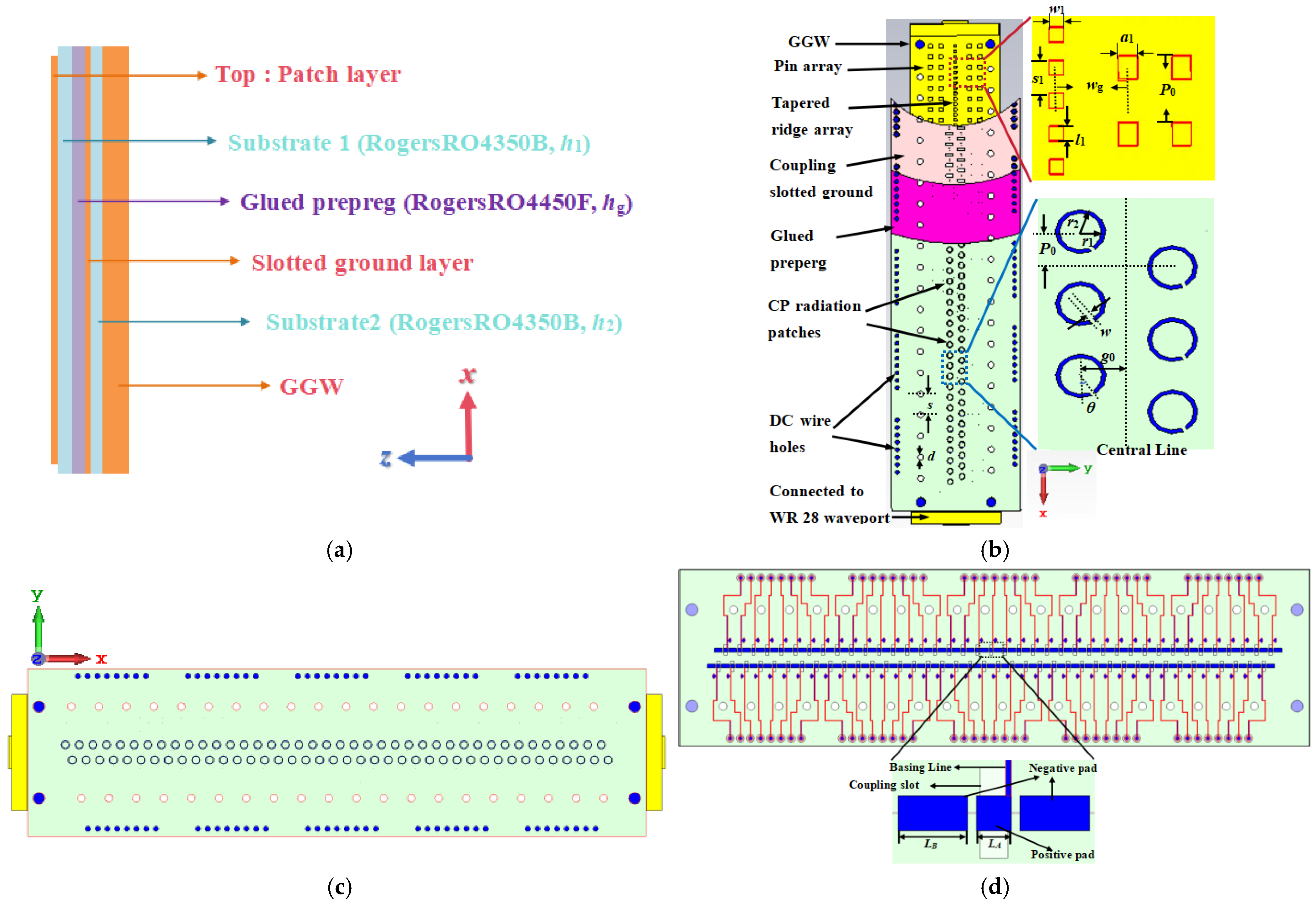
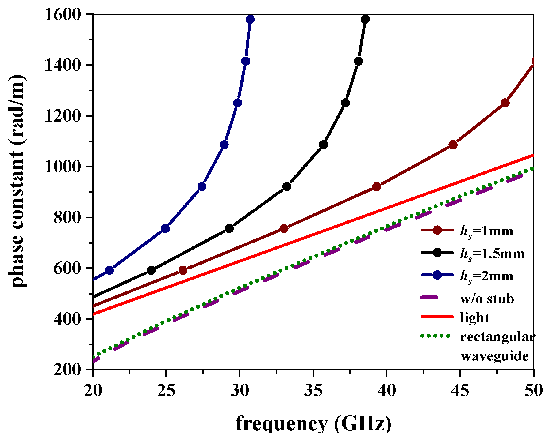
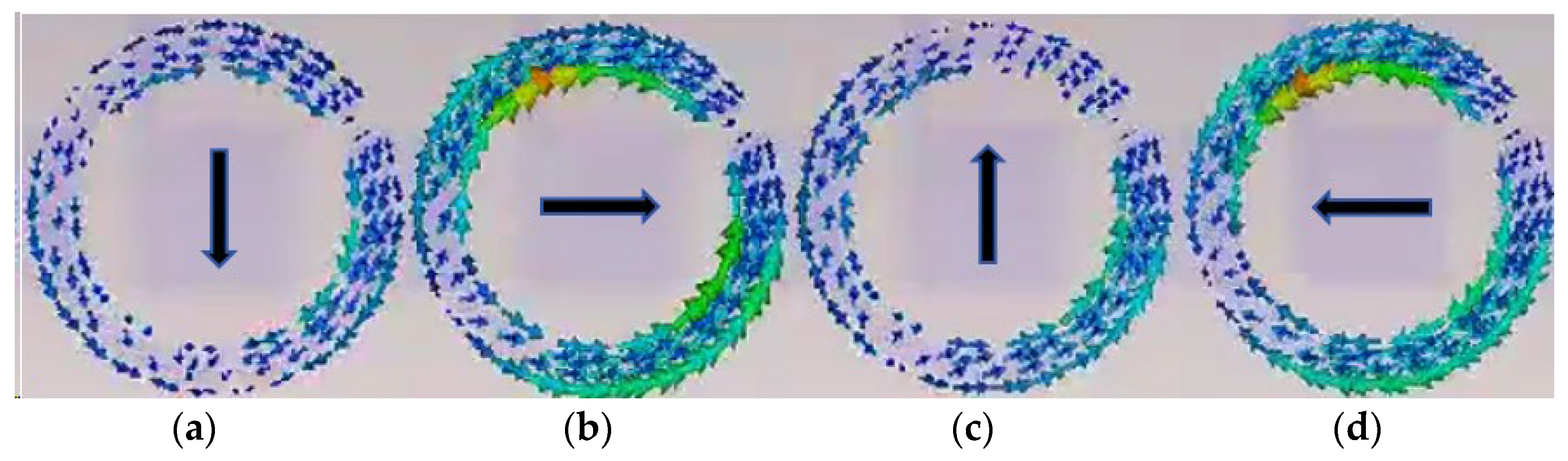
2. Configuration and Mechanism

The configuration and structural parameters of the developed antenna are given in Figure 1. The antenna has three basic layers: a bottom GGW as the transmission layer, a medium slotted ground layer for energy coupling, and a top patch layer for radiation. Additionally, a glued prepreg is used to bond the top layer and the ground layer, as shown in Figure 1a. For the bottom layer, a GGW is designed with two rows of square pin arrays on bilateral sides to form a waveguide in the Ka-band, and a tapered ridge array along the central line is used to excite a slow-wave, as shown in Figure 1b. For the top layer, a patch array with a circular split-ring-shaped unit is developed for circularly polarized radiation, as shown in Figure 1c. For the medium layer, a slotted ground with dielectric slab is designed for energy coupling from the waveguide to the patch array. A PIN diode array is arranged on the backside of the dielectric slab, to independently and electrically control the operating states of each slot and, furthermore, to reconfigure the period length of the patch array. The DC biasing network with the coupling slot is given in Figure 1d, which shows that the diodes are soldered under the slots through three pads on the back of the lower dielectric slab, with one in the center and two straddling on both sides of the slot. The bilateral rectangular pads shared by two neighboring slots are shorted to the ground layer by vias, and the central square one is used to load a biasing voltage through the biasing line with a fan-shaped choke to prevent the RF current from radiating.
In this research, for low loss and, furthermore, to achieve high gain, a GGW is chosen as the transmission structure, where two rows of square pin arrays on bilateral sides are designed to form a waveguide, and then to produce a stopband in the Ka-band. Since a fundamental fast-wave (β < k0) can only produce forward beam scanning, a slow-wave excitation should be designed for backward-to-forward beam scanning. Thus, a tapered ridge array along the central line in the GGW is then designed to suppress the fundamental wave. An important structural parameter of the stub arrays for the dispersion characteristic, height hs, is analyzed and optimized in a simulation. The dispersion curves of the GGW for different values of hs are shown in Figure 2, which demonstrate that a slow-wave property is achieved with the stub array. It is found that a larger hs will lead to a larger phase constant. Finally, hs = 1.5 mm is chosen to produce a proper slow-wave performance in the desired band. Then a fixed-frequency beam scanning with −1th spatial harmonics can be realized with periodic radiation units.
For CP radiation, a circular split-ring-shaped patch structure is properly designed and the structural parameters are optimized. As shown in Figure 3, the orientation of the surface currents features a circulation within a time period T, demonstrating a right-handed circular polarization. Thus, a RHCP LWA is achieved.
The developed CP patch array of a total of 80 units arranged in two rows on the top layer is excited by the coupling slots on the ground, and each slot is independently and electrically controlled by a pair of PIN diodes. When the PIN diode is forward biasing, the slot is shorted and then the patch is OFF, corresponding to state “0”. On the contrary, the patch works on state “1”. Thus, the period length of radiating units can be manipulated.
According to the theory of space harmonics [25], the phase constant of the nth spatial harmonics can be calculated as:
β n = β 0 + 2 π n P
where β 0 is the phase constant of the transmission TE01 mode. Then the beam angle θ n can be calculated from:
sin θ n = β n k 0 = β 0 + 2 π n / P k 0
where k0 is the wavenumber in free space. Thus, if β n < k 0 is satisfied as the radiation condition of harmonics, a fixed-frequency beam scanning can be achieved with a reconfigurable period length P.

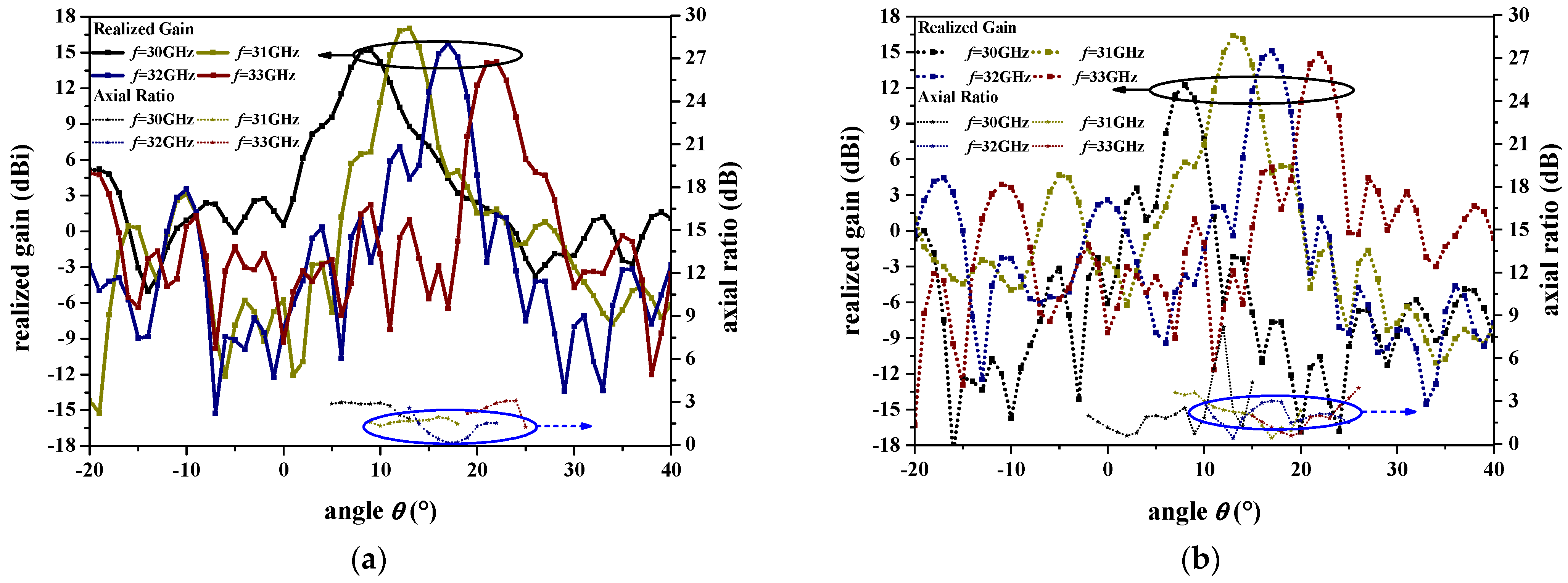
3. Simulations and Measurements

Table 1 exhibits seven operating states of the radiating patch array and its equivalent period length as well as the beam angle. With P0 of 1.75 mm, it can realize fixed-frequency beam scanning with 7 beams. The proposed antenna is simulated and optimized in the CST, and a RLC equivalent circuit is used to replace the pair of diodes in the simulation: a series circuit with R = 4.2 Ω and L = 20 pH for state “0”, and a parallel circuit with R = 300 kΩ and C = 42 fF for state “1”.
The developed antenna was fabricated and measured as shown in Figure 4.
The simulated and measured results of S-parameters of this proposed antenna are respectively shown in Figure 5a,b. For a clear exhibition, the results for only three typical states are plotted, for the backward beam, broadside beam, and forward beam. It can be seen that the developed antenna has a good performance in transmission as well as in radiation, and the measured results show a good agreement with the simulated values.
The simulated and measured results of the normalized radiation pattern for seven beams from 30 GHz to 33 GHz are respectively depicted in Figure 6a–d and Figure 7a–d. It shows that a fixed-frequency beam scanning is generated, with a range from 61° to 63° in this band, and the measured results show a good agreement.
Figure 8a,b, respectively, give the realized gains and axial ratios of state 4 for different frequencies from simulation and measurement, which indicate that good circular polarization is achieved within the main beam with a peak gain of 17.1 dBi in this band. The measured results show an agreement with an explainable gain degradation due to the machining tolerances and the uncertainty in the exact substrate permittivity.
The simulated results of radiation efficiency for three typical states are given in Figure 9a. It indicates that the radiation efficiency is mainly between −0.5 dB and −2 dB in this observation band, with an average value of −1.2 dB (87%).
To clearly illustrate the beam-scanning property of the proposed antenna, the gains and main beam directions for different beams in this observation band are given in Figure 9b. It shows that the antenna can produce fixed-frequency beam scanning with a small gain variation and a wide scanning range.
In this research, a peak gain of 17.1 dBi was achieved with a beam-scanning range of 61° as well as a good CP property. Table 2 compares the performance of the proposed beam-scanning LWA with other similar works in the open literature. It is clear to see that our work can achieve high gain featuring good beam-scanning range and CP. Overall, these developed antennas exhibit significant advantages in terms of compactness, flexibility, and high performance, but they also face challenges such as manufacturing complexity, bandwidth limitations, and cost. Future research should focus on optimizing designs, improving manufacturing processes, and reducing costs to better meet the demands of practical applications.

4. Conclusions

In this article, a circularly polarized LWA with fixed-frequency beam scanning is proposed. A GGW is firstly designed for a Ka-band transmission and a slow-wave excitation, then a periodic patch array with two rows of split-ring-shaped CP radiators is developed for a −1th spatial harmonics radiation. Each patch is independently excited by a coupling slot which is controlled by a pair of PIN diodes, generating a reconfigurable period length, and furthermore achieving a fixed-frequency beam scanning. A beam-scanning range from 61° to 63° with good CP and a peak gain of 17.1 dBi is finally realized and verified, which makes the antenna a good candidate in electronic and optical applications.

Author Contributions

Conceptualization, X.H.; methodology, X.H.; software, Y.M.; validation, X.H.; formal analysis, Q.Z.; investigation, J.L.; resources, J.L.; data curation, Q.Z.; writing—original draft preparation, X.H.; writing—review and editing, X.H.; visualization, Y.M.; supervision, X.H.; project administration, J.L.; funding acquisition, X.H. and Y.M. All authors have read and agreed to the published version of the manuscript.

Funding

This research was funded in part by the National Natural Science Foundation of China (grant no.62261034, 62401631), and in part by the Science and Technology Plan Project of Liupanshui (grant no.52020-2024-GK-02).

Institutional Review Board Statement

Not applicable.

Informed Consent Statement

Not applicable.

Data Availability Statement

Data are contained within the article.

Conflicts of Interest

The authors declare no conflicts of interest.

References

  1. Hansen, W.W. Radiating Electromagnetic Waveguide. U.S. Patent 2402622, 25 June 1946. [Google Scholar]
  2. Jackson, D.R.; Caloz, C.; Itoh, T. Leaky-wave antennas. Proc. IEEE 2012, 100, 2194–2206. [Google Scholar] [CrossRef]
  3. Sabahi, M.M.; Heidari, A.A.; Movahhedi, M. A compact CRLH circularly polarized leaky-wave antenna based on substrate-integrated waveguide. IEEE Trans. Antennas Propag. 2018, 66, 4407–4414. [Google Scholar] [CrossRef]
  4. Monticone, F.; Alu, A. Leaky-wave theory, techniques, and applications: From microwaves to visible frequencies. Proc. IEEE 2015, 103, 793–821. [Google Scholar] [CrossRef]
  5. Liu, J. Periodic leaky-wave antennas based on microstrip-fed slot array with different profile modulations for suppressing open stopband and n = −2 space harmonic. IEEE Trans. Antennas Propag. 2021, 69, 7364–7376. [Google Scholar] [CrossRef]
  6. Huo, X.; Wang, J.; Li, Z.; Li, Y.; Chen, M.; Zhang, Z. Periodic leaky-wave antenna with circular polarization and low-SLL properties. IEEE Antennas Wireless Propag. Lett. 2018, 17, 1195–1198. [Google Scholar] [CrossRef]
  7. Zhang, G.; Zhang, Q.; Chen, Y.; Murch, R.D. High-scanning-rate and wide-angle leaky-wave antennas based on glide-symmetry Goubau line. IEEE Trans. Antennas Propag. 2020, 68, 2531–2540. [Google Scholar] [CrossRef]
  8. Mishra, G.; Sharma, S.K.; Chieh, J.S. A high gain series-fed circularly polarized traveling-wave antenna at W-band using a new butterfly radiating element. IEEE Trans. Antennas Propag. 2020, 68, 7947–7957. [Google Scholar] [CrossRef]
  9. Zhao, S.; Dong, Y. Circularly polarized beam-steering microstrip leaky-wave antenna based on coplanar polarizers. IEEE Antennas Wirel. Propag. Lett. 2022, 21, 2259–2263. [Google Scholar] [CrossRef]
  10. Zhang, H.-H.; Li, R.; Ren, J.; Du, X.; Zhang, C.; Sun, X.-Y.; Yin, Y.; Shen, M. High-scanning-rate and wide-scanning-angle leakywave antenna based on double-layer slow-wave structure. IEEE Antennas Wireless Propag. Lett. 2023, 22, 2145–2149. [Google Scholar] [CrossRef]
  11. Fu, J.-H.; Li, A.; Chen, W.; Lv, B.; Wang, Z.; Li, P.; Wu, Q. An electrically controlled CRLH-inspired circularly polarized leaky-wave antenna. IEEE Antennas Wireless Propag. Lett. 2017, 16, 760–763. [Google Scholar] [CrossRef]
  12. Wang, M.; Ma, H.F.; Zhang, H.C.; Tang, W.X.; Zhang, X.R.; Cui, T.J. Frequency-fixed beam-scanning leaky-wave antenna using electronically controllable corrugated microstrip line. IEEE Trans. Antennas Propag. 2018, 66, 4449–4457. [Google Scholar] [CrossRef]
  13. Li, Z.; Guo, Y.J.; Chen, S.L.; Wang, J. A period-reconfigurable leaky-wave antenna with fixed-frequency and wide-angle beam scanning. IEEE Trans. Antennas Propag. 2019, 67, 3720–3732. [Google Scholar] [CrossRef]
  14. Geng, Y.; Wang, J.; Li, Y.; Li, Z.; Chen, M.; Zhang, Z. Radiation pattern-reconfigurable leaky-wave antenna for fixed-frequency beam steering based on substrate-integrated waveguide. IEEE Antennas Wirel. Propag. Lett. 2019, 18, 387–391. [Google Scholar] [CrossRef]
  15. Wang, S.; Li, Z.; Chen, M.; Wang, J. A TE01-mode groove-gap-waveguide-based wideband fixed-frequency beam-scanning leaky-wave antenna for millimeter-wave applications. IEEE Trans. Antennas Propag. 2021, 70, 4171–4180. [Google Scholar] [CrossRef]
  16. Liu, S.; Li, Z.; Wang, J. A fixed-frequency beam-scanning leaky-wave antenna using phase and amplitude control for millimeter-wave applications. IEEE Trans. Antennas Propag. 2022, 71, 1568–1577. [Google Scholar] [CrossRef]
  17. Wei, B.; Li, Z.; Ma, Y.; Wang, Z.; Wang, J. A Two-Dimensional Fixed-Frequency Beam-Scanning Leaky-Wave Antenna Array for Millimeter-Wave Application. IEEE Trans. Antennas Propag. 2024, 72, 4888–4899. [Google Scholar] [CrossRef]
  18. Gao, S.; Luo, Q.; Zhu, F. Circularly Polarized Antennas; Wiley: Hoboken, NJ, USA, 2013. [Google Scholar]
  19. Aljuhani, A.H.; Kanar, T.; Zihir, S.; Rebeiz, G.M. A 256-element Ku-band polarization agile SATCOM receive phased array with wide-angle scanning and high polarization purity. IEEE Trans. Microw. Theory Technol. 2021, 69, 2609–2628. [Google Scholar] [CrossRef]
  20. Kim, J.-W.; Chae, S.-C.; Jo, H.-W.; Yeo, T.-D.; Yu, J.-W. Wideband circularly polarized phased array antenna system for wide axial ratio scanning. IEEE Trans. Antennas Propag. 2022, 70, 1523–1528. [Google Scholar] [CrossRef]
  21. Wang, S.; Li, Z.; Wang, J. A Quad-Polarization Reconfigurable Fixed-Frequency Beam-Scanning Leaky-Wave Antenna Based on the Holographic Method for Millimeter-Wave Application. IEEE Trans. Antennas Propag. 2023, 71, 723–733. [Google Scholar] [CrossRef]
  22. Dimitrov, K.C.; Lee, Y.; Min, B.-W.; Park, J.; Jeong, J.; Kim, H.-J. Circularly polarized T-shaped slot waveguide array antenna for satellite communications. IEEE Antennas Wireless Propag. Lett. 2020, 19, 317–321. [Google Scholar] [CrossRef]
  23. Agarwal, R.; Yadava, R.L.; Das, S. A multilayered SIW-based circularly polarized CRLH leaky wave antenna. IEEE Trans. Antennas Propag. 2021, 69, 6312–6321. [Google Scholar] [CrossRef]
  24. Mallioras, I.; Zaharis, Z.D.; Lazaridis, P.I.; Pantelopoulos, S. A novel realistic approach of adaptive beamforming based on deep neural networks. IEEE Trans. Antennas Propag. 2022, 70, 8833–8848. [Google Scholar] [CrossRef]
  25. Geng, Y.; Wang, J.; Li, Z.; Li, Y.; Chen, M.; Zhang, Z. A compact circularly polarized half-mode substrate integrated waveguide-based leaky-wave antenna array with wide range of dual-beam scanning. Int. J. RF Microw. Comput. Aided Eng. 2022, 32, e23074. [Google Scholar] [CrossRef]
  26. Cheng, Y.J.; Hong, W.; Wu, K. Millimeter-wave half mode substrate integrated waveguide frequency scanning antenna with quadri-polarization. IEEE Trans. Antennas Propag. 2010, 58, 1848–1855. [Google Scholar] [CrossRef]
  27. Liao, Q.; Wang, L. Switchable bidirectional/unidirectional LWA array based on half-mode substrate integrated waveguide. IEEE Antennas Wirel. Propag. Lett. 2020, 19, 1261–1265. [Google Scholar] [CrossRef]
  28. Geng, Y.; Wang, J.; Li, Y.; Li, Z.; Chen, M.; Zhang, Z. A Ka-band leaky-wave antenna array with stable gains based on HMSIW structure. IEEE Antennas Wirel. Propag. Lett. 2022, 21, 1597–1601. [Google Scholar] [CrossRef]
  29. Liu, Y.Q.; Zhu, Y.; Wang, Y.; Ren, Z.; Yin, H.; Qi, K.; Sun, J. Monolithically integrated wide field-of-view metalens by angular dispersionless metasurface. Mater. Des. 2024, 240, 112879. [Google Scholar] [CrossRef]
Figure 1. Configuration and parameters of the CP FFBS LWA. (a) Side view; (b) perspective view; (c) top view; (d) DC biasing network and detailed structure. Dimensions (mm): r2 = 1.1, r1 = 0.92, w = 0.2, g0 = 4, P0 = 1.75, LA = 1, LB = 2, d = 1, s = 6, a1 = 1.6, wg = 4, w1 = 1, s1 = 1.8 h1 = 0.762, h2 = 0.254, hg = 0.101, and l1= 0.8.
Photonics 12 00274 g001
Figure 2. Dispersion diagram of the GGW with and without the ridge array.
Photonics 12 00274 g002
Figure 3. Surface currents on the patch within a time period T. (a) t = 0. (b) t = T/4. (c) t = 2T/4. (d) t = 3T/4.
Photonics 12 00274 g003
Figure 4. Photographs of the fabricated antenna in measurement.
Photonics 12 00274 g004
Figure 5. Results of reflection and transmission coefficients from (a) simulation and (b) measurement.
Photonics 12 00274 g005
Figure 6. Results of the normalized radiation pattern of all the states from simulation for (a) 30 GHz, (b) 31 GHz, (c) 32 GHz, and (d) 33 GHz.
Photonics 12 00274 g006
Figure 7. Results of the normalized radiation pattern of all the states from measurement for (a) 30 GHz, (b) 31 GHz, (c) 32 GHz, and (d) 33 GHz.
Photonics 12 00274 g007
Figure 8. Results of the realized gain and axial ratio of state for 4 different frequencies, respectively, from (a) simulation and (b) measurement.
Photonics 12 00274 g008
Figure 9. Simulated results of (a) radiation efficiency and (b) realized gains and main beam directions.
Photonics 12 00274 g009
Table 1. Operation states of patch array.
NOperation StatesPeriod Lengthθn
110010010010010010010010010010010010010010010010010010010010010010010010010010010P = 3P0−13°
211001100110011001100110011001100110011001100110011001100110011001100110011001100P = 4P0−8°
311001100011000110001100110001100011000110011000110001100011001100011000110001100P = 4.75P0
411000110001100011000110001100011000110001100011000110001100011000110001100011000P = 5P013°
511100011100001110001110000111000111000011100011100001110001110000111000111000011P = 6.5P021°
611110000111100001111000011110000111100001111000011110000111100001111000011110000P = 8P032°
711111100000011111100000011111100000011111100000011111100000011111100000011111100P = 12P048°
Table 2. Comparison of the proposed antenna with other similar works.
Ref.Frequency (GHz)Bean-Scanning RangePeak Gain
(dBi)
Polarization
[25]5.2–6.9−62° to 0°13.5Circular polarization
[26]33–39−30° to 3°14.85Quadri-polarization
[27]12–14−30° to 59°15.95Linear polarization
[28]27–40−40° to 30°15Linear polarization
[29]9.5−40° to 40°-Single polarization
This work26–38−13° to 48°17.1Circular polarization
Disclaimer/Publisher’s Note: The statements, opinions and data contained in all publications are solely those of the individual author(s) and contributor(s) and not of MDPI and/or the editor(s). MDPI and/or the editor(s) disclaim responsibility for any injury to people or property resulting from any ideas, methods, instructions or products referred to in the content.

