Article

Spatial Goos–Hänchen Shifts of Airy Vortex Beams Impinging on Graphene/hBN Heterostructure

1
School of Science, Xi’an Shiyou University, Xi’an 710065, China
2
School of Electronic Engineering, Xidian University, Xi’an 710071, China
3
School of Physics, Xidian University, Xi’an 710071, China
*
Authors to whom correspondence should be addressed.
Photonics 2025, 12(2), 105; https://doi.org/10.3390/photonics12020105
Submission received: 25 November 2024 / Revised: 27 December 2024 / Accepted: 22 January 2025 / Published: 24 January 2025

Abstract

:
Based on the angular spectrum expansion, the spatial Goos–Hänchen (GH) shift of an Airy vortex beam reflected from the graphene/hexagonal boron nitride (hBN) heterostructure is investigated analytically. The influences of graphene/hBN heterostructure parameters and incident Airy vortex beam parameters on the spatial GH shifts are analyzed in detail. It is found that the position of the Brewster angle mainly depends on the relaxation time and hBN thickness of the heterostructure, and the magnitude and sign of GH shifts at a certain Brewster angle can be controlled effectively by tuning the Fermi energy and layer numbers of graphene. Moreover, the variation in the GH shifts with the Fermi energy and hBN thickness exhibits hyperbolicity at the Brewster angle, similar to the variation in the permittivity of hBN. For the incident beam, the vortex position and the decay factor in the x direction have a great effect on the GH shifts. The influence of the vortex position on the GH shift is related to the distance of the vortex position from the origin point. The magnitude of the GH shift decreases as the decay factor in the x direction increases, and a large GH shift can be obtained by adjusting the decay factor in the x direction. Finally, the application of spatial GH shift in sensing is discussed. The results presented here may provide some supports to the design of optical switch and optical sensor.

1. Introduction

Airy beams [1] represent the first experimentally observed class of self-accelerating optical waves [2] whose intensity features follow a curved parabolic trajectory [3,4], and possess diffraction-free [5] and self-healing [6] properties. The amplitude profiles of the Airy beams remain invariant in the transverse plane during propagation [3,4]. At the same time, the Airy beams tend to reform or reconstruct themselves even when they have been severely perturbed or distorted [7]. Owing to the fascinating properties, Airy beams have been utilized in a variety of applications, including optical micromanipulation [8,9,10], curved plasma channel generation [11,12], vacuum electron acceleration [13], and surface plasmon polariton [14,15]. Vortex beams carry orbital angular momentum (OAM) and have helical wavefronts and phase singularities, which have broad applications in optical trapping [16,17], optical communication [18,19], and optical metrology and quantum information [20]. The Airy vortex beams can be generated by placing a spiral phase plate at the Fourier plane of the cubic phase mask [21,22]. Since the Airy vortex beams not only maintain the excellent properties of Airy beams, but also possess phase singularities and OAM, studies on the Airy vortex beams are becoming hotspots recently [23,24,25].
Graphene, a novel 2D material composed of carbon atoms in a honeycomb-like structure, exhibits unique optical properties, including broadband, electrical tunability, and high electron mobility [26,27]. More importantly, the Fermi energy of graphene can be adjusted dynamically by changing the external gate voltage or the impurity concentration without altering the structure. Hexagonal boron nitride (hBN), a natural hyperbolic material with a similar structure to graphene, can be used as an excellent substrate for graphene devices as it is insulating, atomically flat, and provides a clean charge environment for the graphene [28,29]. Meanwhile, graphene on hBN substrate can maintain the intrinsic properties [30]. So, the graphene/hBN heterostructure has both hyperbolic and tunable characteristics [31]. Characterization of graphene on hBN devices can be realized by infrared nano-spectroscopy and nano-imaging via a scattering-type scanning near-field optical microscope [28,31]. The graphene/hBN heterostructure can enable plentiful phononic and plasmonic resonance modes, of which surface plasmon–phonon polaritons modes [32] that originate from the coupling between surface plasmons in graphene and phonon polaritons in hBN greatly enhance the photon tunneling [33]. The tunable, omnidirectional, and nearly perfect absorptions and the tunable multi-wavelength absorptions were achieved at infrared frequencies by using the different graphene/hBN heterostructures [34,35,36]. The graphene/hBN heterostructure enables flexible switching of reflected group delay through the Lorentz resonance mechanism [37]. The graphene/hBN heterostructures have broad application prospects in infrared technology and nanophotonics.
In geometrical optics, it is widely recognized that the reflection and refraction of a plane wave on an interface are described by the Snell’s law and Fresnel formulas [38]. However, for a real optical beam with finite width, nonspecular reflection phenomena will occur, such as Goos–Hänchen (GH) [39] and Imbert–Fedorov (IF) [40] shifts, the former occurring in the plane of incidence, while the latter occurs in the plane perpendicular to it. An overview on the GH and IF beam shifts can be found in reference [41]. Because any beams of arbitrary shape can be decomposed into plane waves, the beam shifts for different incident beams, such as Gaussian beams [42,43,44,45], Laguerre–Gaussian beams [46,47], Hermite–Gauss beams [48], Bessel beams [49], and Airy beams [24,50,51,52,53], have been studied employing the angular spectrum expansion theory. Meanwhile, there have been many intriguing structures as reflection interfaces to flexibly control and enhance beam shifts as well, such as photonic crystals [54,55], weakly absorbing media [24,51], negative refractive media [56], anisotropic medium interface [57], graphene [52,58,59], epsilon-near-zero metamaterials [53,60], semiconductor structure [61], guided-surface plasmon resonance structure [62], and metasurfaces [43,63,64]. However, the beam shifts have the same order of magnitude as the incident wavelength, which is difficult to be directly observed. By using the weak measurement technique, the beam shifts can be enhanced effectively, and thus observed [65,66]. Thus, the beam shifts have been used in sensing [67,68], precision measurement [69,70], and optical differential operation and image edge detection [71].
For the case of Airy beams, Pedro numerically analyzed the GH shifts of an Airy beam incident on a nonlinear interface using the nonlinear Helmholtz equation [72]. Employing the angular spectrum expansion theory, Ornigotti presented a complete analytical theory of GH and IF shifts for Airy beams impinging upon a dielectric surface [50], and Zhai presented that the Airy beam experiences nonzero GH shift when it is perpendicularly incident on the interface between air and epsilon-near-zero metamaterial [53]. In the same way, Deng investigated the GH and IF shifts of rotational Airy beams [51] and off-axis Airy vortex beams [24] at the surface between air and weakly absorbing medium. Meanwhile, Deng also discussed the GH shifts for Airy beams impinging upon a weakly absorbing medium surface coated with the monolayer graphene [52], and the GH shifts can be enhanced in the graphene substrate surfaces. Song investigated the large spatial shifts of a reflective Airy beam impinging upon the surface of hyperbolic crystals [73]. From the above research, it follows that various media as reflection interfaces have different influences on the beam shifts. By comparing Laguerre–Gaussian beams, Bessel beams, and Airy vortex beams, we found that the topological charges affect the GH shifts of vortex beams. Additionally, for Airy vortex beams, the decay parameter, axial symmetry of the initial field, and vortex position also have huge influences on the GH shifts. Graphene/hBN heterostructure as a tunable hyperbolic metamaterial has excellent optical properties. Fan proposed that a tunable GH shift can be realized using electrically controllable graphene in the terahertz regime [74,75]. Song investigated the spatial shifts of a Gaussian beam reflected from the surface of graphene/hBN metamaterials by effective medium method in the THz region [76]. Zheng proposed a bimetal structure based on graphene–hBN to enhance the GH shift in infrared band [77]. Zhao analyzed the GH shift of trapezoidal dielectric hBN grating structure [78]. However, these studies focused on the spatial shifts of foundational plane waves and Gaussian beams. Here, employing the angular spectrum expansion theory and the transfer matrix method, the GH shifts of more complicated Airy vortex beams in the infrared region impinging on graphene/hBN heterostructure are investigated to realize the control of the GH shifts from heterostructure parameters and incident beam parameters. Meanwhile, the surface conductivity of graphene in the infrared region exhibits different properties compared to the visible light region, thus the tunability of GH shifts based on graphene/hBN heterostructure will also be different. The study of GH shifts for Airy vortex beams impinging on graphene/hBN heterostructure is valuable for exploring some novel and interesting results.
In this paper, the spatial GH shift of an Airy vortex beam impinging on graphene/hBN heterostructure is investigated analytically. Based on the angular spectrum expansion, the analytical expression of the spatial GH shift for an Airy vortex beam incident on the graphene/hBN heterostructure is derived in Section 2. In Section 3, the influences of graphene/hBN heterostructure parameters (including Fermi energy, relaxation time, layer numbers of graphene, and hBN thickness) and incident Airy vortex beam parameters (including vortex position and decay factor) on the spatial GH shifts are analyzed. Meanwhile, the application of spatial GH shift in sensing is also presented. Finally, the paper is concluded in Section 4.

2. Theoretical Formulation

Consider a monochromatic Airy vortex beam incident upon a graphene/hBN heterostructure that is placed on a SiO2 substrate, as shown in Figure 1. The laboratory coordinate system ( x , y , z ) is established at the graphene interface, ( x i , y i , z i ) and ( x r , y r , z r ) represent the incident and the reflected coordinate system, correspondingly. The incident angle is θ . ε 1 = 1 and ε 3 = 3.9 denote the relative permittivity of air and SiO2 substrate, respectively. According to the Kubo formalisms [79,80], the surface conductivity of graphene can be written as the sum of intra-band and inter-band terms. However, the inter-band conductivity can be neglected at the infrared region, so the conductivity σ of monolayer graphene can be expressed as
σ = i e 2 E f π 2 ( ω + i / τ )
where ω is the angular frequency of the incident beam, is the Planck constant, e is the electron charge, τ is the relaxation time, and E f is the Fermi energy of graphene. N is the layer numbers of graphene. For N 6 , the conductivity of multi-layer graphene meets the linear relationship [26,81]
σ t o t a l = N σ .
hBN is a natural hyperbolic material with two kinds of phonon modes in the infrared (IR): in-plane E 1 U phonon modes ( ω T O , 1 = 1370   cm 1 , ω L O , 1 = 1610   cm 1 ) and A 2 U out-of-plane phonon modes ( ω T O , 2 = 780   cm 1 , ω L O , 2 = 830   cm 1 ), which lead to two distinct Reststrahlen (RS) bands. The lower-frequency RS band corresponds to type-I hyperbolicity ( ε x = ε y > 0 , ε z < 0 ), and the higher-frequency RS band corresponds to type-II hyperbolicity ( ε x = ε y < 0 , ε z > 0 ). The permittivity of hBN can be expressed as [29,37]
ε u = ε , u ( 1 + ω L O , 1 2 ω T O , 1 2 ω T O , 1 2 ω 2 i ω γ u )
ε z = ε , z ( 1 + ω L O , 2 2 ω T O , 2 2 ω T O , 2 2 ω 2 i ω γ z )
where u = x , y represents the transverse direction (a, b crystal plane) and z represents the z -axis direction (lattice c-axis). ε and γ represent high-frequency permittivity and attenuation constant, respectively, ε , x = ε , y = 4.87 , γ x = γ y = 5   cm 1 , ε , z = 2.95 , and γ z = 4   cm 1 .
Based on the angular spectrum expansion, the incident and reflected electric field at the position r μ = x μ x ^ μ + y μ y ^ μ + z μ z ^ μ can be expressed as:
E μ ( r μ ) = 1 2 π E ˜ μ ( r μ ) e i ( k μ r μ ) d k x μ k y μ
where the subscript μ = i , r denotes the incident or the reflected coordinate system. The incident wave vector can be expressed as k i = k x i x ^ i + k y i y ^ i + k z i z ^ i . Meanwhile, let k x i = k 1 U , k y i = k 1 V , k z i = k 1 W , and W = ( 1 U 2 V 2 ) 1 / 2 , where k 1 = k i = 2 π / λ 0 with the wavelength λ 0 of the incident beams. According to the geometrical relationship law k r = k i 2 z ^ ( z ^ k i ) between k i and k r , k r = k 1 U x ^ r + k 1 V y ^ r + k 1 W z ^ r . Moreover, we define X μ = k 1 x μ , Y μ = k 1 y μ , Z μ = k 1 z μ . The angular spectra of the incident and reflected electric field can be written as follows [42]:
E ˜ μ ( r μ ) = λ p , s e ^ λ ( k μ ) α λ ( U , V ; θ ) A ˜ μ ( U , V ; θ )
where λ = p , s denotes p or s polarization. The polarization unit basis vectors e ^ λ ( k μ ) can be characterized by e ^ p ( k μ ) = ( e ^ s ( k μ ) × k μ ) / e ^ s ( k μ ) × k μ and e ^ s ( k μ ) = ( z ^ × k μ ) / z ^ × k μ . The polarized vector spectral amplitudes α λ ( U , V ; θ ) = e ^ λ ( k i ) f ^ , where f ^ = f p x ^ i + f s y ^ i ( f p 2 + f s 2 = 1 ) describes the polarization state of the beam in the incident frame, and f p = a p , f s = a s e i η . A ˜ i ( U , V ; θ ) = A ˜ ( U , V ) is the angular spectrum of the incident field, and A ˜ r ( U , V ; θ ) = r λ ( U , V ; θ ) A ˜ ( U , V ; Z i 0 ) is the angular spectrum of the initial reflected field, where Z i 0 is the transmission distance before reflecting along z ^ i . r λ ( U , V ; θ ) is the Fresnel reflection coefficient. Because the decay factors of the Airy vortex beams adopted in this paper are greater than the order of 10−2, first order Taylor expansion of the Fresnel reflection coefficient at U = 0 and V = 0 is enough [51]. The Fresnel reflection coefficients can be expressed as follows:
r λ ( U , V ; θ ) r λ ( θ ) + U r λ ( θ )
here r λ ( θ ) = R λ e i φ λ is the ordinary reflection coefficient, and r λ ( θ ) is the first order differential of the ordinary reflection coefficient to the incident angle θ . The initial amplitude of the Airy vortex beam has the following form [24]:
A ( x , y ) = Ai ( x w 0 ) Ai ( y w 0 ) exp ( α x w 0 + β y w 0 ) ( x x 0 w 0 + i y y 0 w 0 ) l
where Ai ( ) is the Airy function, w 0 is the beam width, and α and β are the decay factors of the Airy part along with x and y directions separately. x 0 and y 0 separately refer to the dislocation of the optical vortex from the origin in the x and y axes, and l is the topological charge of the vortex. For l = 1 , the spectral amplitude of the Airy vortex beam can be expressed as follows:
A ˜ ( U , V ) = A ˜ 0 ( U , V ) P A ˜ 0 ( U , V ) = w 0 2 exp ( α 3 + β 3 3 ) exp ( α U 2 + β V 2 ϑ 2 ) exp [ i ( U 3 + V 3 3 ϑ 3 α 2 U + β 2 V ϑ ) ] P = { [ ( α i U ϑ ) 2 x 0 w 0 ] + i [ ( β i V ϑ ) 2 y 0 w 0 ] }
where ϑ = 1 / k 1 w 0 . A ˜ 0 ( U , V ) is the angular spectrum of 2-D finite energy Airy beams, and P denotes the angular spectrum of the vortex term. The angular spectra of the incident and reflected Airy vortex beam can be written as:
E ˜ i ( r i ) = A I ( k 1 ) A ˜ ( U , V ) = [ e ^ p ( k i ) α p ( U , V ; θ ) + e ^ s ( k i ) α s ( U , V ; θ ) ] A ˜ ( U , V ) E ˜ r ( r r ) = A R ( k 1 ) A ˜ ( U , V ) = [ e ^ p ( k r ) α p ( U , V ; θ ) + e ^ s ( k r ) α s ( U , V ; θ ) ] r λ ( U , V ; θ ) A ˜ ( U , V ) .
Let
N R = E ˜ r 2 d U d V = + | A R ( k 1 ) | 2 | A ˜ ( U , V ) | 2 d U d V M R = Im [ E ˜ r U E ˜ r ] d U d V = Im + { A R ( k 1 ) U A R ( k 1 ) | A ˜ ( U , V ) | 2 + | A R ( k 1 ) | 2 A ˜ ( U , V ) U A ˜ ( U , V ) } d U d V
N I = E ˜ i 2 d U d V = + | A I ( k 1 ) | 2 | A ˜ ( U , V ) | 2 d U d V M I = Im [ E ˜ i U E ˜ i ] d U d V = Im + { A I ( k 1 ) U A I ( k 1 ) | A ˜ ( U , V ) | 2 + | A I ( k 1 ) | 2 A ˜ ( U , V ) U A ˜ ( U , V ) } d U d V .
According to the definition of the GH shift in references [42,51], the spatial GH shift of the Airy vortex beam can be expressed as follows:
k 1 Δ GH = Im [ E ˜ r U E ˜ r ] d U d V E ˜ r 2 d U d V Im [ E ˜ i U E ˜ i ] d U d V E ˜ i 2 d U d V = M R N R M I N I
where
N I = N I 0 + N I 1 M I = L I 1 + L I 2 + L I 3 + L I 4 N R = N R 0 + N R 1 M R = L R 1 + L R 2 + L R 3 + L R 4
N I 0 = P c 2 Q I N R 0 = P c 2 Q R 1 N I 1 = p 0 N R 1 = p 0 ( a p 2 R p 2 + a s 2 R s 2 ) + p 1 p 2 + p 3 a p ( 2 a s cos η ) cot θ ( R p 2 R s 2 ) L I 1 = 0   L R 1 = P c 2 Q R 2 L I 2 = ( a p a s sin η ) p 3     L R 2 = p 0 ( a p 2 R p 2 φ p + a s 2 R s 2 φ s ) + p 3 p 4 L I 3 = P c 2 T u 2 / ϑ 3 N I   α 2 / ϑ L R 3 = ( a p 2 R p 2 + a s 2 R s 2 ) P c 2 T u 2 / ϑ 3 N R α 2 / ϑ  
L I 4 = p 5 Q I 2 α T u 2 / ϑ 3 L R 4 = p 5 Q R 1 ( a p 2 R p 2 + a s 2 R s 2 ) 2 α T u 2 / ϑ 3 + 2 ( β 2 y 0 / w 0 ) p 2 T u 2 / ϑ 2     4 α β ( R p 2 R s 2 ) a p ( 2 a s cos η ) cot θ T v 2 / ϑ 2
where P c 2 = α 4 + ( x 0 / w 0 ) 2 2 α 2 x 0 / w 0 + β 4 + ( y 0 / w 0 ) 2 2 β 2 y 0 / w 0 is the constant term of P 2 , and T = | A ˜ 0 ( U , V ) | 2 d U d V = w 0 4 exp [ 2 ( α 3 + β 3 ) / 3 ] π ϑ 2 / ( 2 α β ) , T u 2 = U 2 | A ˜ 0 ( U , V ) | 2 d U d V = T ϑ 2 / 4 α , T v 2 = V 2 | A ˜ 0 ( U , V ) | 2 d U d V = T ϑ 2 / 4 β . Other related parameters can be expressed as follows:
p 0 = [ ( 2 α 2 + 2 x 0 w 0 ) T u 2 ϑ 2 + ( 2 β 2 + 2 y 0 w 0 ) T v 2 ϑ 2 ] p 1 = ( 4 α y 0 w 0 4 α β 2 ) T u 2 ϑ p 2 = 2 [ a p 2 Re ( r p r p ) + a s 2 Re ( r s r s ) ] p 3 = ( 4 α 2 β 4 β x 0 w 0 ) T v 2 ϑ p 4 = [ a p ( 2 a s cos η ) cot θ ( R p 2 φ p R s 2 φ s ) + a p a s sin η Im ( r p r s ) ] p 5 = ( 2 α 3 ϑ + 2 α ϑ x 0 w 0 )
Q R 1 = T ( a p 2 R p 2 + a s 2 R s 2 ) + T u 2 a p 2 R p 2 + T v 2 a s 2 R s 2       + T u 2 ( a p 2 r p 2 + a s 2 r s 2 ) + T v 2 ( R p 2 cot 2 θ + R s 2 cot 2 θ ) Q R 2 = T ( a p 2 R p 2 φ p + a s 2 R s 2 φ s ) + T u 2 a p 2 R p 2 φ p + T v 2 a s 2 R s 2 φ s       + T v 2 cot 2 θ ( R p 2 φ p + R s 2 φ s ) Im ( r p r s ) ( a s 2 a p 2 ) T v 2 cot θ Q I = T + T v 2 2 cot 2 θ + T u 2 a p 2 + T v 2 a s 2 .
When the topological charge l = 0 in Equation (8), A ( x , y ) denotes the initial amplitude of the Airy beam, and the spectral amplitude of the Airy beam is A ˜ ( U , V ) = A ˜ 0 ( U , V ) . By substituting A ˜ ( U , V ) = A ˜ 0 ( U , V ) into Equations (10)–(13), the GH shift for the Airy beam is obtained, which is consistent with the result Δ GH ( A i r y ) = Δ GH ( g ) Γ in reference [50]. Therefore, the correctness of the method provided in this paper can be verified.
The transmission matrix method (TMM) is used to calculate the Fresnel reflection coefficient of the Airy vortex beam incident from air to the graphene/hBN heterostructure [37,82]. The transmission matrix D λ , 1 2 ( λ = p , s   ) from air to hBN can be expressed as
D p , 1 2 = 1 2 1 + η p , 1 2 + ξ p , 1 2 1 η p , 1 2 ξ p , 1 2 1 η p , 1 2 + ξ p , 1 2 1 + η p , 1 2 ξ p , 1 2
for p polarization, η p , 1 2 = k 2 z ε 1 / k 1 z ε x ,   ξ p , 1 2 = σ k 2 z / ε 0 ε x ω ; and
D s , 1 2 = 1 2 1 + η s , 1 2 + ξ s , 1 2 1 η s , 1 2 + ξ s , 1 2 1 η s , 1 2 ξ s , 1 2 1 + η s , 1 2 ξ s , 1 2
for s polarization, η s , 1 2 = k 2 z / k 1 z ,   ξ s , 1 2 = σ μ 0 ω / k 1 z ; ε 0 and μ 0 are the permittivity and permeability in vacuum, respectively. k 0 = ω / c denotes the wave vector in a vacuum. k x = ε 1 k 0 sin θ is the wave vector component of the incident beam in the x direction in the air. k 1 z = ε 1 k 0 cos θ , k 2 z = ε x k 0 2 ε x k x 2 / ε z , and k 3 z = ε 3 k 0 2 k x 2 are the wave vector component of the beam in the z direction in the air, hBN, and SiO2 substrate, respectively. The propagate matrix of the beam in the hBN can be expressed as
P = 1 2 exp ( i k 2 z d h B N ) 0 0 exp ( i k 2 z d h B N )
where d h B N is the thickness of hBN. The transmission matrix D λ , 2 3 from hBN to SiO2 substrate can be written as
D p , 2 3 = 1 2 1 + η p , 2 3 1 η p , 2 3 1 η p , 2 3 1 + η p , 2 3
D s , 2 3 = 1 2 1 + η s , 2 3 1 η s , 2 3 1 η s , 2 3 1 + η s , 2 3
where η p , 2 3 = ε x k 3 z / ε 3 k 2 z and η s , 2 3 = k 3 z / k 2 z . The transfer matrix of the graphene/hBN heterostructure can be written as
M λ = D λ , 1 2 P D λ , 2 3 .
Hence, the Fresnel reflection coefficients of the graphene/hBN heterostructure can be derived as
r λ = M λ , 21 / M λ , 11 .
By substituting Equation (25) into Equation (7) and performing the algebraic manipulations in Equations (10)–(13), the expression for the GH shift of the Airy vortex beam impinging on the graphene/hBN heterostructure is obtained.

3. Results

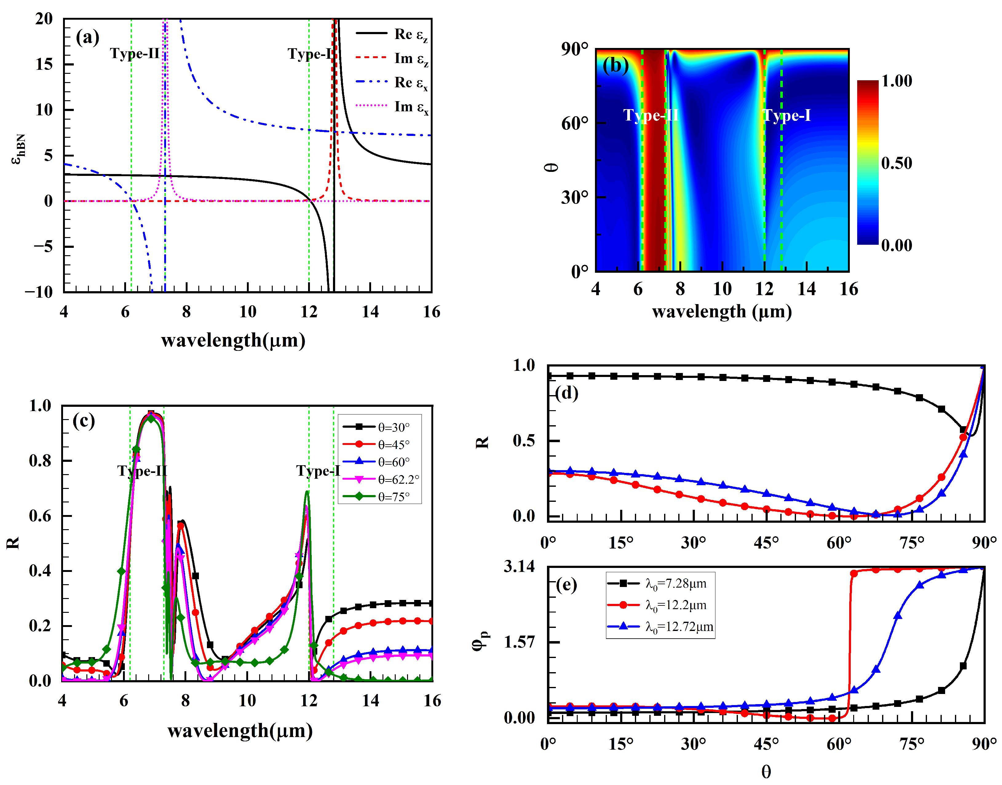
In the following discussion, we only consider the p-polarized Airy vortex beam. The real and imaginary parts of the permittivity of hBN are shown in Figure 2a. Near λ 0 = 7.28   μ m and λ 0 = 12.72   μ m , the real part of the permittivity from negative value jump to a positive value and the imaginary part of the permittivity has a large positive value, since hBN has Lorentz resonance characteristics near these wavelengths. It is known that the reflection phase mutation occurs at the minimum reflectance, thereby causing a large GH shift [77]. The greater the slope d φ p / d θ , the larger the absolute value of the GH shift [58]. In order to obtain the appropriate wavelength and incident angle to enhance the GH shift, the reflectance of the graphene/hBN heterostructure with a different wavelength and incident angle is simulated in Figure 2b,c, and the parameters of the heterostructure are E f = 0.2   eV , N = 1 , τ = 500   fs , and d h B N = 1.55   μ m . In the type-I region, the reflectance of the graphene/hBN heterostructure has a minimum at λ 0 = 12.2   μ m , and the permittivity of hBN satisfies the Lorentz resonance characteristics at this wavelength, so λ 0 = 12.2   μ m is selected as the incident wavelength. Figure 2d,e shows the variation in reflectance and reflection phase with incident angle θ at λ 0 = 7.28   μ m ,   12.2   μ m   and   12.72   μ m , respectively. For λ 0 = 12.2   μ m , the reflectance reaches the minimum and the slope of the reflection phase on the incident angle is the greatest at incident angle θ = 62.2 ° . Therefore, a larger GH shift is obtained at incident wavelength λ 0 = 12.2   μ m and incident angle θ = 62.2 ° .

3.1. Effects of Graphene/hBN Heterostructure Parameters

In this section, we study the influences of graphene/hBN heterostructure parameters on the spatial GH shifts. The parameters of the incident Airy vortex beam are set to w 0 = 1   mm , α = β = 0.1 , and x 0 = y 0 = 0   m . In general, the angle that corresponds to the maximum value of the GH shift is named as Brewster angle θ B .
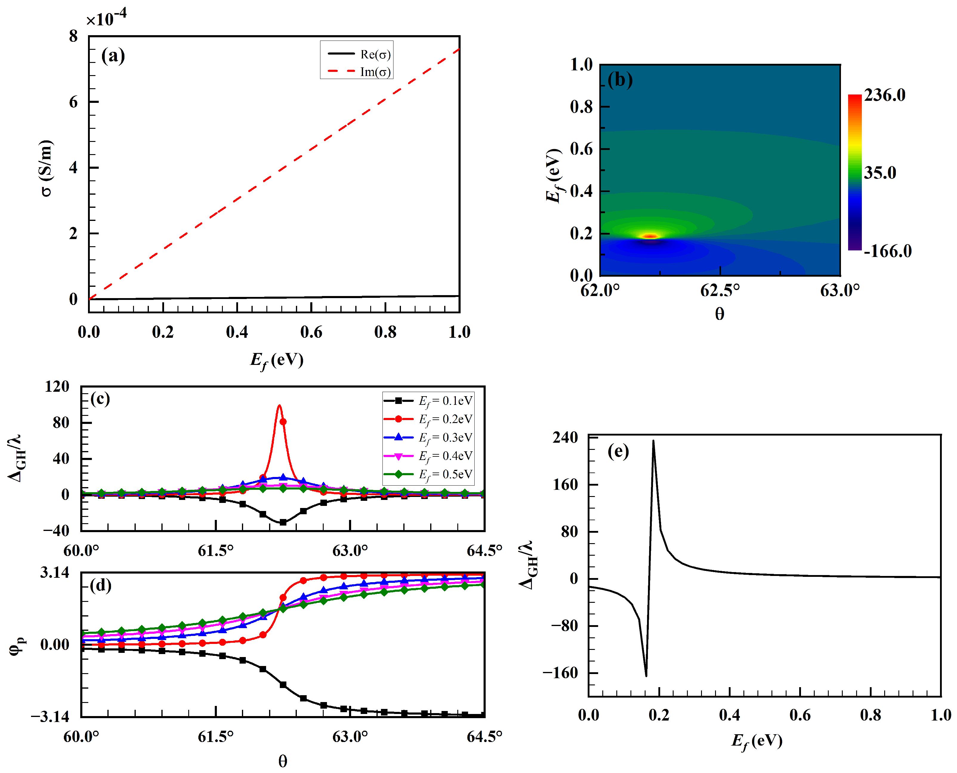
Figure 3a exhibits the real and imaginary parts of monolayer graphene conductivity as a function of Fermi energy E f . As shown in Figure 3a, the imaginary part of the graphene conductivity is much greater than the real part. As the Fermi energy increases, the imaginary part of the graphene conductivity increases; however, the real part of the graphene conductivity hardly changes. The position of Brewster angle is closely related to the real part of the graphene conductivity, and the magnitude and sign of GH shifts are closely related to the imaginary part of the graphene conductivity [58]. Figure 3b depicts a pseudo-color image of the GH shifts with different Fermi energy E f and incident angle θ . Figure 3c,d shows the dependence of the GH shifts and reflection phase φ p on the incident angle θ for different Fermi energy E f separately. From Figure 3b,c, we can find that the larger GH shifts appear near the Brewster angle θ = 62.2 ° , and the position of the Brewster angle keeps invariable because the real part of the graphene conductivity does not change with Fermi energy. Since the imaginary part of the graphene conductivity varies with the Fermi energy, the Fermi energy will affect the magnitude and sign of GH shifts, and the results are illustrated in Figure 3b,c. The GH shifts remain positive at E f > 0.17   eV . Meanwhile, the magnitude and sign of the GH shifts are related to the slope of the reflection phase on the incident angle. As shown in Figure 3c,d, the larger the slope of the reflection phase is, the larger the absolute value of the GH shift will be. Figure 3e depicts the variation in the GH shifts with the Fermi energy E f at the Brewster angle. The variation in the GH shifts with the Fermi energy is hyperbolic, which is similar to the variation in the permittivity of hBN. The GH shifts jump from negative maximum value to positive maximum value when the Fermi energy increases from 0.16   eV to 0.2   eV . The GH shift reaches up to 235 λ at Fermi energy E f = 0.18   eV , significantly larger than that obtained in the bimetal structure based on graphene–hBN [77]. The positive and negative switching of GH shifts can be realized easily by tuning the Fermi energy.
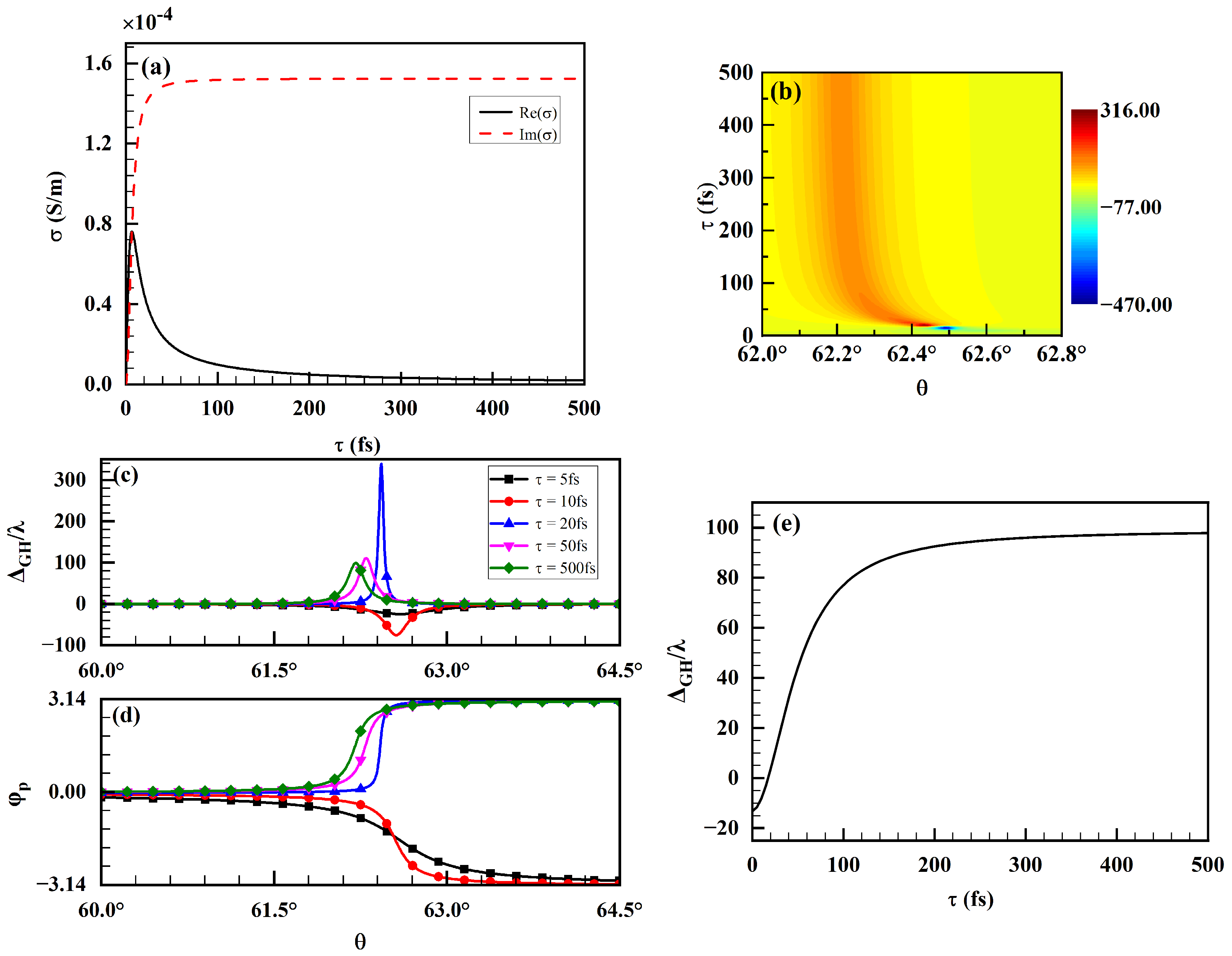
Next, we fix the Fermi energy E f to study the influence of the relaxation time τ on the spatial GH shifts. Figure 4a exhibits the real and imaginary parts of monolayer graphene conductivity as the function of relaxation time τ . As the relaxation time increases, the imaginary part of the graphene conductivity first increases and then starts to approach a constant value at τ = 50   fs , and the real part of the graphene conductivity first increases and then decreases. Thus, the relaxation time affects the position of the Brewster angle and the magnitude and sign of the GH shifts. Figure 4b shows the pseudo-color image of the GH shifts as a function of the relaxation time τ and incident angle θ . Figure 4c,d presents the dependence of the GH shifts and reflection phase φ p on the incident angle θ for different relaxation time τ , respectively. From Figure 4b, it is not difficult to find that the GH shifts switch from negative to positive at the relaxation time τ = 18   fs , and the GH shifts remain positive at τ > 18   fs and reach a maximum at τ = 20   fs . From Figure 4c,d, we can find that the angle corresponding to the maximum slope of the reflection phase φ p is the Brewster angle, and the positions of θ B are closely related to the relaxation time τ . The positions of θ B move to the smaller incident angle θ with the relaxation time τ increasing. When the relaxation time exceeds 50   fs , continuing to increase the relaxation time has little effect on the magnitude of GH shifts, which is due to the fact that the imaginary part of the graphene conductivity starts to approach a constant value at τ = 50   fs . Figure 4e depicts the variation in the GH shifts with the relaxation time τ at incident angle θ = 62.2 ° . As shown in Figure 4e, the GH shifts increase rapidly first and then come to a constant value with the increase in the relaxation time, so the effective adjustment range of the relaxation time to the magnitude of GH shifts is at about τ = 0 350   fs .
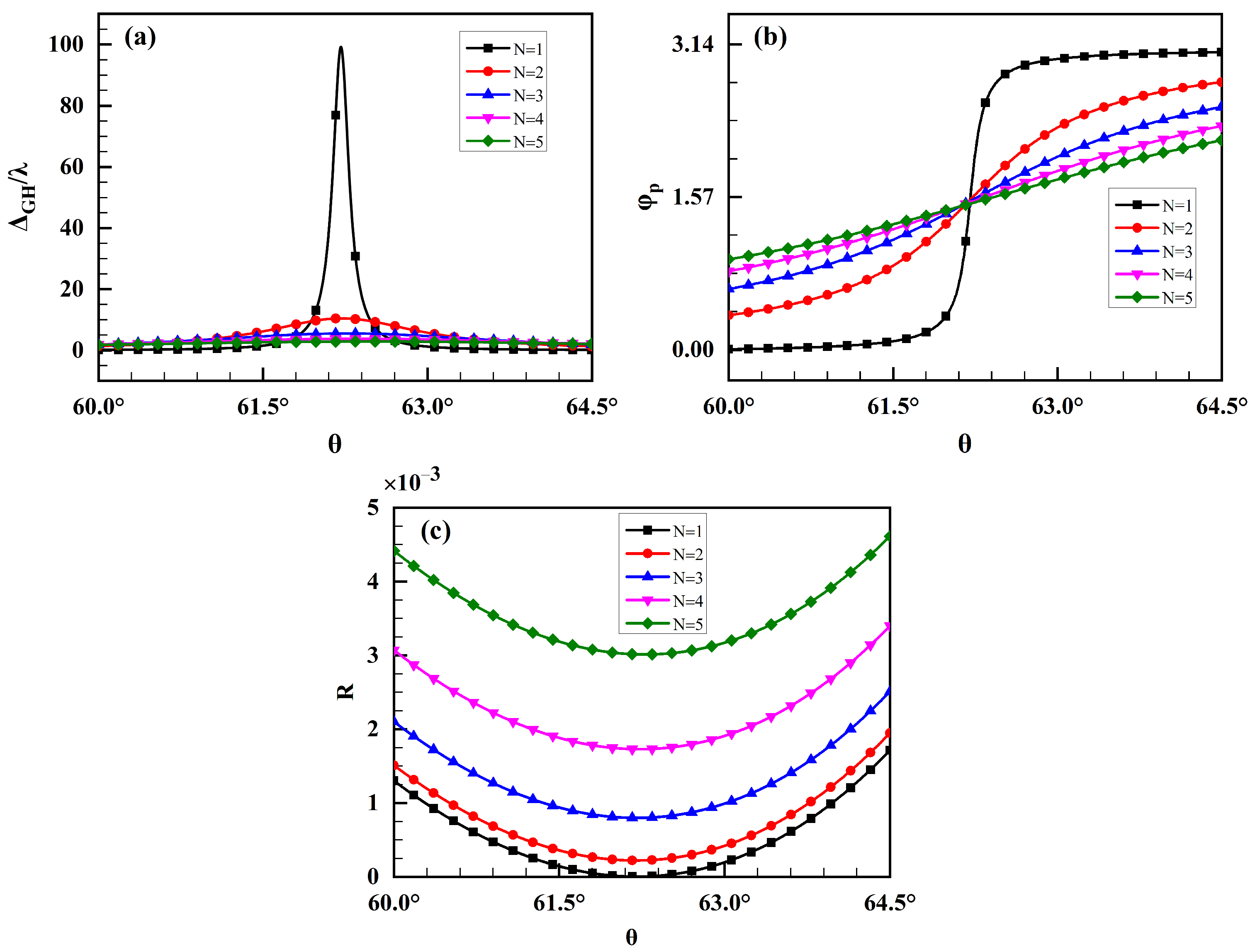
Then, we discuss the influence of layer numbers of graphene N on the GH shifts, as shown in Figure 5. From Equations (1) and (2), we can find that increasing the layer number of graphene is equal to enlarging the value of Femi energy; therefore, the layer numbers of graphene and Fermi energy have the same effects on the GH shifts. The layer numbers of graphene have no effect on the position of the Brewster angle but will affect the magnitude of the GH shifts. From Figure 5b,c, it can be observed that as the layer numbers of graphene increase, the slope of the reflection phase decreases while the reflectance increases, which leads to a corresponding decrease in the GH shift, as shown in Figure 5a. The GH shifts reach the maximum value at N = 1 , so the monolayer graphene/hBN heterostructure can be used for sensor sensitivity research.
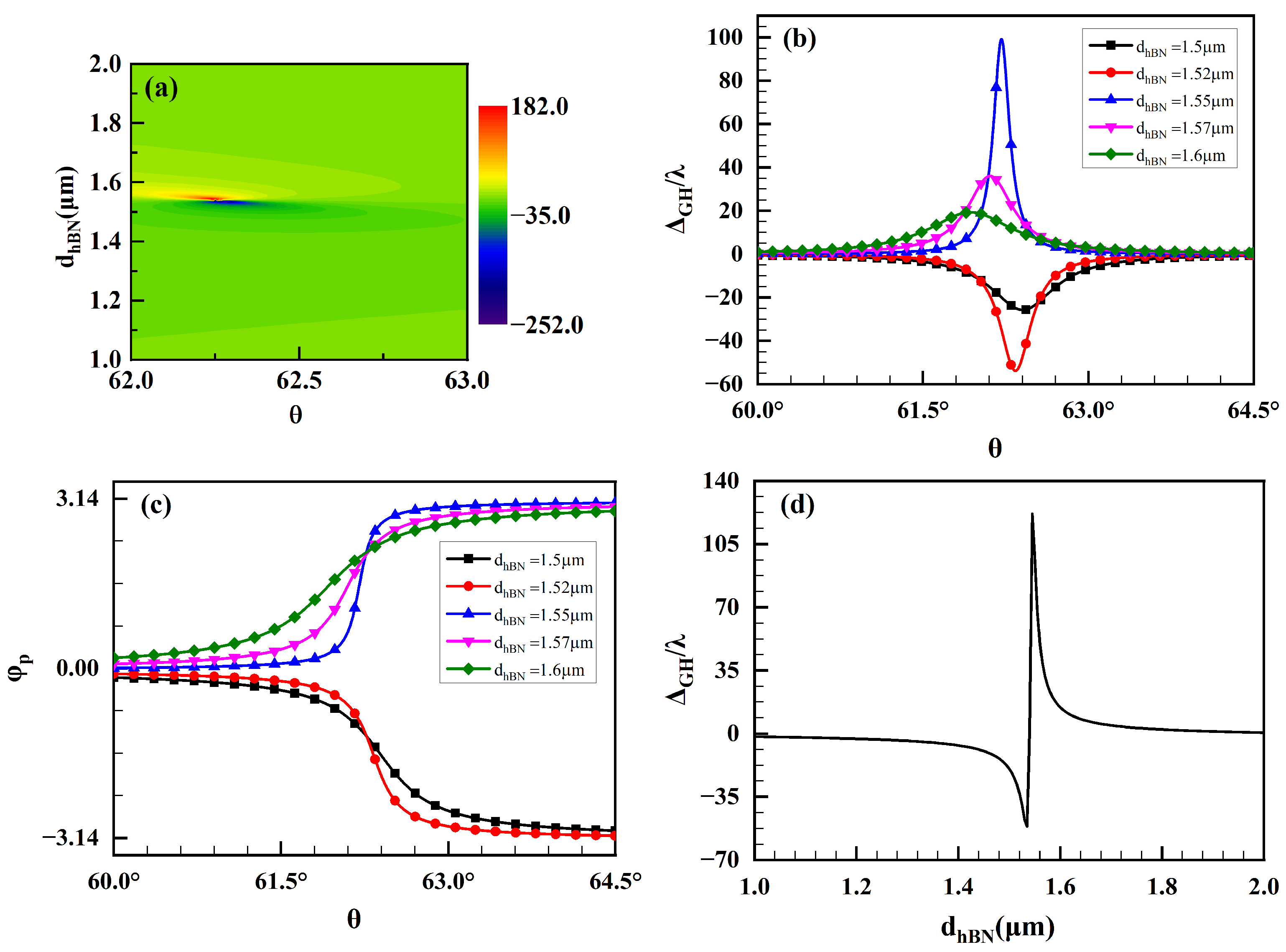
Finally, we investigate the effect of the hBN thickness d h B N on the GH shifts. Figure 6a depicts the pseudo-color image of the GH shifts with different hBN thickness d h B N and incident angle θ . Figure 6b,c presents the dependence of the GH shifts and reflection phase φ p on the incident angle θ for different hBN thickness d h B N , respectively. From Figure 6a, we can find that the larger GH shifts are mainly concentrated near d h B N = 1.54   μ m , and the GH shifts remain positive at d h B N > 1.54   μ m . Further, the positions of θ B are closely related to the hBN thickness d h B N . As shown in Figure 6b,c, the positions of θ B move to the smaller incident angle θ as the hBN thickness d h B N increases. The GH shifts are negative at d h B N = 1.5   μ m and 1.52   μ m , and the GH shifts are positive at d h B N = 1.55   μ m ,   1.57   μ m , and 1.6   μ m . Figure 6d shows the dependence of the GH shifts on the hBN thickness d h B N at incident angle θ = 62.2 ° . The variation in the GH shifts with the hBN thickness exhibits hyperbolicity. The GH shifts jump from negative maximum value to positive maximum value when the hBN thickness increases from 1.535   μ m to 1.545   μ m . Near d h B N = 1.54   μ m , small changes in hBN thickness d h B N can cause large changes in GH shifts. Hence, we can choose the appropriate hBN thickness to obtain the desired GH shifts.

3.2. Effects of Airy Vortex Beam Parameters

In this section, we study the influences of Airy vortex beam parameters on the spatial GH shifts. The parameters of graphene/hBN heterostructure are set to E f = 0.2   eV , N = 1 , τ = 500   fs , and d h B N = 1.55   μ m . The beam width of the incident Airy vortex beam is w 0 = 1   mm . First, we discuss the influence of the decay factor on the GH shifts. Figure 7a–c present the dependence of the GH shifts on the incident angle θ for different decay factors in the x direction, y direction, and 45° direction, respectively. We can find that the change in the decay factor in the y direction and 45° direction has little effect on the GH shift, while the change in the decay factor in the x direction has a great effect on the GH shift, which is due to the fact that spatial GH shift is the displacement of the beam centroid in the x-z plane [41]. As shown in Figure 7a, the magnitude of the GH shift decreases as the decay factor in the x direction increases. At the decay factors ( α , β ) = ( 0.01 , 0.1 ) and ( 0.03 , 0.1 ) , the GH shifts rise rapidly from negative maximum value to positive maximum value near the incident angle θ = 62.2 ° . Comparing Figure 7a with Figure 7c, we can find that the asymmetry of the Airy vortex beam field distribution in the x direction and y direction is the main reason for the huge GH shift. Therefore, the large GH shifts can be obtained by adjusting the decay factor in the x direction.
Next, we discuss the influence of the vortex position on the GH shifts. Figure 8a–c show the variation in the GH shifts with the incident angle θ for the vortex positions at the x-axis, y-axis, and 45°-axis, respectively. The vortex position will affect the position of the Brewster angle. The position of the Brewster angle keeps invariable when the vortex position at the x-axis changes, while the position of the Brewster angle changes with the vortex position at the y-axis, as shown in Figure 8a,b. Meanwhile, the vortex position affects the magnitude and sign of GH shifts. The GH shifts are positive, with the vortex located at ( 0 , 0 ) , ( 0.001 , 0 ) , ( 0 , 0.001 ) , and ( 0.001 , 0.001 ) , while the GH shifts are negative, with the vortex located at ( 0.01 , 0 ) , ( 0 , 0.01 ) , ( 0.01 , 0.01 ) , ( 0.1 , 0 ) , ( 0 , 0.1 ) , and ( 0.1 , 0.1 ) . When the vortex is located at ( 0.001 , 0 ) , ( 0 , 0.001 ) , and ( 0.001 , 0.001 ) , the change in the vortex position has a greater effect on the GH shift, but when the vortex is located at ( 0.1 , 0 ) , ( 0 , 0.1 ) , and ( 0.1 , 0.1 ) , the change in the vortex position has no effect on the GH shift. In other words, the further the distance of the vortex position from the origin point is, the smaller the influence of the vortex position on the intensity distribution of the Airy vortex beam is, so the smaller the influence of the vortex position on GH shift.

3.3. Spatial GH Shifts for Sensing

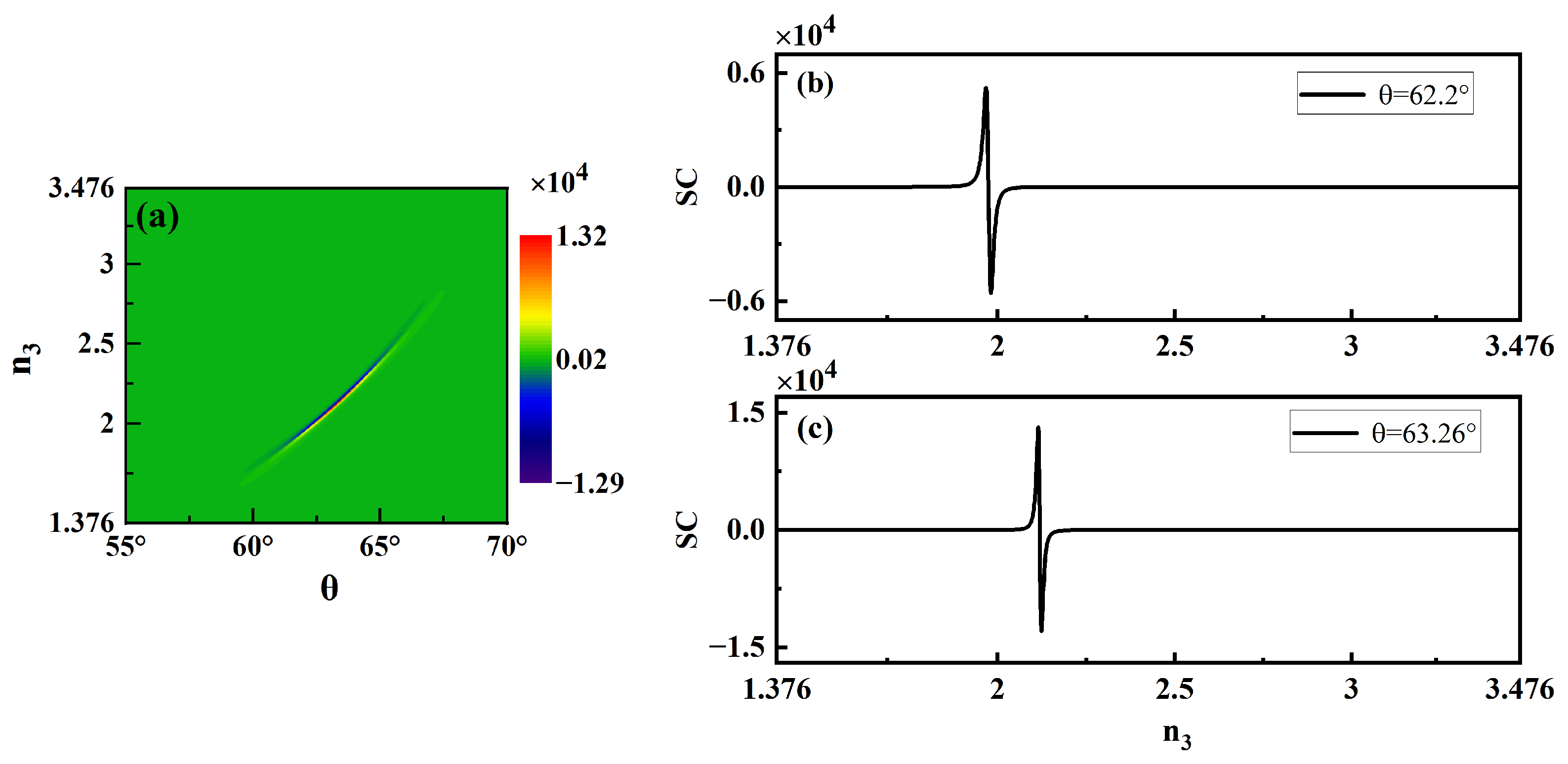
The spatial GH shift is sensitive to the refractive index of the substrate, so the graphene/hBN heterostructure can be used to design sensors or optical switches. The refractive index of the substrate is n 3 . The sensitivity coefficient (SC) represents the sensitivity of sensors in detecting physical quantities, which is defined as the differential of the GH shifts with the refractive index n 3 [83]. Figure 9a depicts the pseudo-color image of the SC of the GH shifts with different substrate refractive index n 3 and incident angle θ . The SC is flexibly tunable by altering the substrate refractive index or the incident angle. We choose two incident angles, θ = 62.2 ° and θ = 63.26 ° , to observe the variation in the SC with the refractive index n 3 , as shown in Figure 9b,c. Figure 9b,c displays that a positive peak appears initially and then a negative valley is generated at incident angles θ = 62.2 ° and θ = 63.26 ° , while the polarity of SC switches at n 3 = 1.97 and n 3 = 2.12 at incident angles θ = 62.2 ° and θ = 63.26 ° , respectively. The SC reaches the positive maximum value 1.32 × 10 4 at the incident angle θ = 63.26 ° and the refractive index n 3 = 2.12 . The graphene/hBN heterostructure possesses a simple structure and tunable sensitivity, which can be used for optical sensors and precision measurement.

4. Conclusions

In conclusion, we present a full analytical theory for the spatial GH shifts of the Airy vortex beams impinging on graphene/hBN heterostructure. Based on the angular spectrum expansion, the exact analytical expression of the spatial GH shift is derived. By simulating the reflectance of the graphene/hBN heterostructure with different a wavelength and incident angle, the appropriate wavelength and incident angle are obtained to enhance the GH shift. Then, we studied the control of the GH shifts from heterostructure parameters and incident beam parameters. For the graphene/hBN heterostructure, the relaxation time and hBN thickness affect the position of the Brewster angle and the magnitude and sign of the GH shifts, while the layer numbers of graphene and the Fermi energy have no effect on the position of the Brewster angle. The GH shifts are maximum for monolayer graphene, and the positive and negative switching of GH shifts can be realized easily by tuning the Fermi energy without changing the position of the Brewster angle. Moreover, the variation in the GH shifts with the Fermi energy and hBN thickness is hyperbolic at the Brewster angle, similar to the variation in the permittivity of hBN. For the incident Airy vortex beam, the vortex position and the decay factor in the x direction have a great effect on the GH shifts. The influence of the vortex position on the GH shift is related to the distance of the vortex position from the origin point; the further the distance, the smaller the influence, and the magnitude and sign of GH shifts at a certain Brewster angle can be controlled by adjusting the vortex position at the x-axis. In addition, the decay factor in the x direction has a significant regulatory effect on the GH shift. The GH shift can reach as high as 1042 λ at the decay factors ( α , β ) = ( 0.01 , 0.1 ) . Our results might provide a novel perspective to enhance the GH shifts. Moreover, due to high sensitivity of the beam shift to the parameters of the interface, the results may provide some theoretical supports for the applications of the GH shifts in precision measurement and optical sensing.

Author Contributions

Conceptualization and methodology, X.Y. and T.Q.; software, X.Y.; validation, Z.W., T.Q. and Z.L.; formal analysis, X.Y., T.Q. and Z.L.; investigation, X.Y, T.Q. and Z.L.; resources, Z.W. and T.Q.; writing—original draft preparation, X.Y. and T.Q.; writing—review and editing, X.Y. and T.Q.; visualization, X.Y., Z.L. and Z.W.; supervision, T.Q.; funding acquisition, Z.W. and T.Q. All authors have read and agreed to the published version of the manuscript.

Funding

This research was funded by the National Natural Science Foundation of China (62071359, 62171355, 62201566), Natural Science Basic Research Program of Shaanxi Province (2021JM-135), Postdoctoral Science Foundation in Shaanxi Province and the Fundamental Research Funds for the Central Universities (XJS222703), Scientific Research Program Funded by Shaanxi Provincial Education Department (No. 20JS059).

Institutional Review Board Statement

Not applicable.

Informed Consent Statement

Not applicable.

Data Availability Statement

The original contributions presented in this study are included in the article. Further inquiries can be directed to the corresponding author.

Acknowledgments

Thanks to the anonymous reviewers for valuable suggestions for improving the manuscript quality.

Conflicts of Interest

The authors declare no conflict of interest.

References

  1. Efremidis, N.K.; Chen, Z.; Segev, M.; Christodoulides, D.N. Airy beams and accelerating waves: An overview of recent advances. Optica 2019, 6, 686–701. [Google Scholar] [CrossRef]
  2. Berry, M.V.; Balazs, N.L. Nonspreading wave packets. Am. J. Phys. 1979, 47, 264–267. [Google Scholar] [CrossRef]
  3. Siviloglou, G.A.; Broky, J.; Dogariu, A.; Christodoulides, D.N. Observation of accelerating Airy beams. Phys. Rev. Lett. 2007, 99, 213901. [Google Scholar] [CrossRef] [PubMed]
  4. Siviloglou, G.A.; Christodoulides, D.N. Accelerating finite energy Airy beams. Opt. Lett. 2007, 32, 979–981. [Google Scholar] [CrossRef]
  5. Siviloglou, G.A.; Broky, J.; Dogariu, A.; Christodoulides, D.N. Ballistic dynamics of Airy beams. Opt. Lett. 2008, 33, 207–209. [Google Scholar] [CrossRef]
  6. Broky, J.; Siviloglou, G.A.; Dogariu, A.; Christodoulides, D.N. Self-healing properties of optical Airy beams. Opt. Express 2008, 16, 12880–12891. [Google Scholar] [CrossRef]
  7. Gu, Y.; Gbur, G. Scintillation of Airy beam arrays in atmospheric turbulence. Opt. Lett. 2010, 35, 3456–3458. [Google Scholar] [CrossRef] [PubMed]
  8. Baumgartl, J.; Mazilu, M.; Dholakia, K. Optically mediated particle clearing using Airy wavepackets. Nat. Photonics 2008, 2, 675–678. [Google Scholar] [CrossRef]
  9. Zhang, P.; Prakash, J.; Zhang, Z.; Mills, M.S.; Efremidis, N.K.; Christodoulides, D.N.; Chen, Z. Trapping and guiding microparticles with morphing autofocusing Airy beams. Opt. Lett. 2011, 36, 2883–2885. [Google Scholar] [CrossRef]
  10. Suarez, R.A.B.; Neves, A.A.R.; Gesualdi, M.R.R. Optical trapping with non-diffracting Airy beams array using a holographic optical tweezers. Opt. Laser Technol. 2021, 135, 106678. [Google Scholar] [CrossRef]
  11. Polynkin, P.; Kolesik, M.; Moloney, J.V.; Siviloglou, G.A.; Christodoulides, D.N. Curved Plasma Channel Generation Using Ultraintense Airy Beams. Science 2009, 324, 229–232. [Google Scholar] [CrossRef] [PubMed]
  12. Polynkin, P.; Kolesik, M.; Moloney, J. Filamentation of femtosecond laser Airy beams in water. Phys. Rev. Lett. 2009, 103, 123902. [Google Scholar] [CrossRef] [PubMed]
  13. Li, J.; Fan, X.; Zang, W.; Tian, J. Vacuum electron acceleration driven by two crossed Airy beams. Opt. Lett. 2011, 36, 648–650. [Google Scholar] [CrossRef] [PubMed]
  14. Salandrino, A.; Christodoulides, D.N. Airy plasmon: A nondiffracting surface wave. Opt. Lett. 2010, 35, 2082–2084. [Google Scholar] [CrossRef]
  15. Minovich, A.; Klein, A.E.; Janunts, N.; Pertsch, T.; Neshev, D.N.; Kivshar, Y.S. Generation and Near-Field Imaging of Airy Surface Plasmons. Phys. Rev. Lett. 2011, 107, 116802. [Google Scholar] [CrossRef] [PubMed]
  16. Ng, J.; Lin, Z.; Chan, C.T. Theory of optical trapping by an optical vortex beam. Phys. Rev. Lett. 2010, 104, 103601. [Google Scholar] [CrossRef] [PubMed]
  17. Dholakia, K.; Čižmár, T. Shaping the future of manipulation. Nat. Photonics 2011, 5, 335–342. [Google Scholar] [CrossRef]
  18. Gibson, G.; Courtial, J.; Padgett, M.J. Free-space information transfer using light beams carrying orbital angular momentum. Opt. Express 2004, 12, 5448–5456. [Google Scholar] [CrossRef]
  19. Wang, J.; Yang, J.-Y.; Fazal, I.M.; Ahmed, N.; Yan, Y.; Huang, H.; Ren, Y.; Yue, Y.; Dolinar, S.; Tur, M.; et al. Terabit free-space data transmission employing orbital angular momentum multiplexing. Nat. Photonics 2012, 6, 488–496. [Google Scholar] [CrossRef]
  20. Molina-Terriza, G.; Torres, J.P.; Torner, L. Twisted photons. Nat. Phys. 2007, 3, 305–310. [Google Scholar] [CrossRef]
  21. Mazilu, M.; Baumgartl, J.; Cizmar, T.; Dholakia, K. Accelerating vortices in Airy beams. Proc. SPIE 2009, 7430, 74300C. [Google Scholar] [CrossRef]
  22. Dai, H.T.; Liu, Y.J.; Luo, D.; Sun, X.W. Propagation properties of an optical vortex carried by an Airy beam: Experimental implementation. Opt. Lett. 2011, 36, 1617–1619. [Google Scholar] [CrossRef] [PubMed]
  23. Suarez, R.A.B.; Neves, A.A.R.; Gesualdi, M.R.R. Generation and characterization of an array of Airy-vortex beams. Opt. Commun. 2020, 458, 124846. [Google Scholar] [CrossRef]
  24. Gao, M.; Wang, G.; Yang, X.; Liu, H.; Deng, D. Goos-Hänchen and Imbert-Fedorov shifts of off-axis Airy vortex beams. Opt. Express 2020, 28, 28916–28923. [Google Scholar] [CrossRef]
  25. Fang, Z.X.; Chen, Y.; Ren, Y.X.; Gong, L.; Wang, P. Interplay between topological phase and self-acceleration in a vortex symmetric Airy beam. Opt. Express 2018, 26, 7324–7335. [Google Scholar] [CrossRef] [PubMed]
  26. Casiraghi, C.; Hartschuh, A.; Lidorikis, E.; Qian, H.; Harutyunyan, H.; Gokus, T.; Novoselov, K.S.; Ferrari, A.C. Rayleigh Imaging of Graphene and Graphene Layers. Nano Lett. 2007, 7, 2711–2717. [Google Scholar] [CrossRef] [PubMed]
  27. Geim, A.K. Graphene: Status and Prospects. Science 2009, 324, 1530–1534. [Google Scholar] [CrossRef]
  28. Yankowitz, M.; Xue, J.; LeRoy, B.J. Graphene on hexagonal boron nitride. J. Phys. Condens. Matter 2014, 26, 303201. [Google Scholar] [CrossRef]
  29. Kumar, A.; Low, T.; Fung, K.H.; Avouris, P.; Fang, N.X. Tunable Light–Matter Interaction and the Role of Hyperbolicity in Graphene–hBN System. Nano Lett. 2015, 15, 3172–3180. [Google Scholar] [CrossRef] [PubMed]
  30. Dean, C.R.; Young, A.F.; Meric, I.; Lee, C.; Wang, L.; Sorgenfrei, S.; Watanabe, K.; Taniguchi, T.; Kim, P.; Shepard, K.L.; et al. Boron nitride substrates for high-quality graphene electronics. Nat. Nanotechnol. 2010, 5, 722–726. [Google Scholar] [CrossRef] [PubMed]
  31. Dai, S.; Ma, Q.; Liu, M.K.; Andersen, T.; Fei, Z.; Goldflam, M.D.; Wagner, M.; Watanabe, K.; Taniguchi, T.; Thiemens, M.; et al. Graphene on hexagonal boron nitride as a tunable hyperbolic metamaterial. Nat. Nanotechnol. 2015, 10, 682–686. [Google Scholar] [CrossRef]
  32. Brar, V.W.; Jang, M.S.; Sherrott, M.; Kim, S.; Lopez, J.J.; Kim, L.B.; Choi, M.; Atwater, H. Hybrid Surface-Phonon-Plasmon Polariton Modes in Graphene/Monolayer h-BN Heterostructures. Nano Lett. 2014, 14, 3876–3880. [Google Scholar] [CrossRef] [PubMed]
  33. Zhao, B.; Zhang, Z.M. Enhanced Photon Tunneling by Surface Plasmon–Phonon Polaritons in Graphene/hBN Heterostructures. J. Heat Transf. 2016, 139, 022701. [Google Scholar] [CrossRef]
  34. Wu, J.; Jiang, L.; Guo, J.; Dai, X.; Xiang, Y.; Wen, S. Tunable perfect absorption at infrared frequencies by a graphene-hBN hyper crystal. Opt. Express 2016, 24, 17103–17114. [Google Scholar] [CrossRef] [PubMed]
  35. Hajian, H.; Ghobadi, A.; Butun, B.; Ozbay, E. Tunable, omnidirectional, and nearly perfect resonant absorptions by a graphene-hBN-based hole array metamaterial. Opt. Express 2018, 26, 16940–16954. [Google Scholar] [CrossRef]
  36. Deng, G.; Song, X.; Dereshgi, S.A.; Xu, H.; Aydin, K. Tunable multi-wavelength absorption in mid-IR region based on a hybrid patterned graphene-hBN structure. Opt. Express 2019, 27, 23576–23584. [Google Scholar] [CrossRef]
  37. Zheng, Z.; Lu, F.; Dai, X. Tunable reflected group delay from the graphene/hBN heterostructure at infrared frequencies. Results Phys. 2019, 15, 102681. [Google Scholar] [CrossRef]
  38. Born, M.; Wolf, E. Principles of Optics; Cambridge University Press: Cambridge, UK, 1999. [Google Scholar]
  39. Goos, V.F.; Hänchen, H. Ein neuer und fundamentaler Versuch zur Totalreflexion. Ann. Phys. 1947, 436, 333–346. [Google Scholar] [CrossRef]
  40. Fedorov, F.I. K teorii polnovo otrazenija. Dokl. Akad. Nauk SSSR 1955, 105, 465–467. [Google Scholar]
  41. Bliokh, K.Y.; Aiello, A. Goos-Hänchen and Imbert-Fedorov beam shifts: An overview. J. Opt. 2013, 15, 014001. [Google Scholar] [CrossRef]
  42. Aiello, A.; Woerdman, J.P. Theory of angular Goos-Hänchen shift near Brewster incidence. arXiv 2009, arXiv:0903.3730v2. [Google Scholar]
  43. Zhen, W.; Deng, D.; Guo, J. Goos-Hänchen shifts of Gaussian beams reflected from surfaces coated with cross-anisotropic metasurfaces. Opt. Laser Technol. 2021, 135, 106679. [Google Scholar] [CrossRef]
  44. Fan, G.; Ding, Y.; Guo, J.; Deng, D. Goos–Hänchen and Imbert–Fedorov shifts for rotational elliptical Gaussian beams impinging on graphene–substrate surfaces. Opt. Commun. 2023, 538, 129455. [Google Scholar] [CrossRef]
  45. Ornigotti, M.; Aiello, A. Goos–Hänchen and Imbert–Fedorov shifts for bounded wavepackets of light. J. Opt. 2013, 15, 014004. [Google Scholar] [CrossRef]
  46. Ou, J.; Jiang, Y.; Zhang, J.; He, Y. Reflection of Laguerre-Gaussian beams carrying orbital angular momentum: A full Taylor expanded solution. J. Opt. Soc. Am. A 2013, 30, 2561–2571. [Google Scholar] [CrossRef] [PubMed]
  47. Aiello, A. Goos–Hänchen and Imbert–Fedorov shifts: A novel perspective. New J. Phys. 2012, 14, 013058. [Google Scholar] [CrossRef]
  48. Prajapati, C.; Ranganathan, D. Goos-Hanchen and Imbert-Fedorov shifts for Hermite-Gauss beams. J. Opt. Soc. Am. A 2012, 29, 1377–1382. [Google Scholar] [CrossRef]
  49. Aiello, A.; Woerdman, J.P. Goos–Hänchen and Imbert–Fedorov shifts of a nondiffracting Bessel beam. Opt. Lett. 2011, 36, 543–545. [Google Scholar] [CrossRef]
  50. Ornigotti, M. Goos-Hänchen and Imbert-Fedorov shifts for Airy beams. Opt. Lett. 2018, 43, 1411–1414. [Google Scholar] [CrossRef]
  51. Gao, M.; Deng, D. Spatial Goos-Hänchen and Imbert-Fedorov shifts of rotational 2-D finite energy Airy beams. Opt. Express 2020, 28, 10531–10541. [Google Scholar] [CrossRef]
  52. Zhen, W.; Deng, D. Goos-Hänchen shifts for Airy beams impinging on graphene-substrate surfaces. Opt. Express 2020, 28, 24104–24114. [Google Scholar] [CrossRef] [PubMed]
  53. Zhai, C.; Zhang, S. Goos-Hänchen shift of an Airy beam reflected in an epsilon-near-zero metamaterial. Optik 2019, 184, 234–240. [Google Scholar] [CrossRef]
  54. He, J.; Yi, J.; He, S. Giant negative Goos-Hänchen shifts for a photonic crystal with a negative effective index. Opt. Express 2006, 14, 3024–3029. [Google Scholar] [CrossRef]
  55. Felbacq, D.; Moreau, A.; Smaâli, R. Goos-Hänchen effect in the gaps of photonic crystals. Opt. Lett. 2003, 28, 1633–1635. [Google Scholar] [CrossRef]
  56. Berman, P.R. Goos-Hanchen shift in negatively refractive media. Phys. Rev. E 2002, 66, 067603. [Google Scholar] [CrossRef] [PubMed]
  57. Li, Z.; Chen, Z.; Li, Y.; Zhang, Z.; Zhuang, G.; Liu, J.; Meng, Y. Interference effect on Goos–Hänchen shifts of anisotropic medium interface. New J. Phys. 2023, 25, 123018. [Google Scholar] [CrossRef]
  58. Zhou, X.; Liu, S.; Ding, Y.; Min, L.; Luo, Z. Precise control of positive and negative Goos-Hänchen shifts in graphene. Carbon 2019, 149, 604–608. [Google Scholar] [CrossRef]
  59. Yan, Y.; Zha, M.; Liu, J.; Tu, J.; Liu, Z. Tunable giant goos-hänchen shift in Au-ReS2-graphene heterostructure. Opt. Lett. 2024, 49, 3484–3487. [Google Scholar] [CrossRef] [PubMed]
  60. Xu, Y.; Chan, C.T.; Chen, H. Goos-Hänchen effect in epsilon-near-zero metamaterials. Sci. Rep. 2015, 5, 8681. [Google Scholar] [CrossRef]
  61. Villegas, D.; Lazcano, Z.; Arriaga, J.; Pérez-Álvarez, R.; de León-Pérez, F. Goos–Hänchen shift for coupled vibrational modes in a semiconductor structure. J. Phys. Condens. Matter 2024, 36, 325301. [Google Scholar] [CrossRef]
  62. Chen, Y.; Chen, G.; Luo, M.; Chang, S.; Gao, S. Beam shifts controlled by orbital angular momentum in a guided-surface plasmon resonance structure with a four-level atomic medium. Opt. Express 2023, 31, 25253–25266. [Google Scholar] [CrossRef] [PubMed]
  63. Lu, Z.; Zhen, W.; Wang, G.; Deng, D.; Guo, J. Goos-Hänchen and Imbert-Fedorov shifts of reflected rotating elliptical Gaussian beams from surfaces coated with cross-anisotropic metasurfaces. Results Phys. 2021, 27, 104548. [Google Scholar] [CrossRef]
  64. Xue, T.; Li, Y.-B.; Song, H.-Y.; Wang, X.-G.; Zhang, Q.; Fu, S.-F.; Zhou, S.; Wang, X.-Z. Giant and controllable Goos–Hänchen shift of a reflective beam off a hyperbolic metasurface of polar crystals. Chin. Phys. B 2023, 33, 014207. [Google Scholar] [CrossRef]
  65. Töppel, F.; Ornigotti, M.; Aiello, A. Goos-Hänchen and Imbert-Fedorov shifts from a quantum-mechanical perspective. New J. Phys. 2013, 15, 113059. [Google Scholar] [CrossRef]
  66. Jayaswal, G.; Mistura, G.; Merano, M. Weak measurement of the Goos-Hänchen shift. Opt. Lett. 2013, 38, 1232–1234. [Google Scholar] [CrossRef] [PubMed]
  67. Zhou, X.; Sheng, L.; Ling, X. Photonic spin Hall effect enabled refractive index sensor using weak measurements. Sci. Rep. 2018, 8, 1221. [Google Scholar] [CrossRef] [PubMed]
  68. Han, L.; Hu, Z.; Pan, J.; Huang, T.; Luo, D. High-Sensitivity Goos-Hänchen Shifts Sensor Based on BlueP-TMDCs-Graphene Heterostructure. Sensors 2020, 20, 3605. [Google Scholar] [CrossRef]
  69. Zhou, X.; Ling, X.; Luo, H.; Wen, S. Identifying graphene layers via spin Hall effect of light. Appl. Phys. Lett. 2012, 101, 251602. [Google Scholar] [CrossRef]
  70. Chen, S.; Ling, X.; Shu, W.; Luo, H.; Wen, S. Precision Measurement of the Optical Conductivity of Atomically Thin Crystals via the Photonic Spin Hall Effect. Phys. Rev. Appl. 2020, 13, 014057. [Google Scholar] [CrossRef]
  71. Xu, D.; He, S.; Zhou, J.; Chen, S.; Wen, S.; Luo, H. Goos–Hänchen effect enabled optical differential operation and image edge detection. Appl. Phys. Lett. 2020, 116, 211103. [Google Scholar] [CrossRef]
  72. Chamorro-Posada, P.; Sanchez-Curto, J.; Aceves, A.B.; McDonald, G.S. Widely varying giant Goos-Hänchen shifts from Airy beams at nonlinear interfaces. Opt. Lett. 2014, 39, 1378–1381. [Google Scholar] [CrossRef] [PubMed]
  73. Song, H.; Chen, Z.; Li, Y.; Hao, S.; Zhang, Q.; Zhou, S.; Fu, S.; Wang, X. Large spatial shifts of a reflected Airy beam on the surface of hyperbolic crystals. J. Opt. Soc. Am. B 2023, 40, 1240. [Google Scholar] [CrossRef]
  74. Fan, Y.; Shen, N.-H.; Zhang, F.; Zhao, Q.; Wu, H.; Fu, Q.; Wei, Z.; Li, H.; Soukoulis, C.M. Graphene Plasmonics: A Platform for 2D Optics. Adv. Opt. Mater. 2019, 7, 1800537. [Google Scholar] [CrossRef]
  75. Fan, Y.; Shen, N.-H.; Zhang, F.; Wei, Z.; Li, H.; Zhao, Q.; Fu, Q.; Zhang, P.; Koschny, T.; Soukoulis, C.M. Electrically Tunable Goos–Hänchen Effect with Graphene in the Terahertz Regime. Adv. Opt. Mater. 2016, 4, 1824–1828. [Google Scholar] [CrossRef]
  76. Song, H.; Fu, S.; Zhang, Q.; Zhou, S.; Wang, X. Large spatial shifts of reflective beam at the surface of graphene/hBN metamaterials. Opt. Express 2021, 29, 19068–19083. [Google Scholar] [CrossRef] [PubMed]
  77. Liu, Z.; Lu, F.; Jiang, L.; Lin, W.; Zheng, Z. Tunable Goos-Hänchen Shift Surface Plasmon Resonance Sensor Based on Graphene-hBN Heterostructure. Biosensors 2021, 11, 201. [Google Scholar] [CrossRef]
  78. Zhao, Y.; Jin, G.; Zhou, S.; Zhang, Q.; Fu, S.F.; Wang, X.G.; Wang, X.Z. Giant goos-hänchen shift with heigh reflection base on guided mode resonance in trapezoidal hBN/dielectric metasurface. Phys. Scr. 2024, 99, 065540. [Google Scholar] [CrossRef]
  79. Hanson, G.W. Dyadic Green’s functions and guided surface waves for a surface conductivity model of graphene. J. Appl. Phys. 2008, 103, 064302. [Google Scholar] [CrossRef]
  80. Gusynin, V.P.; Sharapov, S.G.; Carbotte, J.P. Magneto-optical conductivity in graphene. J. Phys. Condens. Matter 2007, 19, 026222. [Google Scholar] [CrossRef]
  81. Yan, H.; Li, X.; Chandra, B.; Tulevski, G.; Wu, Y.; Freitag, M.; Zhu, W.; Avouris, P.; Xia, F. Tunable infrared plasmonic devices using graphene/insulator stacks. Nat. Nanotechnol. 2012, 7, 330–334. [Google Scholar] [CrossRef]
  82. Zhan, T.; Shi, X.; Dai, Y.; Liu, X.; Zi, J. Transfer matrix method for optics in graphene layers. J. Phys. Condens. Matter 2013, 25, 215301. [Google Scholar] [CrossRef] [PubMed]
  83. Zhao, D.; Ke, S.; Liu, Q.; Wang, B.; Lu, P. Giant Goos-Hänchen shifts in non-Hermitian dielectric multilayers incorporated with graphene. Opt. Express 2018, 26, 2817–2828. [Google Scholar] [CrossRef] [PubMed]
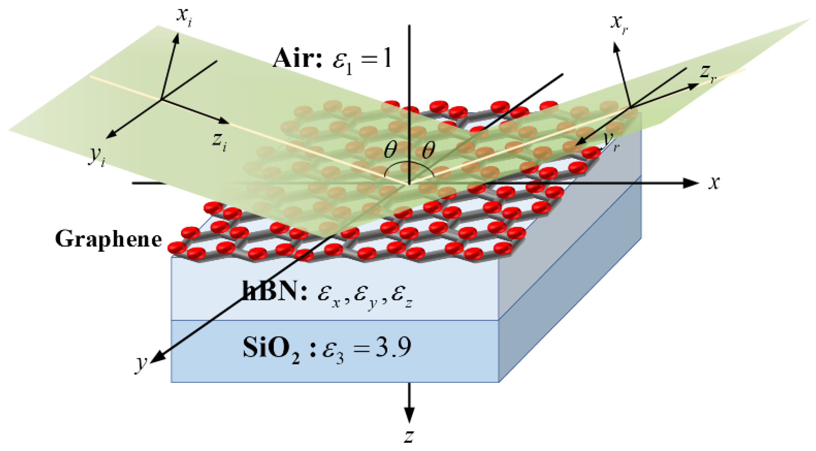
Figure 1. Coordinate system for the reflection of an Airy vortex beam impinging on a graphene/hBN heterostructure.
Photonics 12 00105 g001
Figure 2. (a) Real and imaginary parts of the permittivity of hBN. (b) Pseudo-color image of the reflectance of the graphene/hBN heterostructure as the function of wavelength and incident angle θ . (c) Reflectance as the function of wavelength for different incident angle θ . (d,e) The incident beams with wavelength λ 0 = 7.28   μ m , 12.2   μ m ,   and   12.72   μ m , and the variation in reflectance and reflection phase φ p with incident angle θ .
Photonics 12 00105 g002
Figure 3. (a) Real and imaginary parts of monolayer graphene conductivity as the function of Fermi energy E f . (b) Pseudo-color image of the GH shifts with Fermi energy E f and incident angle θ . (c) Dependence of the GH shifts on the incident angle θ for different Fermi energy E f . (d) Dependence of the reflection phase φ p on the incident angle θ for different Fermi energy E f . (e) At incident angle θ = 62.2 ° , the variation in the GH shifts with the Fermi energy E f . Here, graphene layer number N = 1 , relaxation time τ = 500   fs , and hBN thickness d h B N = 1.55   μ m .
Photonics 12 00105 g003
Figure 4. (a) Real and imaginary parts of monolayer graphene conductivity as the function of relaxation time τ . (b) Pseudo-color image of the GH shifts with relaxation time τ and incident angle θ . (c) Dependence of the GH shifts on the incident angle θ for different relaxation time τ . (d) Dependence of the reflection phase φ p on the incident angle θ for different relaxation time τ . (e) At incident angle θ = 62.2 ° , the variation in the GH shifts with the relaxation time τ . Here, graphene layer number N = 1 , Fermi energy E f = 0.2   eV , and hBN thickness d h B N = 1.55   μ m .
Photonics 12 00105 g004
Figure 5. (a) Dependence of the GH shifts on the incident angle θ for different layer numbers of graphene N . (b) Dependence of the reflection phase φ p on the incident angle θ for different layer numbers of graphene N . (c) Dependence of the reflectance R on the incident angle θ for different layer numbers of graphene N . Here, Fermi energy E f = 0.2   eV , relaxation time τ = 500   fs , and hBN thickness d h B N = 1.55   μ m .
Photonics 12 00105 g005
Figure 6. (a) Pseudo-color image of the GH shifts with hBN thickness d h B N and incident angle θ . (b) Dependence of the GH shifts on the incident angle θ for different hBN thickness d h B N . (c) Dependence of the reflection phase φ p on the incident angle θ for different hBN thickness d h B N . (d) At incident angle θ = 62.2 ° , the variation in the GH shifts with the hBN thickness d h B N . Here, graphene layer number N = 1 , Fermi energy E f = 0.2   eV , and relaxation time τ = 500   fs .
Photonics 12 00105 g006
Figure 7. Dependence of the GH shifts on the incident angle θ for different decay factor at (a) x direction, (b) y direction, and (c) 45° direction (α = β).
Photonics 12 00105 g007
Figure 8. Dependence of the GH shifts on the incident angle θ for different vortex position at (a) x-axis, (b) y-axis, and (c) 45°-axis.
Photonics 12 00105 g008
Figure 9. (a) Pseudo-color image of the SC of the GH shifts with substrate refractive index n 3 and incident angle θ . (b,c) Dependence of the SC of the GH shifts on substrate refractive index n 3 at incident angles θ = 62.2 ° and θ = 63.26 ° , respectively. Here, graphene layer number N = 1 , Fermi energy E f = 0.2   eV , hBN thickness d h B N = 1.55   μ m , and relaxation time τ = 500   fs .
Photonics 12 00105 g009
Disclaimer/Publisher’s Note: The statements, opinions and data contained in all publications are solely those of the individual author(s) and contributor(s) and not of MDPI and/or the editor(s). MDPI and/or the editor(s) disclaim responsibility for any injury to people or property resulting from any ideas, methods, instructions or products referred to in the content.