Article

Second-Order Topological States in Non-Hermitian Square Photonic Crystals

Department of Physics, Jiangsu University, Zhenjiang 212013, China
*
Author to whom correspondence should be addressed.
Photonics 2025, 12(11), 1087; https://doi.org/10.3390/photonics12111087
Submission received: 26 September 2025 / Revised: 24 October 2025 / Accepted: 28 October 2025 / Published: 4 November 2025
(This article belongs to the Special Issue Advanced Research in Topological Photonics)

Abstract

Non-Hermitian photonic crystals offer a versatile platform for observing exotic phenomena, including the non-Hermitian skin effect and higher-order topological phases. In this work, we construct non-Hermitian photonic crystals by embedding balanced gain and loss into a magneto-optical photonic medium. Within the associated supercell, we demonstrate the emergence of second-order topological corner states whose degeneracies are selectively lifted by non-Hermitian effects, while others remain protected. Remarkably, the bulk states exhibit strong unidirectional localization toward a single corner, providing unambiguous evidence of the non-Hermitian skin effect. The coexistence of higher-order corner states and the NHSE within the same photonic platform reveals an intricate interplay between crystalline symmetry and non-Hermitian topology. Beyond its fundamental intrigue, our approach offers a versatile means of engineering and controlling the non-Hermitian skin effect in realistic photonic architectures, paving the way for applications in topological nanolasers, robust light localization, and quantum photonic emulators.

1. Introduction

In recent years, photonic crystals (PCs) have attracted considerable attention thanks to their unique photonic band structures [1,2,3,4,5,6,7,8,9,10,11]. PCs, as artificial materials capable of manipulating light propagation through their periodic dielectric structures, provide a powerful platform for investigating diverse optical phenomena [12,13]. Their defining feature, the photonic bandgap, enables the inhibition of spontaneous emission and the precise guidance of photon behavior [14,15,16]. Despite challenges such as fabrication sensitivity and optical losses, their exceptional design flexibility makes them ideal candidates for exploring the convergence of non-Hermitian and topological physics. Such properties facilitate the emergence of diverse physical phenomena in PCs, including flat-band structures [17,18], Weyl points [19,20,21,22,23,24], and nodal rings [25,26]. By tailoring lattice symmetries and inter-unit couplings, PCs can further host higher-order topological states [27,28,29,30,31,32,33,34,35,36], as exemplified by the realization of corner states in square-lattice systems [37,38,39,40,41,42]. More recently, Kagome lattice PCs incorporating next-nearest-neighbor interactions have been shown to support the coexistence of distinct types of corner states [43,44]. Thanks to this versatility, PCs constitute an exceptional platform for probing topological states of light and matter. Beyond fundamental studies, their engineered topological modes have been harnessed for applications such as frequency-selective optical control [45,46] via chiral edge states [47,48,49,50] and the realization of the photonic valley Hall effect [51,52]. Incorporating nonlinear media, such as AlGaAs, further enhances nonreciprocal coupling between lattice sites [53], enabling nonlinear band topology control and associated phenomena [54,55]. These developments also create opportunities for practical applications in optical sensing [56,57,58,59,60,61,62,63,64,65,66,67,68,69,70,71,72,73,74,75,76], where precise control of light–matter interactions is essential.
Very recently, the study of non-Hermitian physics uncovered a wide range of unconventional, interesting phenomena that have no Hermitian counterparts [77,78,79,80,81,82,83,84,85,86,87,88,89,90,91,92], demonstrating effects such as the delocalization of higher-order topological states [93], hybrid skin-topological modes [94,95], and anomalous higher-order boundary states [96]. Furthermore, seminal works have revealed the two-dimensional non-Hermitian skin effect (NHSE) [97], non-Hermitian multiple topological transitions [98], and non-Hermitian Floquet higher-order topological states [99]. Among these, the NHSE has emerged as a defining phenomenon, reshaping conventional notions of bulk–boundary correspondence. In non-Hermitian systems, breaking time-reversal symmetry is crucial for generating novel physical phenomena such as the NHSE, forming the fundamental basis for characteristics like energy localization and the breakdown of the bulk–boundary correspondence. Non-Hermitian topological systems now constitute a paradigmatic framework within the field [100,101,102,103,104], giving rise to phenomena such as the degeneracy lifting of second-order Majorana corner modes in non-Hermitian topological superconductors [105]. Significant efforts have also been directed toward photonic realizations of non-Hermitian topology, which are achieved through nonreciprocal light transport in coupled-resonator optical waveguides [106,107,108,109,110] and patterned gain/loss distributions in PCs [111,112]. These approaches have enabled the observation of exotic effects such as exceptional points [113,114,115] and corner skin modes [116,117]. Nevertheless, despite rapid progress in non-Hermitian higher-order photonics, the coexistence of the NHSE with higher-order topological states in a single photonic crystal platform remains elusive, leaving a key unanswered question in the study of non-Hermitian topological matter.
In this work, we propose a novel non-Hermitian PC design that enables the coexistence of NHSE and second-order topological states within a unified supercell configuration. The gain/loss distribution in the PC is meticulously engineered to achieve directional localization of optical fields toward specific system boundaries. In addition, quantitative relationships are uncovered between the gain/loss parameters and both the intensity of field localization and the degree of degeneracy breaking in corner states. The introduction of a tensor permeability inherent to magneto-optical materials breaks the time-reversal symmetry of the system, thereby establishing the foundation for inducing the NHSE. This innovative non-Hermitian PC platform offers distinct advantages; the robustness of conventional topological PCs is preserved, while active control over the position and intensity of optical field localization is enabled through non-Hermitian effects. Numerical simulations based on COMSOL Multiphysics verified the exceptional performance of the proposed system in micro-scale optical field manipulation.

2. Non-Hermitian Square-Lattice Photonic Crystal

We propose a non-Hermitian square-lattice PC characterized by a complex relative permittivity incorporating spatially modulated gain/loss patterned distributions, with its representative unit cell (UC A) illustrated in Figure 1a. The gain (loss) is incorporated into the relative permittivity of the red (blue) medium, expressed as ε A = ε 1 ± i γ , where ε 1 = 12 is the real part and γ = 5 denotes the gain/loss. The relative permeability is a tensor, which is
μ A = 1.6 1.4 i 0 1.4 i 1.6 0 0 0 1 .
The radius of the air hole is R 1 = 0.48 a , where a is the lattice constant and ε air = 1 and μ air = I ( I is the identity matrix). By incorporating both complex permittivity and tensor permeability, this specific design simultaneously breaks time-reversal symmetry and introduces pronounced non-Hermitian effects.
Under periodic boundary conditions (PBCs), as shown in Figure 1b, the non-Hermitian PC exhibits a pronounced bandgap from 77.48 to 91.26 THz, indicated by the shaded region. Parity analysis of the z-component of the electric field( E z ) at high-symmetry points (color inset, where + and − denote even and odd parity, respectively) reveals a band inversion, confirming the nontrivial nature of this bandgap [41]. The lower left inset depicts the first Brillouin zone of square-lattice PCs, indicating the high-symmetry points( Γ , X , and M ) and the band structure scan path (red line).
For the designed square non-Hermitian PC, its bandgap characteristics are shown in Figure 1e. When the air hole radius R 1 falls within the range of 0.11 a to 0.49 a , the system consistently exhibits an open bandgap, and its topological nature remains stable without undergoing any topological phase transition. In the region where R 1 is less than 0.11 a , the system is gapless, which is outside the scope of this study. These results demonstrate that the topological properties of the bandgap in our proposed non-Hermitian PC are robust against geometric variations. This characteristic is more clearly observable in Figure 1f, where the bandgap size exhibits an overall increasing trend with respect to R 1 . The geometric parameter R 1 = 0.48 a was selected at a position where the bandgap width is relatively optimal.
Based on the plane wave expansion (PWE) method [118], the photonic band structure of a PC under transverse magnetic (TM) polarization is governed by the following eigenvalue equation [118]:
G η G G k + G · k + G E G = ω c 2 E G ,
where G is the reciprocal lattice vector, η G denotes the Fourier coefficient of 1 / ε ( r ) , and E G represents the Fourier amplitude of the electric field component E z . For a given real wave vector k , the eigenfrequency ω can be solved.
The inverse dispersion method addresses the inverse problem of the aforementioned equation by treating the frequency ω as a given parameter and solving for the wave vector k . The corresponding governing equation constitutes a generalized eigenvalue problem with k as the eigenvalue [119]:
A ω · Ψ = k B ω · Ψ .
For the TM polarization case, the equation presented above can be transformed into the following matrix form using the PWE method [119]:
D ω c E + ω c 1 LM 1 L ω c M D h e = k x h e .
Here, h and e define the tangential component of the magnetic field and the z-component of the electric field, while D and L are diagonal matrices with elements D g , g = n x g x + n y g y , and L g , g = n x g y n y g x , and E and M are Toeplitz matrices with elements E g , g = ε g g , and M g , g = μ g g , which are the Fourier amplitudes of ε ( r ) and μ ( r ) , respectively.
For non-Hermitian PCs, the eigenvalue k obtained from the solution may be a complex wave vector:
k = k + i k .
The real part k determines the phase propagation constant of the wave, while the imaginary part k characterizes its attenuation rate.
The UC of the Hermitian PC (UC B), as shown in Figure 1c, consists of dielectric rods with a radius of R 2 = 0.29 a . The rods are characterized by a relative permittivity ε B = 12 and a relative permeability tensor μ B = I . The background material is air. The band structure of the Hermitian PC reveals a complete bandgap (shaded region) in the Hermitian case. The insets in Figure 1d show the parity of E z at high-symmetry points, illustrating the topology of the bandgap, which is topologically trivial. Furthermore, the bandgap range of the chosen Hermitian PC is slightly larger than that of the non-Hermitian counterpart, an intentional outcome that facilitates better concentration of the supercell’s bulk state electric field distribution within the non-Hermitian regions.
Topological states form at the interface between UCs with distinct topological properties [41]. In this work, a simple Hermitian topologically trivial PC is employed to serve as the counterpart for interfacing with UCs A, for the purpose of generating and observing topological states.

3. Corner States in Non-Hermitian Photonic Supercell

To investigate second-order topological states in non-Hermitian PC systems, a box-type supercell was constructed by interfacing UCs A and UCs B, as illustrated in Figure 2a. Since this study focuses primarily on the properties of the non-Hermitian PC region, the central part of the supercell consists of an 18 × 18 matrix of UCs A, surrounded by six layers of UCs B, with an inset magnifying the corner structure to highlight the geometric detail. The boundaries of the supercell are defined by perfect electric conductor (PEC) conditions.
The discrete spectrum of modes for the supercell is shown in Figure 2b. Figure 2b presents a series of eigenstates comprising bulk states, edge states, and corner states, which are denoted by black, blue, and red markers, respectively. Clearly, a subset of edge states and four corner states exist in the bandgap of bulk states. The inset shows the four corner states, whose real parts are all distributed around 90.37 THz, with variations remaining within 0.01 THz, labeled sequentially as C 1 , C 2 , C 3 , and C 4 . To further investigate the impact of non-Hermiticity on the corner states, the discrete spectrum in the complex plane is presented in Figure 2c, using the same marking scheme for states and bandgap as in Figure 2b. Due to the introduction of non-Hermiticity, the fourfold degeneracy of the corner states in the square-lattice PC is lifted and splits into a twofold degeneracy; the corner states C 3 and C 4 exhibit zero imaginary parts, forming a degenerate pair, while the corner states C 1 and C 2 possess eigenfrequencies of 90.364 + 7.60 i THz and 90.364 7.60 i THz, respectively. Their imaginary parts are opposite in value, forming a complex conjugate pair in the frequency plane.
The four corner states exhibit a strongly localized electric field modulus ( E ) at the corners, with their specific positions correlated with the degeneracy properties discussed earlier. Under the influence of non-Hermiticity, state C 1 exhibits a negative imaginary part, and E C 1 is localized in the lower left corner (Figure 2d), whereas state C 2 has a positive imaginary part, and E C 2 is localized in the upper right corner (Figure 2e). This spatial distribution mirrors the symmetric arrangement of the patterned gain/loss distributions within the UC shown in Figure 1a. Meanwhile, the degenerate states C 3 and C 4 are localized at the upper-left and lower-right corners, respectively, as shown in Figure 2f,g. The splitting of the imaginary parts of the two corner states, C 1 and C 2 , exhibits a strong dependence on the gain/loss parameter. As shown in Figure 2h, which plots the variation of their imaginary parts with increasing non-Hermitian strength, a smooth linear relationship is observed. This indicates that the degree of splitting between these two corner states can be effectively controlled by tuning the gain/loss parameter.
The degeneracy characteristics of the corner states are closely linked to the distribution features introduced by gain and loss. To verify this correlation, we constructed another analogous non-Hermitian PC, modifying only the gain and loss distribution to a left–right symmetric configuration. The corresponding UC and simulation results are presented in Appendix A and Figure A1, where detailed interpretations are also provided. Due to the altered gain and loss distribution, while the four corner states remain two-fold degenerate, a notable separation in their imaginary parts emerges: one degenerate pair exhibits positive imaginary parts (gain-dominant), whereas the other displays negative imaginary parts (loss-dominant). This contrasts with the single pair of degenerate corner states with purely real eigenfrequencies shown in Figure 2. These findings demonstrate that the symmetric distribution of gain and loss within the unit cell significantly influences both the distribution and degeneracy behavior of the corner states.
The robustness of the corner states is verified in Appendix B, Figure A2. Although the topological invariants of the non-Hermitian PC cannot yet be precisely computed theoretically at the current research stage, we have demonstrated the stability of its topological states through the introduction of corner doping in additional simulation experiments. The spectral isolation of the corner states within the bandgap and the highly localized nature of their eigenfield distributions provide phenomenological support for their topological origin. Combined with the doping-based validation method employed in Appendix B, these findings further reinforce the topological nature of the corner states.

4. Non-Hermitian Skin Effect

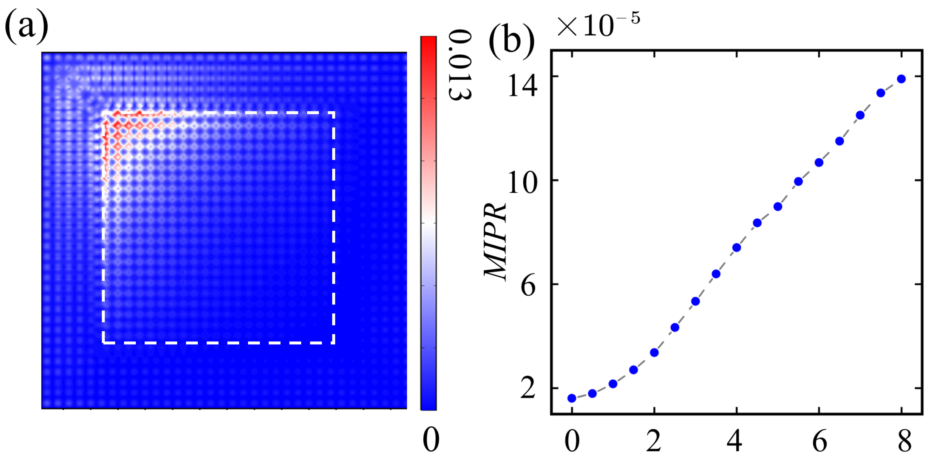
Non-Hermitian effects on this supercell not only break the degeneracy of corner states but also induce NHSE in the system. In the lattice framework, the NHSE is ubiquitously manifested in all bulk states. After normalization and averaging, the wave functions exhibit pronounced localization toward edges or corners, which constitutes a hallmark phenomenon in non-Hermitian systems. Based on the E of all bulk states corresponding to Figure 2b, we obtained a normalized average field E :
E = 1 M m = 1 M | E m , n | k = 1 N | E m , k | 2 ,
where M denotes the total number of eigenstates, N indicates the number of spatial data points per field, and | E m , n | corresponds to the electric field modulus value of the n-th data points (mesh points) of the supercell at the m-th eigenstate.
The numerical results are shown in Figure 3a. The field intensity exhibits a clear skew toward the upper-left corner, which is a characteristic signature of the NHSE. We employ the inverse participation ratio ( I P R ) to quantitatively evaluate the localization degree of the E and further compute its mean value ( M I P R ) as an indicator for the statistical analysis of the NHSE:
M I P R = 1 M m = 1 M n | E m , n | 4 n | E m , n | 2 2 ,
with the parameters M, N, m, n, and | E m , n | defined as in Equation (5).
As shown in Figure 3b, the mean inverse participation ratio ( M I P R ) increases significantly as the gain/loss parameter γ is raised, indicating that the localization of bulk optical fields originates from the introduction of non-Hermiticity and demonstrating that the degree of localization can be enhanced by increasing the non-Hermitian strength.
The NHSE in this supercell demonstrates remarkable robustness. To verify this property, we constructed a bulk-doped supercell model in Appendix B. The simulation results in Figure A3 show that while the introduced doping modifies the local electric field distribution near the perturbed region, it causes no significant changes to the system’s eigenfrequency spectrum or the fundamental field behavior in non-Hermitian regions. This outcome confirms both the adaptability of the NHSE to structural perturbations and the reliability of our implementation methodology.
The evolution diagram in Figure 3, depicting the M I P R of the bulk-state optical fields and the imaginary parts of the corner states versus the gain/loss parameter γ , not only clarifies the localization origin of bulk photonic fields through the NHSE but also reveals the smooth influence of non-Hermiticity on corner-state degeneracy. This confirms the validity and generality of our findings across the parameter range 0 < γ < 7 , with γ = 5 selected as a representative value. The choice of γ = 5 optimally balances two critical aspects; compared to larger γ values, second-order topological states exhibit stronger bandgap isolation under this parameter while simultaneously displaying more pronounced NHSEs in bulk-state optical fields than systems with smaller γ values.
The square PC possesses unique geometric symmetry. Compared to the hexagonal structure, its four right angles can more effectively exhibit the NHSE and more clearly demonstrate the selective degeneracy lifting of higher-order corner states. Due to the inherent obtuse angles of the hexagonal structure, it may, on one hand, suppress the manifestation of the NHSE and, on the other hand, make it difficult to clearly distinguish between topological states and bulk states influenced by the NHSE. It should be noted that this does not imply that non-Hermitian PCs with hexagonal structures constructed using the method proposed in this study cannot exhibit desirable phenomena. Rather, this research aims to employ a relatively simple square lattice model to more intuitively demonstrate a novel approach for constructing non-Hermitian PCs.

5. System with PBC x -OBC y

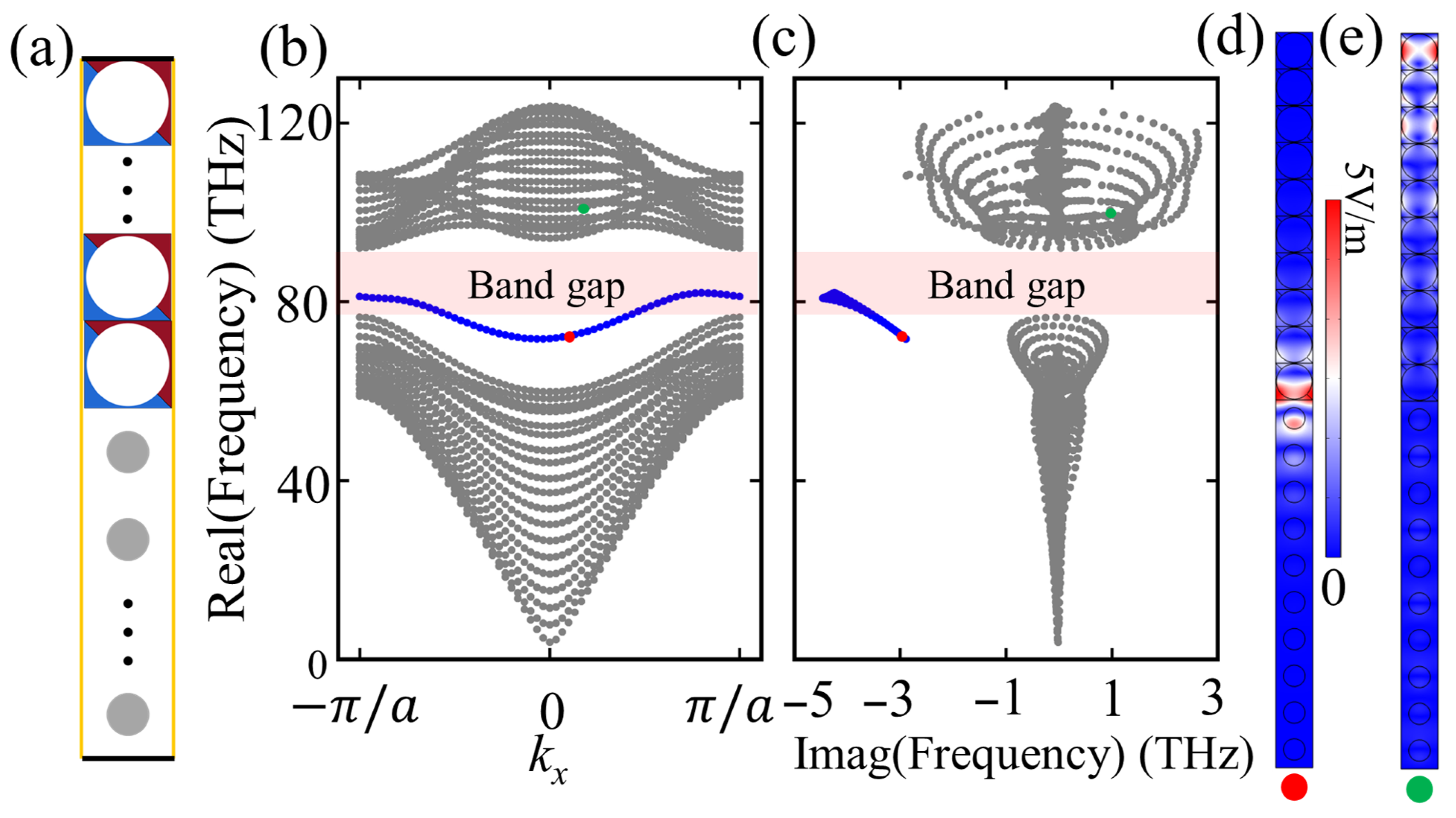
To investigate the origin of these second-order corner states and the NHSE, we construct a system with PBCs in the x-direction and OBCs in the y-direction, namely, a system with PBCx-OBCy, as illustrated in Figure 4a. This system consists of alternating UCs A and B, subjected to periodic (yellow) and PEC (black) boundary constraints. The eigenfrequency spectra shown in Figure 4b,c reveal isolated edge states (highlighted in blue) residing within the bandgap. A randomly selected edge state, marked by a red dot, shows its E distribution in Figure 4d. The field is clearly localized at the interface between UCs A and UCs B. These edge states serve as precursors to corner states, indicative of the hierarchical formation of second-order topological features. Furthermore, the bulk state indicated by the green marker in Figure 4e displays NHSE-driven localization at one boundary, paralleling the observations in the OBC system (Figure 2h).
The edge states that emerge under the PBCx-OBCy configuration share identical characteristics with those in Figure 2, appearing at the interface between UCs A and B and exhibiting spectral isolation within the bandgap. This behavior mirrors that of Hermitian systems and highlights the robust stability of edge states in the real-frequency domain. However, as evidenced in Figure 4c, these edge states possess substantial imaginary components in their eigenfrequencies, indicating that non-Hermitian effects exert a substantial influence on the imaginary frequency characteristics of topological modes. The second-order topological states observed in Figure 2 originate from the band gap opening in the edge states of the system with PBCx-OBCy (Figure 4), which is induced by the transition to OBC. Furthermore, the non-Hermitian framework profoundly reshapes both the eigenfrequency spectra and electric field distributions of bulk states under PBCx-OBCy, manifesting in the form of complex eigenfrequencies and spatially asymmetric field localization due to the NHSE. These findings collectively suggest that systems under PBCx-OBCy configurations provide an effective model for predicting the presence of NHSEs in fully open systems.

6. Conclusions

We propose a novel strategy for inducing the NHSE by incorporating spatially distributed gain/loss and tensor magnetic permeability into PCs. Our theoretical design can be implemented using realistic material systems such as YIG for nonreciprocity [120] and semiconductors for gain/loss [121], with further needed to fabricate materials that match the parameters used in this study. This establishes a viable pathway from theoretical concept to material-based realization.
The implemented system breaks time-reversal symmetry, thereby establishing a foundational framework for the coexistence of the NHSE with higher-order topological states in a single PC platform. While both studies focus on topological states in non-Hermitian PCs, our work demonstrates fundamental distinctions from corner skin modes. The corner skin mode emerges in higher-frequency bandgaps, where its electric field distribution characterizes the skin effect of edge states localizing at corners [116,117]. In contrast, our study reveals a coexisting system where bulk states exhibit the NHSE while second-order topological states persist simultaneously, and this approach not only deepens our understanding of non-Hermitian topological phenomena but also opens new avenues for the precise manipulation of optical field localization through geometric and material engineering. It should be noted that this study focuses exclusively on the linear optical properties of the proposed PC system. Within the linear regime, the core mechanism governing the coexistence of the NHSE and second-order topological states can be clearly demonstrated. Extending this work to incorporate nonlinear optical characteristics would introduce more complex parameter dependencies and potentially reveal novel physical phenomena, representing a highly valuable direction for our future research.
Although this configuration predominantly demonstrates field concentration effects in specific regions (e.g., the upper-left corner), the underlying localization mechanism exhibits universality and can be generalized to other non-Hermitian photonic lattice architectures. Furthermore, the patterned gain/loss distributions in this non-Hermitian system result in degeneracy lifting of the corner states; while two corner states maintain their degeneracy, the remaining pair exhibit identical real parts accompanied by opposite imaginary components in their eigenfrequencies. Crucially, the established quantitative correlation between the magnitude of the imaginary parts and the gain/loss parameters offers enhanced control over second-order topological states.

Author Contributions

Conceptualization, W.D.; methodology, W.D.; software, all authors; validation, Y.F.; formal analysis, W.D.; investigation, all authors; writing—original draft preparation, W.D.; writing—review and editing, Y.F.; supervision, Y.F.; project administration, W.D. All authors have read and agreed to the published version of the manuscript.

Funding

This research received no external funding.

Institutional Review Board Statement

Not applicable.

Informed Consent Statement

Not applicable.

Data Availability Statement

The data presented in this study are available within the article.

Acknowledgments

I express my sincere gratitude to Ji Xiang and Feng Yaru for their valuable discussions and insightful suggestions throughout this research. Their expertise and constructive feedback greatly contributed to the development of key ideas presented in this work.

Conflicts of Interest

The authors declare no conflicts of interest. The funders had no role in the design of this study; in the collection, analyses, or interpretation of data; in the writing of the manuscript; or in the decision to publish the results.

Abbreviations

The following abbreviations are used in this manuscript:
PCPhotonic crystal
UCUnit cell
NHSENon-Hermitian skin effect
PBCPeriod boundary condition
OBCOpen boundary condition
MIPRMean inverse participation ratio
PECPerfect electric conductor

Appendix A. Another Non-Hermitian PC

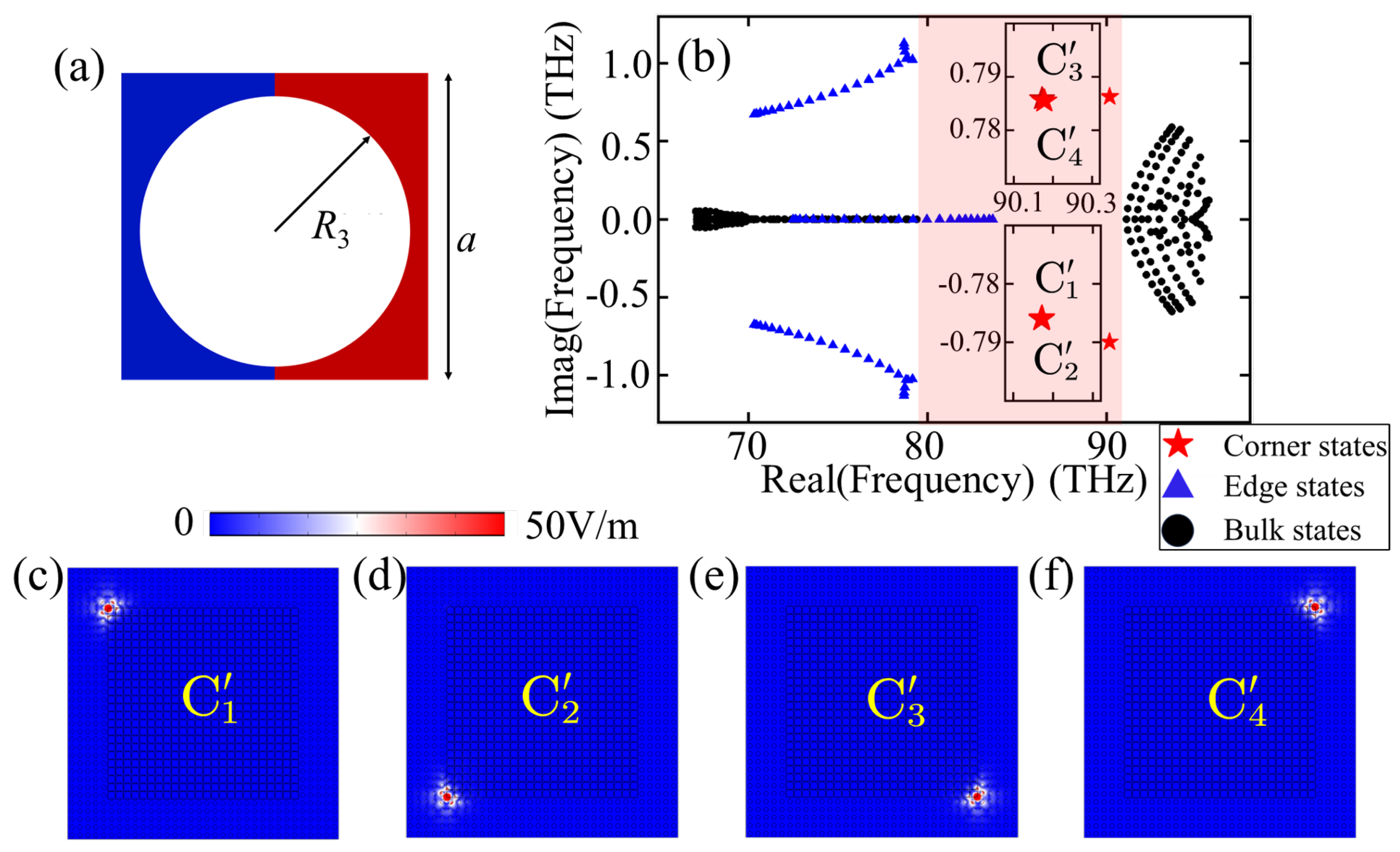
Under a certain preserved symmetric distribution, we investigated another non-Hermitian PC, as illustrated in Figure A1a. UC A: This unit cell (UC A′) features gain and loss distributed with left-right symmetry. We replaced the UCs A in the supercell of Figure 2a with UCs A′ and computed their eigenfrequencies and corresponding electric field distributions. The resulting eigenfrequency spectrum is presented in Figure A1b, where different topological states are distinguished using markers consistent with previous conventions.
Figure A1. (a) UC of another Non-Hermitian PC with an air hole radius of R 3 = R 1 = 0.48 a , red (blue) region corresponds to gain (loss). (b) Eigenfrequency spectrum of a supercell consisting of an 18 × 18 matrix of UCs A’ and six layers of UCs B. The bulk states, edge states, and corner states are denoted by points, triangles, and stars, respectively. Four corner states are labeled as C 1 C 4 and shown in insets according to their ordering. (cf) The | E | distributions of C 1 C 4 .
Photonics 12 01087 g0a1
Notably, besides distinct bandgaps and the relatively small imaginary parts of bulk states, the four corner states exhibit a fundamentally different pattern of two-fold degeneracy. Specifically, C 1 and C 2 form a degenerate pair with positive imaginary parts, localized on the left side of the system (Figure A1c,d), while C 3 and C 4 constitute another degenerate pair with negative imaginary parts, localized on the right side (Figure A1e,f). Between nondegenerate corner states, the real parts of their eigenfrequencies are identical, while their imaginary parts are opposite in sign. This alteration in the degeneracy pattern clearly demonstrates that the degeneracy of higher-order eigenstates in our designed non-Hermitian PC is strongly correlated with the symmetric distribution of gain and loss within the UC.

Appendix B. Introduction of Dopant Perturbations in the Supercell
To systematically assess the robustness of higher-order topological states and evaluate the NHSE, we constructed two distinct perturbation models within the supercell: corner doping and bulk doping, respectively.
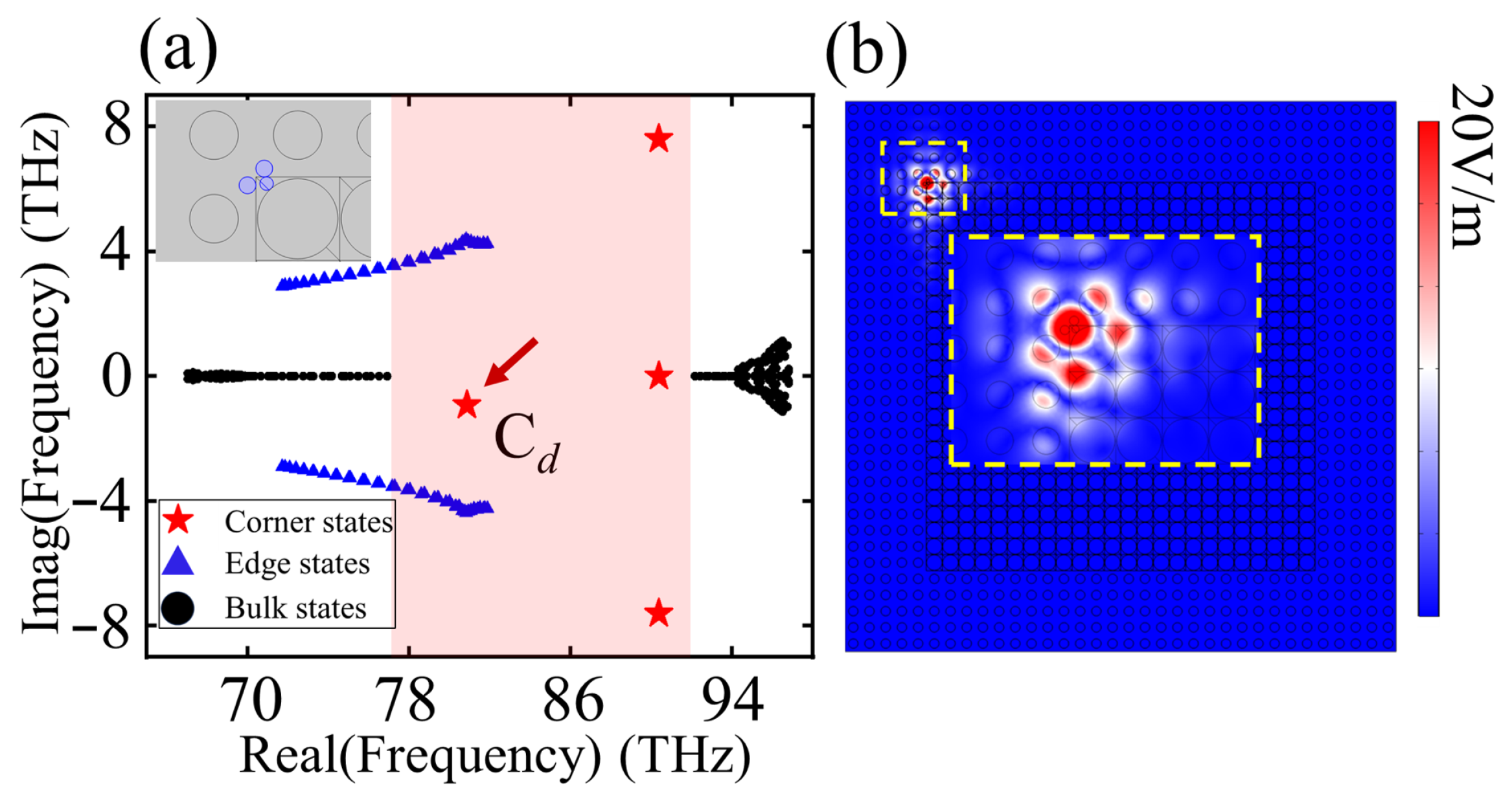
As shown in Figure A2a, the discrete eigenfrequency spectrum corresponds to the illustrated corner-doped supercell, where three circular dielectric rods with a relative permittivity of 12 and radii around 0.1 a were introduced near the corner. The corner state affected by doping (labeled C d ) shifts leftward within the bandgap while maintaining its spectral isolation. This state continues to exhibit strong field localization, as demonstrated by its electric field profile in Figure A2b. These results confirm the remarkable robustness of the second-order corner states in our proposed system.
Figure A2. (a) Eigenfrequency spectrum under corner doping, with insets showing the doping configuration in the corner. The arrow denotes the corner state C d localized at the site of the doped dielectric rod. (b) | E | of C d , with insethighlighted by yellow dotted boxes enhanced field localization at the corner.
Photonics 12 01087 g0a2
As observed in Figure A2a, the corner doping configuration exhibits negligible influence on the eigenfrequency spectrum of bulk states, indicating equally minimal impact on their electric field distributions. To further verify the stability of the NHSE, we constructed a bulk-doped model as shown in Figure A3a. In this model, a 2 × 2 cluster of UCs A, where the bulk states are localized due to the skin effect, was replaced by UCs B, with structural details provided in the inset.
The discrete eigenfrequency spectrum of this system is shown in Figure A3b. Compared with Figure 2c, the overall spectral structure shows no significant changes, exhibiting only minor shifts in the bulk states and the introduction of two edge state shifts due to doping (edge states fall outside the scope of this study and are thus disregarded). Correspondingly, the NHSE remains robust; Figure A3c–f display the electric field distributions of four randomly selected bulk states, all demonstrating a pronounced NHSE. In some field profiles, the absence of electric field within the doped region occurs because the corresponding eigenfrequencies fall within the bandgap of the Hermitian PC used to form the doping unit, leading to field suppression in that area.
Figure A3. (a) Bulk-doped supercell, with an inset showing a detailed view of the doping configuration(yellow dotted box) and the blue dots denote the doped UCs B. (b) Eigenfrequency spectrum under bulk doping. The inset depicts the degeneracy of corner states. (cf) Mode field distributions of four randomly selected bulk states B 1 B 4 , all exhibiting NHSEs. While the field distributions may be suppressed at the doped region due to the bandgap of the Hermitian PC, it remains unaffected elsewhere. (c) B 1 : 74.16 THz. (d) B 2 : 70.388 THz. (e) B 3 : 92.158 THz. (f) B 4 : 92.736 THz.
Photonics 12 01087 g0a3

Appendix C. Simulation Procedures and Details

This section provides a comprehensive description of the simulation procedures and technical details employed in this study. All geometric and material parameters have been specified in preceding sections. The focus here is on the configuration of periodic boundary conditions, parameter sweep setups, meshing strategies, and solver settings within COMSOL Multiphysics. All simulation results exclusively consider the out-of-plane vector component. The formulas presented in the following content are exclusively used for system configuration parameters and are independent of the predefined parameters in the main text.
In the Wave Optics Module, select the Frequency Domain interface and the Eigenfrequency study to access the simulation environment used in this work. To configure the PBCs for calculating the PC band structure, add a Periodic Condition feature in the physics settings and select the corresponding boundary pairs in the system. This allows the PC modeling to be performed on a single UC by applying PCs to all surrounding boundaries. It is particularly important to note that the Brillouin zone scanning path along high-symmetry points shown in Figure 1b,d can be implemented in the parameter settings using a piecewise function. The specific scanning path is defined as follows: k x = i f ( k < 1 , ( 1 k ) p i / a k , i f ( k < 2 , ( k 1 ) p i / a k , p i / a k ) ) and k y = i f ( k < 1 , ( 1 k ) p i / a k , i f ( k < 2 , 0 , ( k 2 ) p i / a k ) ) . In addition, add a P a r a m e t e r S w e e p step to the study, setting the parameter k to sweep from 0 to 3, to obtain the band structure along the specified scanning path.
For the supercell simulations (Figure 2 and Appendix A and Appendix B), the mesh was set to P h y s i c s c o n t r o l l e d m e s h (Fine), which provides sufficient resolution, particularly at material interfaces. The eigenfrequency solver was configured to search for 350 eigenvalues around 67 THz, determined from the band structure and supercell size in Figure 2b.

References

  1. Joannopoulos, J.D.; Villeneuve, P.R.; Fan, S. Photonic crystals: Putting a new twist on light. Nature 1997, 386, 143–149. [Google Scholar] [CrossRef]
  2. Knight, J.C. Photonic crystal fibres. Nature 2003, 424, 847–851. [Google Scholar] [CrossRef]
  3. Rechtsman, M.C.; Zeuner, J.M.; Plotnik, Y.; Lumer, Y.; Podolsky, D.; Dreisow, F.; Nolte, S.; Segev, M.; Szameit, A. Photonic Floquet topological insulators. Nature 2013, 496, 196–200. [Google Scholar] [CrossRef]
  4. Siroki, G.; Huidobro, P.A.; Giannini, V. Topological photonics: From crystals to particles. Phys. Rev. B 2017, 96, 041408. [Google Scholar] [CrossRef]
  5. Midya, B.; Feng, L. Topological multiband photonic superlattices. Phys. Rev. A 2018, 98, 043838. [Google Scholar] [CrossRef]
  6. Ozawa, T.; Price, H.M.; Amo, A.; Goldman, N.; Hafezi, M.; Lu, L.; Rechtsman, M.C.; Schuster, D.; Simon, J.; Zilberberg, O.; et al. Topological photonics. Rev. Mod. Phys. 2019, 91, 015006. [Google Scholar] [CrossRef]
  7. Wang, H.; Gupta, S.K.; Xie, B.; Lu, M. Topological photonic crystals: A review. Front. Optoelectron. 2020, 13, 50–72. [Google Scholar] [CrossRef]
  8. Kim, M.; Jacob, Z.; Rho, J. Recent advances in 2D, 3D and higher-order topological photonics. Light Sci. Appl. 2020, 9, 130. [Google Scholar] [CrossRef] [PubMed]
  9. Chen, Y.; Lan, Z.; Su, Z.; Zhu, J. Inverse design of photonic and phononic topological insulators: A review. Nanophotonics 2022, 11, 4347–4362. [Google Scholar] [CrossRef]
  10. Jalali Mehrabad, M.; Mittal, S.; Hafezi, M. Topological photonics: Fundamental concepts, recent developments, and future directions. Phys. Rev. A 2023, 108, 040101. [Google Scholar] [CrossRef]
  11. Khanikaev, A.B.; Alù, A. Topological photonics: Robustness and nature. Nat. Commun. 2024, 15, 931. [Google Scholar] [CrossRef]
  12. Tang, G.J.; He, X.T.; Shi, F.L.; Liu, J.W.; Chen, X.D.; Dong, J.W. Topological Photonic Crystals: Physics, Designs, and Applications. Laser Photonics Rev. 2022, 16, 2100300. [Google Scholar] [CrossRef]
  13. Butt, M.A.; Khonina, S.N. Recent Advances in Photonic Crystal and Optical Devices. Crystals 2024, 14, 543. [Google Scholar] [CrossRef]
  14. Singhal, A.; Paprotny, I. Slow-Light Enhanced Liquid and Gas Sensing Using 2-D Photonic Crystal Line Waveguides—A Review. IEEE Sens. J. 2022, 22, 20126–20137. [Google Scholar] [CrossRef]
  15. Maleki, M.J.; Soroosh, M.; Parandin, F.; Haddadan, F. Photonic Crystal-Based Decoders: Ideas and Structures. In Recent Advances and Trends in Photonic Crystal Technology; Goyal, A.K., Kumar, A., Eds.; IntechOpen: London, UK, 2023; Chapter 5. [Google Scholar] [CrossRef]
  16. Starczewska, A.; Kępińska, M. Photonic Crystal Structures for Photovoltaic Applications. Materials 2024, 17, 1196. [Google Scholar] [CrossRef] [PubMed]
  17. Leykam, D.; Flach, S. Perspective: Photonic flatbands. APL Photonics 2018, 3, 70901. [Google Scholar] [CrossRef]
  18. Dong, K.; Zhang, T.; Li, J.; Wang, Q.; Yang, F.; Rho, Y.; Wang, D.; Grigoropoulos, C.P.; Wu, J.; Yao, J. Flat Bands in Magic-Angle Bilayer Photonic Crystals at Small Twists. Phys. Rev. Lett. 2021, 126, 223601. [Google Scholar] [CrossRef]
  19. Lu, L.; Fu, L.; Joannopoulos, J.D.; Soljačić, M. Weyl points and line nodes in gyroid photonic crystals. Nat. Photonics 2013, 7, 294–299. [Google Scholar] [CrossRef]
  20. Chen, W.J.; Xiao, M.; Chan, C.T. Photonic crystals possessing multiple Weyl points and the experimental observation of robust surface states. Nat. Commun. 2016, 7, 13038. [Google Scholar] [CrossRef]
  21. Wang, D.; Yang, B.; Gao, W.; Jia, H.; Yang, Q.; Chen, X.; Wei, M.; Liu, C.; Navarro-Cía, M.; Han, J.; et al. Photonic Weyl points due to broken time-reversal symmetry in magnetized semiconductor. Nat. Phys. 2019, 15, 1150–1155. [Google Scholar] [CrossRef]
  22. Pan, Y.; Cui, C.; Chen, Q.; Chen, F.; Zhang, L.; Ren, Y.; Han, N.; Li, W.; Li, X.; Yu, Z.M.; et al. Real higher-order Weyl photonic crystal. Nat. Commun. 2023, 14, 6636. [Google Scholar] [CrossRef] [PubMed]
  23. Wang, H.; Xu, W.; Wei, Z.; Wang, Y.; Wang, Z.; Cheng, X.; Guo, Q.; Shi, J.; Zhu, Z.; Yang, B. Twisted photonic Weyl meta-crystals and aperiodic Fermi arc scattering. Nat. Commun. 2024, 15, 2440. [Google Scholar] [CrossRef]
  24. Abrashuly, A.; Guo, C.; Papadakis, G.T.; Catrysse, P.B.; Fan, S. Weyl points in a twisted multilayer photonic system. Appl. Phys. Lett. 2024, 125, 171703. [Google Scholar] [CrossRef]
  25. Deng, W.; Lu, J.; Li, F.; Huang, X.; Yan, M.; Ma, J.; Liu, Z. Nodal rings and drumhead surface states in phononic crystals. Nat. Commun. 2019, 10, 1769. [Google Scholar] [CrossRef] [PubMed]
  26. Deng, W.M.; Chen, Z.M.; Li, M.Y.; Guo, C.H.; Tian, Z.T.; Sun, K.X.; Chen, X.D.; Chen, W.J.; Dong, J.W. Ideal nodal rings of one-dimensional photonic crystals in the visible region. Light Sci. Appl. 2022, 11, 134. [Google Scholar] [CrossRef]
  27. He, L.; Addison, Z.; Mele, E.J.; Zhen, B. Quadrupole topological photonic crystals. Nat. Commun. 2020, 11, 3119. [Google Scholar] [CrossRef]
  28. Proctor, M.; Huidobro, P.A.; Bradlyn, B.; de Paz, M.B.; Vergniory, M.G.; Bercioux, D.; García-Etxarri, A. Robustness of topological corner modes in photonic crystals. Phys. Rev. Res. 2020, 2, 042038. [Google Scholar] [CrossRef]
  29. Xie, B.; Su, G.; Wang, H.F.; Liu, F.; Hu, L.; Yu, S.Y.; Zhan, P.; Lu, M.H.; Wang, Z.; Chen, Y.F. Higher-order quantum spin Hall effect in a photonic crystal. Nat. Commun. 2020, 11, 3768. [Google Scholar] [CrossRef]
  30. Phan, H.T.; Liu, F.; Wakabayashi, K. Valley-dependent corner states in honeycomb photonic crystals without inversion symmetry. Opt. Express 2021, 29, 18277–18290. [Google Scholar] [CrossRef]
  31. Peng, Y.; Liu, E.; Yan, B.; Xie, J.; Shi, A.; Peng, P.; Li, H.; Liu, J. Higher-order topological states in two-dimensional Stampfli-Triangle photonic crystals. Opt. Lett. 2022, 47, 3011–3014. [Google Scholar] [CrossRef]
  32. Wang, Z.; Liu, D.; Teo, H.T.; Wang, Q.; Xue, H.; Zhang, B. Higher-order Dirac semimetal in a photonic crystal. Phys. Rev. B 2022, 105, L060101. [Google Scholar] [CrossRef]
  33. Wang, Y.; Wang, H.X.; Liang, L.; Zhu, W.; Fan, L.; Lin, Z.K.; Li, F.; Zhang, X.; Luan, P.G.; Poo, Y.; et al. Hybrid topological photonic crystals. Nat. Commun. 2023, 14, 4457. [Google Scholar] [CrossRef] [PubMed]
  34. Liu, X.Y.; Liu, Y.; Xiong, Z.; Wang, H.X.; Jiang, J.H. Higher-order topological phases in bilayer phononic crystals and topological bound states in the continuum. Phys. Rev. B 2024, 109, 205137. [Google Scholar] [CrossRef]
  35. Wang, Z.; Meng, Y.; Yan, B.; Zhao, D.; Yang, L.; Chen, J.; Cheng, M.; Xiao, T.; Shum, P.P.; Liu, G.G.; et al. Realization of a three-dimensional photonic higher-order topological insulator. Nat. Commun. 2025, 16, 3122. [Google Scholar] [CrossRef]
  36. Medina-Vázquez, J.A.; González-Ramírez, E.Y. Higher-order hybrid adiabatic topological states in photonic crystals. Phys. Rev. B 2025, 111, L020101. [Google Scholar] [CrossRef]
  37. Xie, B.Y.; Wang, H.F.; Wang, H.X.; Zhu, X.Y.; Jiang, J.H.; Lu, M.H.; Chen, Y.F. Second-order photonic topological insulator with corner states. Phys. Rev. B 2018, 98, 205147. [Google Scholar] [CrossRef]
  38. Zhou, X.; Lin, Z.K.; Lu, W.; Lai, Y.; Hou, B.; Jiang, J.H. Twisted Quadrupole Topological Photonic Crystals. Laser Photonics Rev. 2020, 14, 2000010. [Google Scholar] [CrossRef]
  39. Zhang, L.; Yang, Y.; Lin, Z.K.; Qin, P.; Chen, Q.; Gao, F.; Li, E.; Jiang, J.H.; Zhang, B.; Chen, H. Higher-Order Topological States in Surface-Wave Photonic Crystals. Adv. Sci. 2020, 7, 1902724. [Google Scholar] [CrossRef]
  40. Gong, R.; Zhang, M.; Li, H.; Lan, Z. Topological photonic crystal fibers based on second-order corner modes. Opt. Lett. 2021, 46, 3849–3852. [Google Scholar] [CrossRef]
  41. Jin, M.C.; Gao, Y.F.; Lin, H.Z.; He, Y.H.; Chen, M.Y. Corner states in second-order two-dimensional topological photonic crystals with reversed materials. Phys. Rev. A 2022, 106, 013510. [Google Scholar] [CrossRef]
  42. Chen, Y.; Lan, Z.; Zhu, J. Second-order topological phases in C 4v -symmetric photonic crystals beyond the two-dimensional Su-Schrieffer–Heeger model. Nanophotonics 2022, 11, 1345–1354. [Google Scholar] [CrossRef]
  43. Shao, S.; Liang, L.; Hu, J.H.; Poo, Y.; Wang, H.X. Topological edge and corner states in honeycomb-kagome photonic crystals. Opt. Express 2023, 31, 17695–17708. [Google Scholar] [CrossRef]
  44. Li, M.; Zhirihin, D.; Gorlach, M.; Ni, X.; Filonov, D.; Slobozhanyuk, A.; Alù, A.; Khanikaev, A.B. Higher-order topological states in photonic kagome crystals with long-range interactions. Nat. Photonics 2020, 14, 89–94. [Google Scholar] [CrossRef]
  45. Hawary, F.; Boisson, G.; Guillemot, C.; Guillotel, P. Compressively sampled light field reconstruction using orthogonal frequency selection and refinement. Signal Process. Image Commun. 2021, 92, 116087. [Google Scholar] [CrossRef]
  46. Min, L.; Sun, H.; Guo, L.; Wang, M.; Cao, F.; Zhong, J.; Li, L. Frequency-selective perovskite photodetector for anti-interference optical communications. Nat. Commun. 2024, 15, 2066. [Google Scholar] [CrossRef]
  47. Wang, Z.; Chong, Y.; Joannopoulos, J.D.; Soljačić, M. Observation of unidirectional backscattering-immune topological electromagnetic states. Nature 2009, 461, 772–775. [Google Scholar] [CrossRef] [PubMed]
  48. Kim, M.; Rho, J. Quantum Hall phase and chiral edge states simulated by a coupled dipole method. Phys. Rev. B 2020, 101, 195105. [Google Scholar] [CrossRef]
  49. Barczyk, R.; Kuipers, L.; Verhagen, E. Observation of Landau levels and chiral edge states in photonic crystals through pseudomagnetic fields induced by synthetic strain. Nat. Photonics 2024, 18, 574–579. [Google Scholar] [CrossRef]
  50. Parappurath, N.; Alpeggiani, F.; Kuipers, L.; Verhagen, E. Direct observation of topological edge states in silicon photonic crystals: Spin, dispersion, and chiral routing. Sci. Adv. 2025, 6, eaaw4137. [Google Scholar] [CrossRef]
  51. Xi, R.; Chen, Q.; Yan, Q.; Zhang, L.; Chen, F.; Li, Y.; Chen, H.; Yang, Y. Topological Chiral Edge States in Deep-Subwavelength Valley Photonic Metamaterials. Laser Photonics Rev. 2022, 16, 2200194. [Google Scholar] [CrossRef]
  52. Han, J.; Liang, F.; Zhao, Y.; Liu, J.; Wang, S.; Wang, X.; Zhao, D.; Wang, B.Z. Valley kink states and valley-polarized chiral edge states in substrate-integrated topological photonic crystals. Phys. Rev. Appl. 2024, 21, 014046. [Google Scholar] [CrossRef]
  53. Molesky, S.; Lin, Z.; Piggott, A.Y.; Jin, W.; Vucković, J.; Rodriguez, A.W. Inverse design in nanophotonics. Nat. Photonics 2018, 12, 659–670. [Google Scholar] [CrossRef]
  54. Sounas, D.L.; Alù, A. Non-reciprocal photonics based on time modulation. Nat. Photonics 2017, 11, 774–783. [Google Scholar] [CrossRef]
  55. Nejad, S.M.H.A.; Seyyed Fakhrabadi, M.M. Symmetry breaking and nonreciprocity in nonlinear phononic crystals: Inspiration from atomic interactions. Mech. Mater. 2025, 201, 105231. [Google Scholar] [CrossRef]
  56. Li, H.; Chen, Q.; Ouyang, Q.; Zhao, J. Fabricating a Novel Raman Spectroscopy-Based Aptasensor for Rapidly Sensing Salmonella typhimurium. Food Anal. Methods 2017, 10, 3032–3041. [Google Scholar] [CrossRef]
  57. Liu, Y.; Ouyang, Q.; Li, H.; Chen, M.; Zhang, Z.; Chen, Q. Turn-On Fluoresence Sensor for Hg2+ in Food Based on FRET between Aptamers-Functionalized Upconversion Nanoparticles and Gold Nanoparticles. J. Agric. Food Chem. 2018, 66, 6188–6195. [Google Scholar] [CrossRef] [PubMed]
  58. Zhang, X.; Huang, C.; Jiang, Y.; Jiang, Y.; Shen, J.; Han, E. Structure-Switching Electrochemical Aptasensor for Single-Step and Specific Detection of Trace Mercury in Dairy Products. J. Agric. Food Chem. 2018, 66, 10106–10112. [Google Scholar] [CrossRef]
  59. Duan, N.; Chang, B.; Zhang, H.; Wang, Z.; Wu, S. Salmonella typhimurium detection using a surface-enhanced Raman scattering-based aptasensor. Int. J. Food Microbiol. 2016, 218, 38–43. [Google Scholar] [CrossRef] [PubMed]
  60. Yan, T.; Zhu, H.; Sun, L.; Wang, X.; Ling, P. Investigation of an Experimental Laser Sensor-Guided Spray Control System for Greenhouse Variable-Rate Applications. Trans. ASABE 2019, 62, 899–911. [Google Scholar] [CrossRef]
  61. Han, F.; Huang, X.; Teye, E. Novel prediction of heavy metal residues in fish using a low-cost optical electronic tongue system based on colorimetric sensors array. J. Food Process Eng. 2019, 42, e12983. [Google Scholar] [CrossRef]
  62. Luo, L.; Ma, S.; Li, L.; Liu, X.; Zhang, J.; Li, X.; Liu, D.; You, T. Monitoring zearalenone in corn flour utilizing novel self-enhanced electrochemiluminescence aptasensor based on NGQDs-NH2-Ru@SiO2 luminophore. Food Chem. 2019, 292, 98–105. [Google Scholar] [CrossRef]
  63. Wang, P.; Li, H.; Hassan, M.M.; Guo, Z.; Zhang, Z.Z.; Chen, Q. Fabricating an Acetylcholinesterase Modulated UCNPs-Cu2+ Fluorescence Biosensor for Ultrasensitive Detection of Organophosphorus Pesticides-Diazinon in Food. J. Agric. Food Chem. 2019, 67, 4071–4079. [Google Scholar] [CrossRef]
  64. Xu, Y.; Zhang, W.; Shi, J.; Li, Z.; Huang, X.; Zou, X.; Tan, W.; Zhang, X.; Hu, X.; Wang, X.; et al. Impedimetric aptasensor based on highly porous gold for sensitive detection of acetamiprid in fruits and vegetables. Food Chem. 2020, 322, 126762. [Google Scholar] [CrossRef]
  65. Liang, N.; Hu, X.; Li, W.; Mwakosya, A.W.; Guo, Z.; Xu, Y.; Huang, X.; Li, Z.; Zhang, X.; Zou, X.; et al. Fluorescence and colorimetric dual-mode sensor for visual detection of malathion in cabbage based on carbon quantum dots and gold nanoparticles. Food Chem. 2021, 343, 128494. [Google Scholar] [CrossRef]
  66. Sun, Y.; Zhang, N.; Han, C.; Chen, Z.; Zhai, X.; Li, Z.; Zheng, K.; Zhu, J.; Wang, X.; Zou, X.; et al. Competitive immunosensor for sensitive and optical anti-interference detection of imidacloprid by surface-enhanced Raman scattering. Food Chem. 2021, 358, 129898. [Google Scholar] [CrossRef]
  67. Sharma, A.S.; Ali, S.; Sabarinathan, D.; Murugavelu, M.; Li, H.; Chen, Q. Recent progress on graphene quantum dots-based fluorescence sensors for food safety and quality assessment applications. Compr. Rev. Food Sci. Food Saf. 2021, 20, 5765–5801. [Google Scholar] [CrossRef]
  68. Jiang, H.; Lin, H.; Lin, J.; Yao-Say Solomon Adade, S.; Chen, Q.; Xue, Z.; Chan, C. Non-destructive detection of multi-component heavy metals in corn oil using nano-modified colorimetric sensor combined with near-infrared spectroscopy. Food Control 2022, 133, 108640. [Google Scholar] [CrossRef]
  69. Bi, X.; Li, L.; Luo, L.; Liu, X.; Li, J.; You, T. A ratiometric fluorescence aptasensor based on photoinduced electron transfer from CdTe QDs to WS2 NTs for the sensitive detection of zearalenone in cereal crops. Food Chem. 2022, 385, 132657. [Google Scholar] [CrossRef] [PubMed]
  70. Mao, H.; Du, X.; Yan, Y.; Zhang, X.; Ma, G.; Wang, Y.; Liu, Y.; Wang, B.; Yang, X.; Shi, Q. Highly sensitive detection of daminozide using terahertz metamaterial sensors. Int. J. Agric. Biol. Eng. 2022, 15, 180–188. [Google Scholar] [CrossRef]
  71. Liu, N.; Zhang, W.; Liu, F.; Zhang, M.; Du, C.; Sun, C.; Cao, J.; Ji, S.; Sun, H. Development of a Crop Spectral Reflectance Sensor. Agronomy 2022, 12, 2139. [Google Scholar] [CrossRef]
  72. Barimah, A.O.; Chen, P.; Yin, L.; El-Seedi, H.R.; Zou, X.; Guo, Z. SERS nanosensor of 3-aminobenzeneboronic acid labeled Ag for detecting total arsenic in black tea combined with chemometric algorithms. J. Food Compos. Anal. 2022, 110, 104588. [Google Scholar] [CrossRef]
  73. Hassan, M.M.; Xu, Y.; Zareef, M.; Li, H.; Rong, Y.; Chen, Q. Recent advances of nanomaterial-based optical sensor for the detection of benzimidazole fungicides in food: A review. Crit. Rev. Food Sci. Nutr. 2023, 63, 2851–2872. [Google Scholar] [CrossRef]
  74. Xu, Y.; Hassan, M.M.; Sharma, A.S.; Li, H.; Chen, Q. Recent advancement in nano-optical strategies for detection of pathogenic bacteria and their metabolites in food safety. Crit. Rev. Food Sci. Nutr. 2023, 63, 486–504. [Google Scholar] [CrossRef]
  75. Li, M.; Qiu, Y.; Liu, G.; Xiao, Y.; Tian, Y.; Fang, S. Plasmonic colorimetry and G-quadruplex fluorescence-based aptasensor: A dual-mode, protein-free and label-free detection for OTA. Food Chem. 2024, 448, 139115. [Google Scholar] [CrossRef] [PubMed]
  76. Zhang, L.; Chen, M.; Duan, H.; Bu, Q.; Dong, X. Recent advances of optical sensors for point-of-care detection of phthalic acid esters. Front. Sustain. Food Syst. 2024, 8, 1474831. [Google Scholar]
  77. Yao, S.; Wang, Z. Edge States and Topological Invariants of Non-Hermitian Systems. Phys. Rev. Lett. 2018, 121, 086803. [Google Scholar] [CrossRef]
  78. Yao, S.; Song, F.; Wang, Z. Non-Hermitian Chern Bands. Phys. Rev. Lett. 2018, 121, 136802. [Google Scholar] [CrossRef]
  79. Shen, H.; Zhen, B.; Fu, L. Topological Band Theory for Non-Hermitian Hamiltonians. Phys. Rev. Lett. 2018, 120, 146402. [Google Scholar] [CrossRef] [PubMed]
  80. Kunst, F.K.; Edvardsson, E.; Budich, J.C.; Bergholtz, E.J. Biorthogonal Bulk-Boundary Correspondence in Non-Hermitian Systems. Phys. Rev. Lett. 2018, 121, 026808. [Google Scholar] [CrossRef] [PubMed]
  81. Yokomizo, K.; Murakami, S. Non-Bloch Band Theory of Non-Hermitian Systems. Phys. Rev. Lett. 2019, 123, 066404. [Google Scholar] [CrossRef]
  82. Jin, L.; Song, Z. Bulk-boundary correspondence in a non-Hermitian system in one dimension with chiral inversion symmetry. Phys. Rev. B 2019, 99, 081103. [Google Scholar] [CrossRef]
  83. Yang, X.; Cao, Y.; Zhai, Y. Non-Hermitian Weyl semimetals: Non-Hermitian skin effect and non-Bloch bulk boundary correspondence. Chin. Phys. B 2022, 31, 010308. [Google Scholar] [CrossRef]
  84. Yang, Z.; Zhang, K.; Fang, C.; Hu, J. Non-Hermitian Bulk-Boundary Correspondence and Auxiliary Generalized Brillouin Zone Theory. Phys. Rev. Lett. 2020, 125, 226402. [Google Scholar] [CrossRef]
  85. Cao, Y.; Li, Y.; Yang, X. Non-Hermitian bulk-boundary correspondence in a periodically driven system. Phys. Rev. B 2021, 103, 075126. [Google Scholar] [CrossRef]
  86. Li, Y.; Cao, Y.; Chen, Y.; Yang, X. Universal Characteristics of One-Dimensional Non-Hermitian Superconductors. J. Phys. Condens. Matter 2023, 35, 055401. [Google Scholar] [CrossRef]
  87. Li, Y.; Liang, C.; Wang, C.; Lu, C.; Liu, Y.C. Gain-Loss-Induced Hybrid Skin-Topological Effect. Phys. Rev. Lett. 2022, 128, 223903. [Google Scholar] [CrossRef]
  88. Li, Y.; Ji, X.; Chen, Y.; Yan, X.; Yang, X. Topological energy braiding of non-Bloch bands. Phys. Rev. B 2022, 106, 195425. [Google Scholar] [CrossRef]
  89. Zhang, X.; Zhang, T.; Lu, M.H.; Chen, Y.F. A review on non-Hermitian skin effect. Adv. Phys. X 2022, 7, 2109431. [Google Scholar] [CrossRef]
  90. Ji, X.; Yang, X. Generalized Bulk-Boundary Correspondence in Periodically Driven Non-Hermitian Systems. J. Phys. Condens. Matter 2024, 36, 243001. [Google Scholar] [CrossRef] [PubMed]
  91. Tong, X.; Zhang, Y.; Li, B.; Yang, X. Impact of nonreciprocal hopping on localization in non-Hermitian quasiperiodic systems. Phys. Rev. B 2025, 111, 214202. [Google Scholar] [CrossRef]
  92. Ji, X.; Geng, H.; Akhtar, N.; Yang, X. Floquet engineering of point-gapped topological superconductors. Phys. Rev. B 2025, 111, 195419. [Google Scholar] [CrossRef]
  93. Shi, A.; Peng, Y.; Peng, P.; Chen, J.; Liu, J. Delocalization of higher-order topological states in higher-dimensional non-Hermitian quasicrystals. Phys. Rev. B 2024, 110, 014106. [Google Scholar] [CrossRef]
  94. Chen, J.; Shi, A.; Peng, Y.; Peng, P.; Liu, J. Hybrid Skin-Topological Effect Induced by Eight-Site Cells and Arbitrary Adjustment of the Localization of Topological Edge States. Chin. Phys. Lett. 2024, 41, 037103. [Google Scholar] [CrossRef]
  95. Ji, X.; Ding, W.; Chen, Y.; Yang, X. Non-Hermitian second-order topological superconductors. Phys. Rev. B 2024, 109, 125420. [Google Scholar] [CrossRef]
  96. Liang, H.Q.; Ou, Z.; Li, L.; Xu, G.F. Intrinsic perturbation induced anomalous higher-order boundary states in non-Hermitian systems. Phys. Rev. B 2025, 111, L241112. [Google Scholar] [CrossRef]
  97. Zhao, E.; Wang, Z.; He, C.; Poon, T.F.J.; Pak, K.K.; Liu, Y.J.; Ren, P.; Liu, X.J.; Jo, G.B. Two-dimensional non-Hermitian skin effect in an ultracold Fermi gas. Nature 2025, 637, 565–573. [Google Scholar] [CrossRef]
  98. Peng, Y.; Shi, A.; Peng, P.; Liu, J. Pseudospin-induced asymmetric field in non-Hermitian photonic crystals with multiple topological transitions. Phys. Rev. B 2025, 111, 085148. [Google Scholar] [CrossRef]
  99. Shi, A.; Bao, L.; Peng, P.; Ning, J.; Wang, Z.; Liu, J. Non-Hermitian Floquet higher-order topological states in two-dimensional quasicrystals. Phys. Rev. B 2025, 111, 094109. [Google Scholar] [CrossRef]
  100. Gong, Z.; Ashida, Y.; Kawabata, K.; Takasan, K.; Higashikawa, S.; Ueda, M. Topological Phases of Non-Hermitian Systems. Phys. Rev. X 2018, 8, 031079. [Google Scholar] [CrossRef]
  101. Liu, T.; Zhang, Y.R.; Ai, Q.; Gong, Z.; Kawabata, K.; Ueda, M.; Nori, F. Second-Order Topological Phases in Non-Hermitian Systems. Phys. Rev. Lett. 2019, 122, 076801. [Google Scholar] [CrossRef]
  102. Song, F.; Yao, S.; Wang, Z. Non-Hermitian Topological Invariants in Real Space. Phys. Rev. Lett. 2019, 123, 246801. [Google Scholar] [CrossRef]
  103. Luo, X.W.; Zhang, C. Higher-Order Topological Corner States Induced by Gain and Loss. Phys. Rev. Lett. 2019, 123, 073601. [Google Scholar] [CrossRef]
  104. Zeng, Q.B.; Yang, Y.B.; Xu, Y. Topological phases in non-Hermitian Aubry-André-Harper models. Phys. Rev. B 2020, 101, 020201. [Google Scholar] [CrossRef]
  105. Ghosh, A.K.; Nag, T. Non-Hermitian higher-order topological superconductors in two dimensions: Statics and dynamics. Phys. Rev. B 2022, 106, L140303. [Google Scholar] [CrossRef]
  106. Schomerus, H.; Wiersig, J. Non-Hermitian-transport effects in coupled-resonator optical waveguides. Phys. Rev. A 2014, 90, 053819. [Google Scholar] [CrossRef]
  107. Malzard, S.; Schomerus, H. Bulk and edge-state arcs in non-Hermitian coupled-resonator arrays. Phys. Rev. A 2018, 98, 033807. [Google Scholar] [CrossRef]
  108. Ao, Y.; Hu, X.; You, Y.; Lu, C.; Fu, Y.; Wang, X.; Gong, Q. Topological Phase Transition in the Non-Hermitian Coupled Resonator Array. Phys. Rev. Lett. 2020, 125, 013902. [Google Scholar] [CrossRef] [PubMed]
  109. Song, Y.; Liu, W.; Zheng, L.; Zhang, Y.; Wang, B.; Lu, P. Two-dimensional non-Hermitian Skin Effect in a Synthetic Photonic Lattice. Phys. Rev. Appl. 2020, 14, 064076. [Google Scholar] [CrossRef]
  110. Zhu, X.; Wang, H.; Gupta, S.K.; Zhang, H.; Xie, B.; Lu, M.; Chen, Y. Photonic non-Hermitian skin effect and non-Bloch bulk-boundary correspondence. Phys. Rev. Res. 2020, 2, 013280. [Google Scholar] [CrossRef]
  111. Feng, L.; El-Ganainy, R.; Ge, L. Non-Hermitian photonics based on parity–time symmetry. Nat. Photonics 2017, 11, 752–762. [Google Scholar] [CrossRef]
  112. Feng, Y.; Liu, Z.; Liu, F.; Yu, J.; Liang, S.; Li, F.; Zhang, Y.; Xiao, M.; Zhang, Z. Loss Difference Induced Localization in a Non-Hermitian Honeycomb Photonic Lattice. Phys. Rev. Lett. 2023, 131, 013802. [Google Scholar] [CrossRef]
  113. Lafalce, E.; Zeng, Q.; Lin, C.H.; Smith, M.J.; Malak, S.T.; Jung, J.; Yoon, Y.J.; Lin, Z.; Tsukruk, V.V.; Vardeny, Z.V. Robust lasing modes in coupled colloidal quantum dot microdisk pairs using a non-Hermitian exceptional point. Nat. Commun. 2019, 10, 561. [Google Scholar] [CrossRef]
  114. Król, M.; Septembre, I.; Oliwa, P.; Kȩdziora, M.; Łempicka-Mirek, K.; Muszyński, M.; Mazur, R.; Morawiak, P.; Piecek, W.; Kula, P.; et al. Annihilation of exceptional points from different Dirac valleys in a 2D photonic system. Nat. Commun. 2022, 13, 5340. [Google Scholar] [CrossRef]
  115. Li, A.; Wei, H.; Cotrufo, M.; Chen, W.; Mann, S.; Ni, X.; Xu, B.; Chen, J.; Wang, J.; Fan, S.; et al. Exceptional points and non-Hermitian photonics at the nanoscale. Nat. Nanotechnol. 2023, 18, 706–720. [Google Scholar] [CrossRef]
  116. Zhu, W.; Gong, J. Photonic corner skin modes in non-Hermitian photonic crystals. Phys. Rev. B 2023, 108, 035406. [Google Scholar] [CrossRef]
  117. Zheng, X.; Jalali Mehrabad, M.; Vannucci, J.; Li, K.; Dutt, A.; Hafezi, M.; Mittal, S.; Waks, E. Dynamic control of 2D non-Hermitian photonic corner skin modes in synthetic dimensions. Nat. Commun. 2024, 15, 10881. [Google Scholar] [CrossRef]
  118. Xiong, L.; Jiang, X.; Hu, G. Scattering singularity in topological dielectric photonic crystals. Phys. Rev. B 2024, 109, 224111. [Google Scholar] [CrossRef]
  119. Rybin, M.V.; Limonov, M.F. Inverse dispersion method for calculation of complex photonic band diagram and PT symmetry. Phys. Rev. B 2016, 93, 165132. [Google Scholar] [CrossRef]
  120. Tan, H. Measurement-Based Control of Quantum Entanglement and Steering in a Distant Magnomechanical System. Photonics 2023, 10, 1081. [Google Scholar] [CrossRef]
  121. Huang, F.; Chen, G.; Zhang, X. Modeling Electronic and Optical Properties of InAs/InP Quantum Dots. Photonics 2024, 11, 749. [Google Scholar] [CrossRef]
Figure 1. (a) The UC of non-Hermitian PC with an air hole radius of R 1 = 0.48 a ; the red (blue) region corresponds to gain (loss). (b) The band structure of PC A under PBCs, with insets showing the E z field component distributions at high-symmetry points( Γ , X , M ). The inset illustrates the first Brillouin zone of the square-lattice PC, indicating the high-symmetry points and the scanning path (red line). (c) The UC of Hermitian PC with a dielectric rod radius of R 2 = 0.29 a . (d) The band structure of PC B under PBCs, with insets depicting the E z field component distributions at high-symmetry points. (e) Frequencies of the first two bands at X point with respect to R 1 , and the bandgap between the two bands is topologically nontrivial. (f) Bandgap with respect to R 1 .
Photonics 12 01087 g001
Figure 2. (a) Schematic illustration of the supercell system composed of UCs, where yellow and gray regions represent UCs A and B, respectively. The inset shows an enlarged view of the UCs’ distribution in one corner. (b,c) Discrete spectra of eigenfrequencies. (b) The solution number–real part of the eigenfrequency spectrum. The real bandgap is indicated with shading. Bulk states, edge states, and corner states are denoted by points, triangles, and stars, respectively. Four corner states are labeled as C 1 C 4 according to their ordering, with the inset illustrating the real parts of eigenfrequencies for these corner states. (c) The real part–imaginary part of the eigenfrequency spectrum. The inset demonstrates the degeneracy of C 3 and C 4 . (dg) Electric field modulus distributions for states C 1 C 4 . (h) Imaginary parts of eigenfrequencies for C 1 and C 2 versus the gain/loss parameter γ .
Photonics 12 01087 g002
Figure 3. (a) The normalized average E of all bulk states, revealing pronounced NHSE. (b) M I P R as a function of the gain/loss parameter γ , demonstrating a strong correlation between the NHSE and the gain/loss parameters.
Photonics 12 01087 g003
Figure 4. (a) Schematic of the system with PBCx-OBCy composed of alternating UCs A and B, where yellow boundaries represent PBCs and black boundaries indicate perfect electric conductor (PEC) boundaries. (b,c) Eigenfrequency spectra: Gray dots represent bulk states, with a selected bulk state highlighted in green. Isolated blue dots denote edge states, with a representative edge state marked in red. Shaded regions emphasize the bandgap. (b) k x –real part of spectrum. (c) Imaginary part–real part of spectrum. (d) Electric field distribution corresponding to the red point, exhibiting characteristic edge state localization. (e) Electric field distribution corresponding to the green point, demonstrating the characteristic NHSE.
Photonics 12 01087 g004
Disclaimer/Publisher’s Note: The statements, opinions and data contained in all publications are solely those of the individual author(s) and contributor(s) and not of MDPI and/or the editor(s). MDPI and/or the editor(s) disclaim responsibility for any injury to people or property resulting from any ideas, methods, instructions or products referred to in the content.