Article

Tunable Filtering via Lossy Mode Resonance in Integrated Photonics

Institute of Solid State Physics, LV-1063 Riga, Latvia
Photonics 2025, 12(11), 1086; https://doi.org/10.3390/photonics12111086
Submission received: 23 September 2025 / Revised: 31 October 2025 / Accepted: 3 November 2025 / Published: 3 November 2025
(This article belongs to the Section Optoelectronics and Optical Materials)

Abstract

This study explores an integrated tunable filter based on lossy mode resonance (LMR) in TiOx thin films, modeled in COMSOL Multiphysics using the Wave Optics and Semiconductor modules. By exploiting the electro-optic (EO) modulation of free carrier concentration in TiOx, the LMR wavelength can be actively tuned under an applied electric field. The results demonstrate a tuning efficiency of 4.0   nm / V , which surpasses many reported EO tunable filters. Optimization studies reveal that thinner ITO electrodes and TiOx layers enhance tuning efficiency, while the initial bulk free carrier concentration has limited influence due to the compensating effect of the Debye length. These findings extend the applicability of LMR beyond sensing, highlighting its potential for active photonic components in integrated optics.

1. Introduction

Lossy mode resonance (LMR) occurs when light travels through an optical fiber or waveguide coated with a thin film whose real permittivity is positive and larger than both its imaginary part and the permittivity of the guiding medium. Under such conditions, attenuation bands appear in the transmission spectrum, originating from the coupling between the guided core modes and the lossy modes of the thin film [1]. These attenuation bands are highly sensitive to external parameters such as temperature [2], pH [3], humidity [4], concentrations of volatile organic compounds [5], and diverse biomolecules [1]. Consequently, LMR has been extensively explored in the context of optical sensing, which to date represents its most established field of application. The relatively recent discovery of LMR at the level of integrated photonic chips, first demonstrated by our group in 2024, opens the possibility of extending this phenomenon beyond sensing and toward novel classes of integrated photonic devices [6].
The LMR phenomenon can be described through a Fabry–Perot interference model, where partial reflections at both interfaces of the lossy thin film create resonant coupling between guided modes [7]. In contrast to surface plasmon resonance (SPR), which occurs only for transverse magnetic (TM) polarization at metal–dielectric interfaces, LMR can be excited with both transverse electric (TE) and TM polarized light and can support multiple resonances. Moreover, it can be realized using a wide range of coating materials, including polymers [3], semiconductors [8], and dielectrics [9], which makes it a versatile and cost-effective approach for integrated photonic applications.
While sensing represents the most extensively studied application of LMR, the phenomenon is not limited to this purpose. With appropriate device design, LMR can also be employed for tunable filtering controlled by an external electric field. In semiconductors with sufficiently high free carrier concentrations, typically exceeding 1019 1/cm3, optical properties in the near-infrared (NIR) region can be strongly influenced by variations in free carrier density, as described by the Drude model [10]. An applied bias alters band bending and shifts conduction or valence bands relative to the Fermi level, thereby modifying the average free carrier concentration in a thin film. This change directly affects the dielectric permittivity of the thin film and consequently tunes the spectral position of the LMR. Such a mechanism provides a foundation for LMR-based tunable filters and may offer higher tuning efficiency compared with many currently available approaches in integrated photonics. It is worth noting that several studies on LMR have also explored electro-optic (EO) behavior. For instance, Ref. [11] showed that electrolytes can act as the external medium, where an applied bias redistributes ions and locally modifies the refractive index. This process induces a measurable LMR shift, but it depends on ion kinetics, which are much slower than electron kinetics. In addition, the electrolyte-based approach in [11] is difficult to integrate into photonic circuits.
Our previous studies have identified polymers as particularly promising materials for integrated LMR devices [6]. Numerical simulations indicated that waveguide dimensions on the order of several tens of micrometers are necessary to observe the phenomenon [12]. For inorganic platforms, such large waveguide dimensions are often impractical to fabricate and may also reduce sensitivity due to their inherently higher refractive indices. Materials with very high refractive indices cannot support LMR excitation because the lossy coating must exhibit a higher refractive index than the waveguide core. In addition, LMR devices are typically designed for broadband operation with tunable or spectral light sources, unlike many high-index integrated photonic platforms optimized for single-wavelength applications. Polymers, in contrast, allow straightforward fabrication of large waveguides while maintaining favorable refractive-index contrast for LMR sensitivity [6]. Among commercially available polymers for photonic applications, OrmoCore photoresist emerges as the most promising candidate, offering compatibility with lithographic patterning and high transparency at datacom wavelengths, with reported propagation losses of 0.2 dB/cm at 1310 nm [13]. OrmoCore has already been widely utilized for integrated photonics devices, including Bragg gratings [14], ring resonators [15], and bimodal interferometers [16], making it a robust platform for the proposed device.
In recent years, several alternative approaches have been explored for achieving tunability in integrated photonic devices. Phase-change materials such as Ge2Sb2Te5 (GST) and Sb2S3 can provide large refractive index contrast upon switching, but they typically require thermal or optical activation, which limits modulation speed and introduces device degradation over repeated cycles [17]. Hybrid plasmonic–photonic structures have also demonstrated strong confinement and tunability, yet their fabrication often involves nanoscale patterning and complex alignment steps that complicate large-area integration [18]. Flat-profile resonant architectures, including microring resonators incorporating photonic crystal structures [19], cascaded silicon nitride microrings with reconfigurable bandwidths [20], and Vernier-coupled microrings [21], offer sharp spectral features and high Q-factors [22]. However, their tuning range is generally restricted by narrow modal overlap and strong dependence on geometric precision. In contrast, the LMR-based approach proposed in this work enables efficient wavelength tuning through modulation of free carriers in TiOx, employing a simple multilayer stack of commonly available materials. This configuration achieves high tuning efficiency without phase-change transitions, thermal activation, or submicron structuring, making it attractive for scalable and low-cost integrated photonic implementations.
This work presents the concept of an integrated LMR-based tunable filter. In contrast to the prevailing focus on sensing applications, the proposed device explores the potential of LMR for non-sensing functionalities in integrated photonics. This study explores several device designs for LMR tuning with an applied external field in the O-band, aiming to demonstrate the feasibility of the concept and determine the most efficient configuration. The results are obtained through finite element method (FEM) simulations performed in COMSOL Multiphysics version 6.3 (COMSOL AB, Stockholm, Sweden), employing both the Wave Optics and Semiconductor modules to model the phenomenon. This research also introduces an alternative approach to LMR sensing by replacing the costly broad-spectrum source and spectrometer with a single-wavelength source and photodetector, achieved by tuning the applied voltage to place the LMR at the desired wavelength. Although the present work focuses on numerical modeling and design optimization, all simulation parameters were obtained from experimentally characterized thin films, and fabrication of the proposed device is currently underway for experimental validation.

2. Materials and Methods

Since the results of this research are intended to be applied in the subsequent fabrication of real devices, it is recommended to use the actual optical properties of the fabricated materials in numerical calculations. Therefore, all materials were fabricated using appropriate tools, and their optical properties were further characterized by spectral ellipsometry. This approach was applied to all fabricated materials, with the exception of commercially available products such as the OrmoCore photoresist (micro resist technology GmbH, Berlin, Germany), whose optical properties are well defined by the manufacturer.

2.1. Materials Fabrication and Characterization

Since the proposed device is based on an electrode–insulator–semiconductor–insulator–electrode architecture, the choice of insulator material is crucial. For this purpose, Al2O3 was selected as a conventional insulating material commonly used in optoelectronics [23]. The Al2O3 layer was deposited onto glass slides (75 × 25 × 1 mm) using a thermal atomic layer deposition system Savannah S100 (Veeco/Cambridge NanoTech, Waltham, MA, USA) with trimethylaluminum and water serving as precursors at a deposition temperature of 150 °C [23]. Prior to deposition, the glass slides were cleaned in an ultrasonic bath with acetone and isopropanol.
Indium tin oxide (ITO) was selected as the electrode material because it is a well-known transparent conductor that is widely used in optoelectronics and LMR applications [24]. Our earlier studies showed that LMR can be observed in ITO-coated devices [25]. In the present structure, the inclusion of ITO electrodes therefore does not suppress the LMR phenomenon but may influence the spectral position of the resonance depending on the electrode thickness. ITO thin films were deposited on glass slides (75 × 25 × 1 mm) by DC magnetron sputtering using the Sidrabe G500M system (Sidrabe, Riga, Latvia). The deposition was performed in Ar plasma at a pressure of 5 mTorr and a power of 200 W with an ITO target composed of In2O3 and SnO2 in a weight ratio of 9:1 (100 × 200 × 9 mm). Before deposition the glass substrates were cleaned in an ultrasonic bath with acetone and isopropanol.
Non-stoichiometric TiOx was chosen as the primary material for LMR generation and tuning under an external electric field. Previous studies demonstrated that LMR can be experimentally observed in TiOx thin films [25]. Since tuning mechanism depends on free carrier concentration and the dielectric permittivity in the NIR only varies significantly above approximately 1019 1/cm3, non-stoichiometric TiOx with oxygen vacancies provides the necessary carrier density. Deposition in an Ar/O2 plasma with controlled flow ratios allows tuning of carrier concentration. In addition, the penetration of an external field is determined by the Debye length [26], which increases with dielectric permittivity as evident from the equation:
λ D = ε k T e 2 N ,
where λ D is the Debye length, ε is the dielectric permittivity of the medium, k is the Boltzmann contant, T is the absolute temperature, e is the electron charge, and N is the free electron concentration. Since TiOx possesses a higher relative permittivity than typical LMR materials such as ZnO, SnO2, and ITO, it exhibits a longer Debye length [25]. TiOx thin films were deposited on glass slides (75 × 25 × 1 mm) using pulsed bipolar DC reactive magnetron sputtering in the Sidrabe G500M system. The process was carried out in an Ar/O2 plasma with a flow ratio of 10 at a pressure of 4.5 mTorr and a power of 600 W, equally distributed between two identical Ti targets (100 × 200 × 9 mm) to enhance the deposition rate. Prior to deposition, the glass slides were cleaned in an ultrasonic bath with acetone and isopropanol.
The optical properties of all fabricated coatings were characterized using a Woollam RC2 XL spectroscopic ellipsometer (J.A. Woollam Co., Inc., Lincoln, NE, USA) together with the CompleteEASE software version 6.73 (J.A. Woollam Co., Inc., Lincoln, NE, USA). Measurements were performed at angles of incidence from 55° to 75° across the visible and NIR spectral ranges. For the ITO and TiOx coatings, Tauc-Lorentz [27] and Drude oscillator models [10] were combined to accurately describe their dispersion over the full wavelength range. Since this study focuses on the NIR region, the Drude contribution plays a particularly important role. In contrast, the insulating Al2O3 layer was modeled using a simple Cauchy equation [28] because it remains fully transparent in the NIR.
From the perspective of future device fabrication, both ITO and TiOx can be deposited by magnetron sputtering, while ultrathin Al2O3 layers can be grown using atomic layer deposition. These coatings are mutually compatible and can be sequentially deposited without adhesion or interfacial issues. The author has already developed OrmoCore waveguide patterning methods suitable for LMR applications, as detailed in previous work [6]. Furthermore, the same study experimentally demonstrated that depositing these thin films onto polymer waveguides generates LMR consistent with numerical modeling. Uniform Al2O3 insulating layers with thicknesses down to 2 nm can be reliably achieved using atomic layer deposition, and the free carrier concentration in TiOx can be reproducibly tuned through oxygen flow control during sputtering. Although TiOx may experience gradual oxygen vacancy migration under prolonged bias, the operating voltages in the proposed device are moderate, and future work will include reliability testing to assess long-term stability under electrical cycling.

2.2. Device Simulations

The cross-sectional design of the proposed tunable LMR filter is presented in Figure 1. OrmoCore photoresist was selected as the waveguide material due to its low optical losses in the NIR region [13]. The waveguide dimensions were fixed at 40 × 40 µm, consistent with our previous findings that lateral dimensions on the order of several tens of micrometers are required for proper operation [12]. The thickness of the ITO electrodes varied between 20 nm and 30 nm. This choice was motivated by the need for a minimum thickness of 20 nm to ensure reliable operation and the generation of a homogeneous external electric field, while exploring thicker electrodes provided insights into how electrode thickness influences device efficiency. The Al2O3 insulating layer was kept at a constant thickness of 2 nm, which is sufficient to prevent leakage. TiOx layers with thicknesses between 40 nm and 150 nm were investigated. Since the device was optimized for operation at 1310 nm, the highly sensitive first-order TM-polarized LMR [8] could be achieved only within this specific thickness range. The cladding was modeled as a bulk medium, and its optical parameters were adjusted for each TiOx thickness to ensure the occurrence of first-order TM-polarized LMR at 1310 nm. In practice, the cladding material can be any polymer coating with a refractive index tailored to satisfy the desired resonance conditions. Such tuning can be achieved, for example, by mixing compatible polymers such as OrmoCore (n ≈ 1.54 at 1310 nm) and OrmoClad (micro resist technology GmbH, Berlin, Germany; n ≈ 1.52 at 1310 nm) to obtain an intermediate refractive index corresponding to the simulated values. It is worth noting that this approach offers an innovative way to tune the LMR wavelength itself, whereas previous LMR tuning has been achieved primarily by adjusting the thickness of the lossy coating [29].
The Wave Optics module with the “Electromagnetic Waves, Frequency Domain” physics interface was used to simulate the LMR phenomenon of the device shown in the figure. A two-dimensional cross-sectional geometry was employed to determine the electromagnetic distribution of the guided modes. This approach characterizes the behavior of guided modes in an infinite homogeneous waveguide, ignoring factors such as light input and output, which are unnecessary at this stage. The optical properties of the glass substrate, TiOx, Al2O3, and ITO layers were determined experimentally using spectral ellipsometry and incorporated into the simulation through the materials section. The optical properties of the OrmoCore photoresist were provided by the manufacturer: n λ = 1.540 + 0.0071 / λ 2 + 0.00027 / λ 4 , where λ is given in µm. The optical properties of the cladding domain were adjusted for each calculation to observe the LMR phenomenon at the desired wavelength. It should be noted that moderate variations in the refractive index or propagation losses of the individual layers are not expected to significantly affect the simulated response, as the LMR condition primarily depends on the relative refractive index contrast within the multilayer stack. Such deviations would mainly lead to minor spectral shifts without altering the overall tuning behavior of the device. Since the glass substrate, cladding, and OrmoCore waveguide domains are on the scale of tens of micrometers, they were meshed with element sizes not exceeding the wavelength. The remaining domains, which are on the scale of a few nanometers, were meshed with an element size of 5 Å. To determine the electromagnetic distribution of the guided modes for wavelengths between 1200 nm and 1400 nm, a mode analysis study was performed. This study provided the effective refractive index n e f f for each propagated guided mode. The effective indices were then used to calculate the transmittance spectra for each specific design using:
T = exp 4 π λ I m n e f f L ,
where T is the transmittance, λ is the source wavelength, and L = 1   c m is the length of the LMR stack region.
The EO tunable LMR behavior was modeled by coupling the optical and electrostatic phenomena using COMSOL’s Multiphysics framework, which enabled simultaneous interaction between the Wave Optics and Semiconductor modules.
The Semiconductor module was employed to simulate the free carrier distribution across the cross-section of a TiOx thin film. Simulation of free carrier behavior under an applied external field required defining the material parameters of TiOx, Al2O3, and ITO (see Table 1). Carrier statistics were treated using the Fermi–Dirac model [30]. As noted earlier, according to the Drude model, the optical properties of semiconductors in the NIR region change significantly when the free carrier concentration exceeds 1019 1/cm3. Therefore, simulations were carried out for carrier concentrations ranging from 2.50 × 10¹⁹ 1/cm3 to 7.50 × 10¹⁹ 1/cm3. To apply the external bias across the TiOx thin film, thin insulating gate layers were introduced on both sides. These were defined with a relative permittivity of 9, assuming Al2O3 as the insulator, with a thickness of 2 nm. The metal work function was set to 4.6 V, corresponding to ITO electrodes on both sides of the TiOx layer. The bottom ITO electrode was fixed at ground potential, while the top electrode voltage was varied between 0 V and 10 V. The TiOx domain was meshed with an element size of 5 Å, and the free carrier distribution as a function of position was then obtained using a stationary study (see Figure 2). Subsequently, this function was employed to determine the average free carrier concentration in the film using the expression:
N ¯ = 1 d 0 d N y d y ,
where d represents the thickness of the TiOx thin film. This average carrier concentration was then used to calculate the average dielectric permittivity of TiOx via the Drude model oscillator component. Although the free carrier distribution within the film is not homogeneous, the interaction of guided modes with LMR layers occurs through the evanescent field, which extends over hundreds of nanometers and interacts with all layers in the stack. Therefore, the LMR behavior is governed primarily by the averaged dielectric permittivity, making the averaged optical properties of TiOx along the y-axis the relevant parameter, even though the strongest carrier modulation occurs within the Debye length near the interfaces.
It should be noted that using an averaged dielectric permittivity is an approximation, as spatial variations in carrier concentration may locally affect the optical response, especially when the TiOx thickness approaches the Debye length. However, in LMR-based structures, the evanescent field extends beyond the coating into the surrounding medium, averaging local optical variations and allowing interaction with the environment, which is fundamental to LMR-based sensing.

3. Results and Discussion

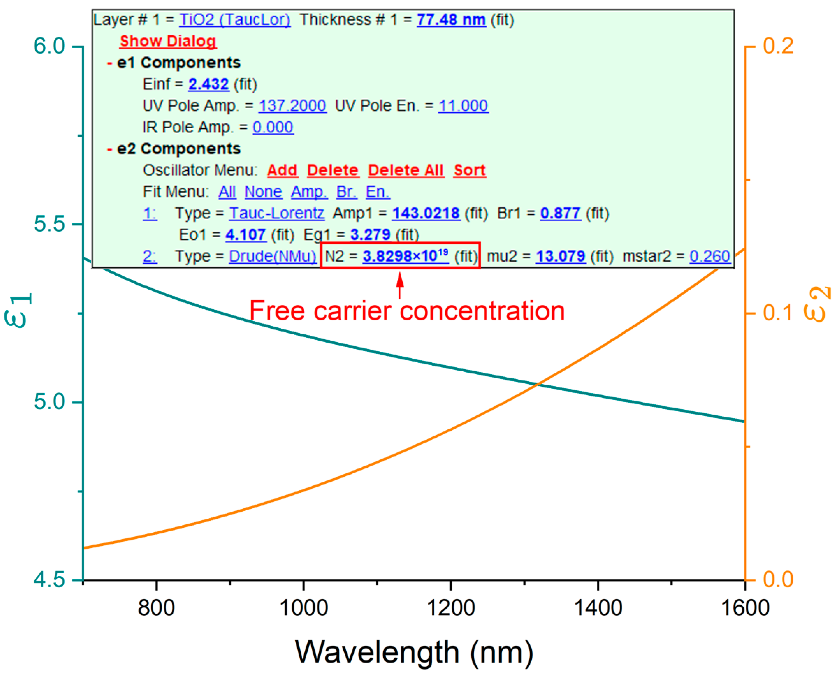
An example of the ellipsometry measurement for the fabricated TiOx film is shown in Figure 3. According to the obtained modeling results, the Ar/O2 flow ratio of 10 used during deposition yielded the desired free carrier concentration above 1019 1/cm3, demonstrating that this deposition condition is suitable for practical device fabrication. The dielectric permittivity of TiOx was calculated using the Drude model with parameters obtained from ellipsometry fitting shown in Figure 3: free carrier concentration N =   3.83 × 10¹⁹ 1/cm3, carrier mobility μ = 13.08 cm2∙V−1∙s−1, and effective electron mass m = 0.26 m 0 , where m 0 is the free electron mass. The developed model was then applied to predict variations in the dielectric permittivity caused by changes in free carrier concentration under an applied external voltage. Since the simulations were carried out in the NIR region, the dielectric permittivity of TiOx is also provided for the wavelength range from 700 nm to 1600 nm.
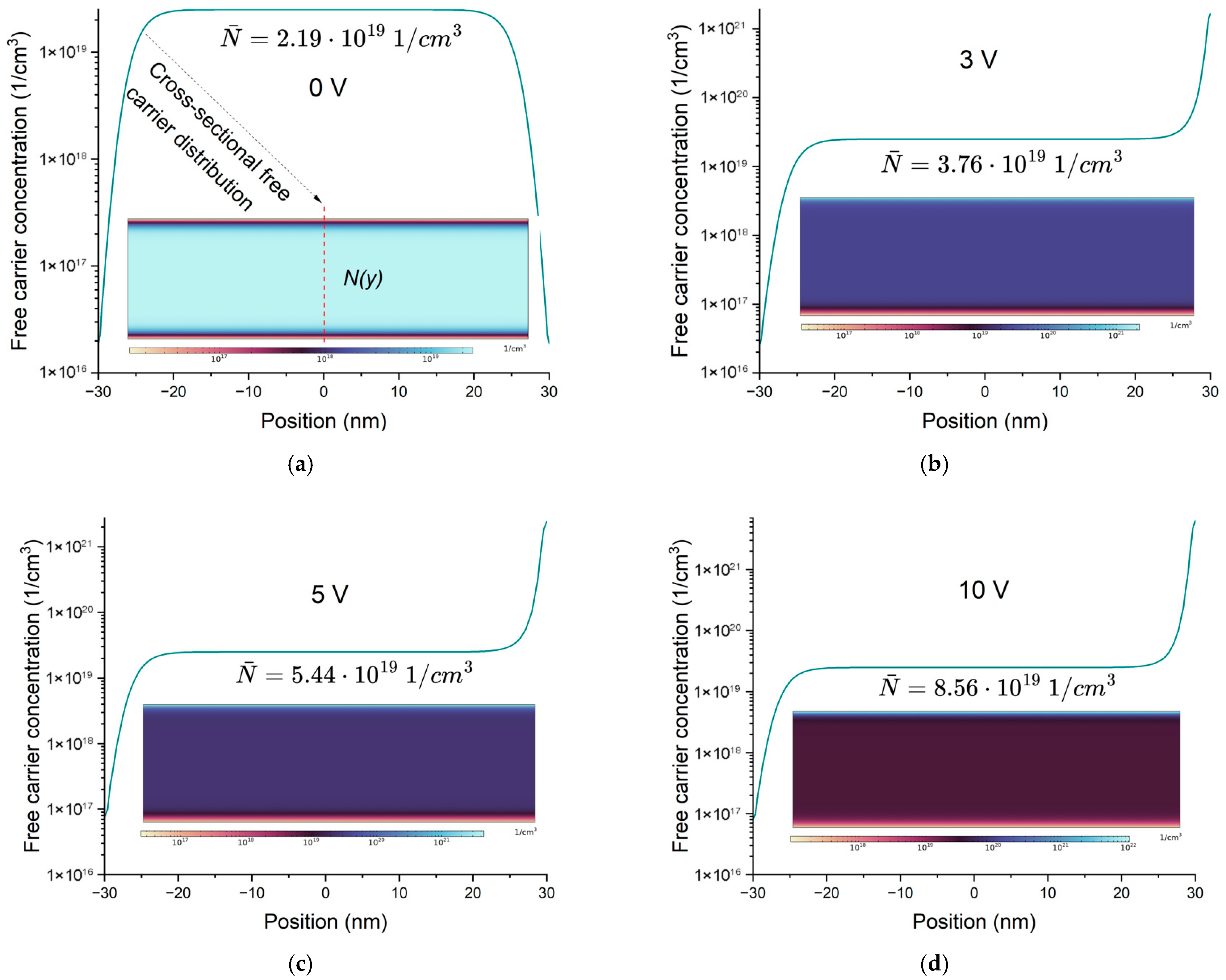
Figure 4 illustrates the distribution of free carriers in a 60 nm thick TiOx layer under an applied external electric field and the resulting changes in the LMR wavelength. Although the carrier distribution profiles appear visually similar due to the limited Debye length, the carrier density within the interfacial regions increases with applied voltage, as reflected in the color scale and quantified in the corresponding average carrier concentrations. The TiOx layer has a bulk free carrier concentration of 2.50 × 10¹⁹ 1/cm3. Even at 0 V, the carrier distribution is non-uniform due to the higher work function of ITO compared to the electron affinity of TiOx, which generates depletion regions at the interfaces [35]. When a voltage is applied to the top electrode, the carrier concentration near the interface increases significantly, but this modulation extends only about 5 nm into the TiOx layer because of the Debye length, leaving most of the layer unaffected. The carrier accumulation near the interfaces significantly influences the local optical properties of TiOx, as variations in carrier density within these narrow regions modify the permittivity and, in turn, affect the observed LMR behavior. Similar interfacial carrier redistribution and its impact on optical response have been reported in electrostatically tuned semiconducting oxide films [36,37,38]. Even with limited depth, the significant increase in carriers inside this region has a clear impact on the mean value across the film. As the applied voltage increases, the carrier modulation becomes more pronounced, resulting in stronger changes in the optical properties. The calculated average free carrier concentrations at 0 V, 3 V, 5 V, and 10 V are 2.19 × 10¹⁹ 1/cm3, 3.76 × 10¹⁹ 1/cm3, 5.44 × 10¹⁹ 1/cm3, and 8.56 × 10¹⁹ 1/cm3, respectively. These values were used to determine the corresponding changes in dielectric permittivity using the Drude model. Both the real and imaginary parts of the permittivity change under the applied field. The real part decreases while the imaginary part increases (see Figure 5a), and both components influence the LMR behavior. Figure 5b also shows that applying an external voltage shifts the LMR toward shorter wavelengths. This occurs because the dielectric permittivity of TiOx decreases with applied voltage, whereas LMR occurs at longer wavelengths when the refractive index is higher [7]. In addition, the resonance peak becomes shallower with increasing voltage. Although this might appear counterintuitive given the higher imaginary part of the TiOx permittivity, previous studies have shown that an increase in the extinction coefficient of lossy coatings can reduce resonance depth [7]. This behavior can be described through the Fabry–Perot interference model, where voltage-induced changes in the real and imaginary parts of the TiOx permittivity modify the internal phase conditions and reflection balance within the coating, reducing interference contrast and leading to a shallower resonance. The LMR shift exhibits a linear dependence on voltage, yielding a tuning efficiency of 4.0 nm/V for a structure comprising 20 nm thick ITO electrodes, 2 nm thick insulating Al2O3 layers, and a 60 nm thick TiOx layer. To achieve the first-order TM-polarized LMR at the target wavelength of 1310 nm, the cladding refractive index was adjusted to 1.527.
To investigate how the bulk free carrier concentration of TiOx thin film influences the LMR behavior, additional calculations were carried out for concentrations of 5.00 × 10¹⁹ 1/cm3 and 7.50 × 10¹⁹ 1/cm3, using the same device structure. Figure 6 shows that for a bulk concentration of 5.00 × 10¹⁹ 1/cm3, the average carrier concentration was 4.56 × 10¹⁹ 1/cm3 at 0 V and increased to 1.10 × 10²⁰ 1/cm3 at 10 V. For the case of 7.50 × 10¹⁹ 1/cm3, the corresponding values were 7.01 × 10¹⁹ 1/cm3 at 0 V and 1.35 × 10²⁰ 1/cm3 at 10 V. To obtain the first-order TM-polarized LMR at the target wavelength of 1310 nm, the cladding refractive index was set to 1.530 for the 5.00 × 10¹⁹ 1/cm3 concentration and 1.532 for the 7.50 × 10¹⁹ 1/cm3 concentration. The resulting tuning efficiencies were 4.0 nm/V and 3.9 nm/V, respectively, which are comparable to the value obtained for a bulk concentration of 2.50 × 10¹⁹ 1/cm3. These results indicate that tuning efficiency is only weakly dependent on the initial carrier concentration. This behavior can be explained by two compensating effects. On one hand, higher free carrier concentrations lead to stronger changes in the optical properties per unit variation in carrier density. On the other hand, the Debye length follows the relationship λ D 1 / N , which reduces the depth over which carriers are redistributed. The balance between these two factors results in nearly constant tuning efficiency across different starting concentrations. Consequently, further investigations were focused on the case of 2.50 × 10¹⁹ 1/cm3.
Figure 7 shows the effect of TiOx and ITO layer thickness on LMR behavior. For structures with thicker ITO electrodes, the overall LMR performance was degraded in terms of tuning efficiency, full width at half minimum (FWHM), and resonance depth. Tuning efficiency decreases because the TiOx layer represents a smaller portion of the stack, so its optical changes have less influence on the overall response. The broader FWHM originates from the refractive index of the cladding. As reported in the literature [7], FWHM is strongly dependent on the refractive index contrast between the waveguide core and the surrounding medium: when this contrast becomes small, the resonance broadens significantly. As noted earlier, the shallower resonance arises from the increase in the average extinction coefficient of the stack associated with thicker ITO layers. When comparing designs that differ only in TiOx thickness, with all other layers kept constant, the highest tuning efficiency was observed for the 60 nm TiOx coating. Although thinner TiOx represents a smaller portion of the total stack, it undergoes a larger relative change in free carrier concentration under applied bias. Because the Debye length limits carrier modulation to a region of about 5 nm near the interface, the proportion of this modulated region relative to the total film thickness is greater in thinner coatings, resulting in a stronger average effect. In terms of spectral characteristics, LMR peaks were narrower for thicker TiOx coatings, again due to the influence of the cladding refractive index. For thinner coatings, achieving a first-order TM-polarized LMR at the target wavelength of 1310 nm was not possible without increasing the cladding refractive index. However, increasing the cladding index reduces the refractive index contrast between the waveguide core and the external medium, which, as discussed above, inevitably broadens the resonance.
Because the individual performance metrics did not yield a clear indication of the optimal configuration, the figure of merit (FOM) was calculated for all tested designs (see Table 2) using the following equation:
FOM   =   tuning   efficiency   FWHM .
To highlight the relative performance of the proposed device, Table 3 summarizes key characteristics of representative EO tunable filter technologies reported in the literature, together with results obtained in this work.

4. Conclusions

This study demonstrates the potential of the LMR phenomenon for active integrated photonic devices such as tunable filters, thereby extending its use beyond conventional sensing applications. The developed tunable filter reached a tuning efficiency of 4.0 nm/V, which surpasses most EO tunable optical filters reported in the literature, including 0.34 nm/V in long-period grating filters [39], 0.016 nm/V in Bragg grating filters [40], 0.55 nm/V in photonic crystal-based filters [41], and 0.0019 nm/V in microring-based filters [42]. This result confirms that LMR can be effectively utilized not only for passive sensing but also for active wavelength control in photonic integrated circuits. Although the obtained tuning efficiency of 4.0 nm/V exceeds most reported EO tunable filters, it is associated with a relatively broad resonance and moderate extinction ratio, which are inherent characteristics of LMR-based devices. Such trade-offs can be mitigated by optimizing the refractive index contrast, TiOx stoichiometry, and electrode configuration to achieve improved balance between tuning efficiency and spectral selectivity.
The research also provided valuable insights into optimization strategies. The highest tuning efficiency was achieved when thinner electrodes were used, since this configuration allows the modulated TiOx layer to occupy a larger portion of the stack and exert a stronger influence on the optical response. Similarly, thinner modulated TiOx layers showed higher tuning efficiency because they undergo a larger relative change in free carrier concentration under applied bias. On the other hand, the absolute free carrier concentration was found to have little overall impact on tuning efficiency. This effect can be explained by two competing processes: higher carrier concentrations enhance changes in optical properties per unit variation, but at the same time the shorter Debye length reduces the depth of carrier redistribution. Another conclusion was that thicker TiOx layers lead to narrower FWHM. This can be attributed to the fact that in thicker coatings there is less dependence on a high refractive index of the cladding to shift the LMR to the desired wavelength, and a stronger refractive index contrast between core and cladding results in sharper resonances.
Although the present device exhibits a relatively broad resonance and a moderate extinction ratio, the achieved tuning efficiency demonstrates strong potential for practical implementation. Further optimization of the refractive index contrast, multilayer coating structure, and TiOx stoichiometry could lead to narrower and deeper resonances. The voltage-controlled LMR shift can also be utilized in single-wavelength sensing, where tuning the resonance to match a fixed optical source enables detection without the need for broadband illumination or spectrometers, offering a compact and cost-efficient platform for integrated photonic sensors. Beyond sensing, the proposed LMR-based device can also be applied in telecommunication and RF photonic systems, where voltage-controlled tuning of the resonance wavelength enables adjustment of signal transmission or attenuation. The achieved EO control allows reconfigurable operation without thermal tuning, while the use of polymer and oxide materials ensures compatibility with existing integrated photonic platforms.

Funding

This research was supported by European Regional Development Fund under project 1.1.1.9/LZP/1/24/117 “Electro-Optic Modulation Based on Lossy Mode Resonance”.

Data Availability Statement

The original contributions presented in this study are included in the article. Further inquiries can be directed to the corresponding author.

Acknowledgments

The author gratefully acknowledges the Institute of Solid State Physics and the European Regional Development Fund for providing the opportunity to publish this research.

Conflicts of Interest

The author declares no conflicts of interest.

References

  1. Wang, Q.; Zhao, W.M. A Comprehensive Review of Lossy Mode Resonance-Based Fiber Optic Sensors. Opt. Lasers Eng. 2018, 100, 47–60. [Google Scholar] [CrossRef]
  2. Sánchez, P.; Zamarreño, C.R.; Arregui, F.J.; Matías, I.R. LMR-Based Optical Fiber Refractometers for Oil Degradation Sensing Applications in Synthetic Lubricant Oils. J. Light. Technol. 2016, 34, 4537–4542. [Google Scholar] [CrossRef]
  3. Zamarreño, C.R.; Hernáez, M.; Del Villar, I.; Matías, I.R.; Arregui, F.J. Optical Fiber PH Sensor Based on Lossy-Mode Resonances by Means of Thin Polymeric Coatings. Sens. Actuators B Chem. 2011, 155, 290–297. [Google Scholar] [CrossRef]
  4. Zamarreño, C.R.; Hernaez, M.; Del Villar, I.; Matias, I.R.; Arregui, F.J. Tunable Humidity Sensor Based on ITO-Coated Optical Fiber. Sens. Actuators B Chem. 2010, 146, 414–417. [Google Scholar] [CrossRef]
  5. Elosúa, C.; Vidondo, I.; Arregui, F.J.; Bariain, C.; Luquin, A.; Laguna, M.; Matías, I.R. Lossy Mode Resonance Optical Fiber Sensor to Detect Organic Vapors. Sens. Actuators B Chem. 2013, 187, 65–71. [Google Scholar] [CrossRef]
  6. Letko, E.; Bundulis, A.; Vanags, E.; Mozolevskis, G. Lossy Mode Resonance in Photonic Integrated Circuits. Opt. Lasers Eng. 2024, 181, 108387. [Google Scholar] [CrossRef]
  7. Zhao, W.M.; Wang, Q. Analytical Solutions to Fundamental Questions for Lossy Mode Resonance. Laser Photon Rev. 2023, 17, 2200554. [Google Scholar] [CrossRef]
  8. Arregui, F.J.; Del Villar, I.; Corres, J.M.; Goicoechea, J.; Carlos, R.; Elosua, C.; Hernaez, M.; Rivero, P.J.; Socorro, A.B.; Sanchez, P.; et al. Fiber-Optic Lossy Mode Resonance Sensors. Procedia Eng. 2014, 87, 3–8. [Google Scholar] [CrossRef]
  9. Refractometer, F.; Sudas, D.P.; Zakharov, L.Y.; Jitov, V.A.; Golant, K.M. Silicon Oxynitride Thin Film Coating to Lossy Mode Resonance. Sensors 2022, 22, 3665. [Google Scholar] [CrossRef] [PubMed]
  10. Vos, M.; Grande, P.L. Simple Model Dielectric Functions for Insulators. J. Phys. Chem. Solids 2017, 104, 192–197. [Google Scholar] [CrossRef]
  11. Śmietana, M.; Burnat, D.; Curda, P.; Janaszek, B.; Kieliszczyk, M.; Sezemsky, P.; Koba, M.; Stranak, V.; Szczepański, P. Electro-Optically Modulated Lossy-Mode Resonance—A New Approach for Label-Free Sensing. ACS Photonics 2024, 11, 2061–2069. [Google Scholar] [CrossRef]
  12. Letko, E.; Bundulis, A.; Mozolevskis, G. Theoretical Development of Polymer-Based Integrated Lossy-Mode Resonance Sensor for Photonic Integrated Circuits. Photonics 2022, 9, 764. [Google Scholar] [CrossRef]
  13. Zuo, H.; Yu, S.; Gu, T.; Hu, J. Low Loss, Flexible Single-Mode Polymer Photonics. Opt. Express 2019, 27, 11152. [Google Scholar] [CrossRef]
  14. Girschikofsky, M.; Rosenberger, M.; Förthner, M.; Rommel, M.; Frey, L.; Hellmann, R. Waveguide Bragg Gratings in Ormocer®s for Temperature Sensing. Sensors 2017, 17, 2459. [Google Scholar] [CrossRef]
  15. Madani, A.; Azarinia, H.; Latifi, H. Design and Fabrication of a Polymer Micro Ring Resonator with Novel Optical Material at Add/Drop Geometry Using Laser Beam Direct Write Lithography Technique. Optik 2013, 124, 1746–1748. [Google Scholar] [CrossRef]
  16. Liang, Y.; Zhao, M.; Wu, Z.; Morthier, G. Bimodal Waveguide Interferometer RI Sensor Fabricated on Low-Cost Polymer Platform. IEEE Photonics J. 2019, 11, 6801108. [Google Scholar] [CrossRef]
  17. Julian, M.N.; Williams, C.; Borg, S.; Bartram, S.; Kim, H.J. Reversible Optical Tuning of GeSbTe Phase-Change Metasurface Spectral Filters for Mid-Wave Infrared Imaging. Optica 2020, 7, 746. [Google Scholar] [CrossRef]
  18. Gökbulut, B. A Hybrid Photonic-Plasmonic Resonator Based on a Partially Encapsulated 1D Photonic Crystal Waveguide and a Plasmonic Nanoparticle. Heliyon 2022, 8, e12346. [Google Scholar] [CrossRef]
  19. Ciminelli, C.; Dell’Olio, F.; Brunetti, G.; Conteduca, D.; Armenise, M.N. New Microwave Photonic Filter Based on a Ring Resonator Including a Photonic Crystal Structure. In Proceedings of the 19th International Conference on Transparent Optical Networks, Girona, Spain, 2–6 July 2017; pp. 3–6. [Google Scholar] [CrossRef]
  20. Cheng, W.; Lin, D.; Wang, P.; Shi, S.; Lu, M.; Wang, J.; Guo, C.; Chen, Y.; Cang, Z.; Tian, Z.; et al. Tunable Bandpass Microwave Photonic Filter with Largely Reconfigurable Bandwidth and Steep Shape Factor Based on Cascaded Silicon Nitride Micro-Ring Resonators. Opt. Express 2023, 31, 25648. [Google Scholar] [CrossRef] [PubMed]
  21. Ren, Y.; Perron, D.; Aurangozeb, F.; Jiang, Z.; Hossain, M.; Van, V. Silicon Photonic Vernier Cascaded Microring Filter for Broadband Tunability. IEEE Photonics Technol. Lett. 2019, 31, 1503–1506. [Google Scholar] [CrossRef]
  22. Khattou, S.; Rezzouk, Y.; Amrani, M.; El Ghafiani, M.; El Boudouti, E.H.; Talbi, A.; Djafari-Rouhani, B. Friedrich-Wintgen Bound States in the Continuum in a Photonic and Plasmonic T -Shaped Cavity: Application to Filtering and Sensing. Phys. Rev. Appl. 2023, 20, 1. [Google Scholar] [CrossRef]
  23. Wei, B.; Chen, H.; Hua, W.; Chen, M.; Ding, X.; Li, C. Formation Mechanism and Photoelectric Properties of Al2O3 Film Based on Atomic Layer Deposition. Appl. Surf. Sci. 2022, 572, 151419. [Google Scholar] [CrossRef]
  24. Niedziałkowski, P.; Białobrzeska, W.; Burnat, D.; Sezemsky, P.; Stranak, V.; Wulff, H.; Ossowski, T.; Bogdanowicz, R.; Koba, M.; Śmietana, M. Electrochemical Performance of Indium-Tin-Oxide-Coated Lossy-Mode Resonance Optical Fiber Sensor. Sens. Actuators B Chem. 2019, 301, 127043. [Google Scholar] [CrossRef]
  25. Letko, E.; Bundulis, A.; Mozolevskis, G. Lossy Mode Resonance Sensors Based on Planar Waveguides: Theoretical and Experimental Comparison. IEEE Photonics J. 2024, 16, 6800107. [Google Scholar] [CrossRef]
  26. Walker, J.M.; Akbar, S.A.; Morris, P.A. Synergistic Effects in Gas Sensing Semiconducting Oxide Nano-Heterostructures: A Review. Sens. Actuators B Chem. 2019, 286, 624–640. [Google Scholar] [CrossRef]
  27. Von Blanckenhagen, B.; Tonova, D.; Ullmann, J. Application of the Tauc-Lorentz Formulation to the Interband Absorption of Optical Coating Materials. Appl. Opt. 2002, 41, 3137–3141. [Google Scholar] [CrossRef]
  28. Tan, W.C.; Koughia, K.; Singh, J.; Kasap, S.O. Fundamental Optical Properties of Materials I. In Optical Properties of Condensed Matter and Applications; Wiley: Hoboken, NJ, USA, 2006; pp. 1–25. [Google Scholar] [CrossRef]
  29. Fuentes, O.; Del Villar, I.; Corres, J.M.; Matias, I.R. Lossy Mode Resonance Sensors Based on Lateral Light Incidence in Nanocoated Planar Waveguides. Sci. Rep. 2019, 9, 1–10. [Google Scholar] [CrossRef] [PubMed]
  30. Justice, P.; Marshman, E.; Singh, C. Student Understanding of Fermi Energy, the Fermi-Dirac Distribution and Total Electronic Energy of a Free Electron Gas. Eur. J. Phys. 2020, 41, 015704. [Google Scholar] [CrossRef]
  31. Bulyarskiy, S.V.; Koiva, D.A.; Belov, V.S.; Zenova, E.V.; Rudakov, G.A.; Gusarov, G.G. Titanium Oxide Thin Films Stoichiometric Composition Dependence on the Oxygen Flow at Magnetron Sputtering. Thin Solid. Film. 2022, 741, 138991. [Google Scholar] [CrossRef]
  32. Tekin, S.B.; Almalki, S.; Finch, H.; Vezzoli, A.; O’Brien, L.; Dhanak, V.R.; Hall, S.; Mitrovic, I.Z. Electron Affinity of Metal Oxide Thin Films of TiO2, ZnO, and NiO and Their Applicability in 28.3 THz Rectenna Devices. J. Appl. Phys. 2023, 134, 084503. [Google Scholar] [CrossRef]
  33. Choi, J.H.; Kim, J.W.; Oh, T.S. Dielectric Properties and Leakage Current Characteristics of Al2O3 Thin Films with Thickness Variation. Mater. Res. Soc. Symp.-Proc. 2001, 666, 1–6. [Google Scholar] [CrossRef]
  34. Nehate, S.D.; Prakash, A.; Mani, P.D.; Sundaram, K.B. Work Function Extraction of Indium Tin Oxide Films from MOSFET Devices. ECS J. Solid. State Sci. Technol. 2018, 7, 87–90. [Google Scholar] [CrossRef]
  35. Zhang, Z.; Yates, J.T. Band Bending in Semiconductors: Chemical and Physical Consequences at Surfaces and Interfaces. Chem. Rev. 2012, 112, 5520–5551. [Google Scholar] [CrossRef]
  36. Xu, Y.; Sun, H. Electronic Transport and Interface Properties of FeOCl-Type Monolayer SnNCl for Flexible Nanodevices. Surf. Interfaces 2025, 65, 106524. [Google Scholar] [CrossRef]
  37. Liu, X.; Kang, J.H.; Yuan, H.; Park, J.; Kim, S.J.; Cui, Y.; Hwang, H.Y.; Brongersma, M.L. Electrical Tuning of a Quantum Plasmonic Resonance. Nat. Nanotechnol. 2017, 12, 866–870. [Google Scholar] [CrossRef]
  38. Wang, H.; Zhang, J.; Zhao, H. Surface Plasmon Polariton Excitation by Electrostatic Modulation and Phase Grating in Indium-Tin-Oxide Coated Lithium Niobate Slabs. J. Appl. Phys. 2015, 118, 063102. [Google Scholar] [CrossRef]
  39. Li, J.; Yao, H.; Deng, J.; Hu, Z.; Zhao, Z.; Ma, X.; Chen, K. Electro-Optic Tunable Optical Filter Based on Long-Period Waveguide Grating in Lithium Niobate on Insulator with Absorption Ribbons. Opt. Express 2023, 31, 30658. [Google Scholar] [CrossRef] [PubMed]
  40. Li, Q.; Zhu, H.; Hu, Y.; Yang, F.; Zang, Z.; Ou, J.; Han, H.; Ruan, S.; Han, P.; Xiang, B. Electro-Optic Tunable Bragg Grating Filters on Hybrid Silicon and Lithium Niobate Thin Films. Opt. Express 2024, 32, 46335. [Google Scholar] [CrossRef]
  41. Fu, Y.; Zhang, J.; Hu, X.; Gong, Q. Electro-Optic Tunable Multi-Channel Filter in Two-Dimensional Ferroelectric Photonic Crystals. J. Opt. 2010, 12, 075202. [Google Scholar] [CrossRef]
  42. Yu, J.; Ruan, Z.; Xue, Y.; Wang, H.; Gan, R.; Gao, T.; Guo, C.; Chen, K.; Ou, X.; Liu, L. Tunable and Stable Micro-Ring Resonator Based on Thin-Film Lithium Tantalate. APL Photonics 2024, 9, 036115. [Google Scholar] [CrossRef]
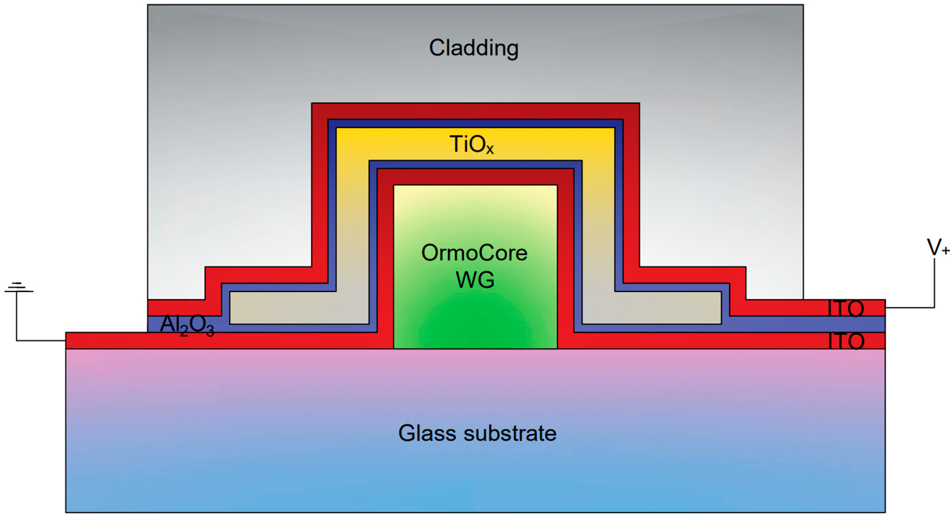
Figure 1. Schematic cross-sectional design of the EO tunable filter based on LMR.
Photonics 12 01086 g001
Figure 2. Free carrier distribution as a function of y coordinate in 60 nm thick TiOx at 0 V bias.
Photonics 12 01086 g002
Figure 3. Real and imaginary parts of the dielectric permittivity for the sputtered TiOx thin film, obtained from ellipsometry modeling together with the corresponding free carrier concentration exceeding 1019 1/cm3.
Photonics 12 01086 g003
Figure 4. Free carrier distribution under applied external bias in 60 nm thick TiOx with bulk free carrier concentration of 2.50 × 10¹⁹ 1/cm3: (a) 0 V, (b) 3 V, (c) 5 V, and (d) 10 V.
Photonics 12 01086 g004
Figure 5. Changes in optical properties under applied external bias in 60 nm thick TiOx with bulk free concentration of 2.50 × 10¹⁹ 1/cm3: (a) dielectric permittivity, and (b) LMR shift.
Photonics 12 01086 g005
Figure 6. LMR shift under applied external bias in 60 nm thick TiOx with bulk free concentrations of 5.00 × 10¹⁹ 1/cm3 and 7.50 × 10¹⁹ 1/cm3.
Photonics 12 01086 g006
Figure 7. LMR response under applied external bias in various device designs: (a) 30 nm ITO electrodes and 40 nm TiOx, (b) 20 nm ITO electrodes and 60 nm TiOx, (c) 20 nm ITO electrodes and 100 nm TiOx, (d) 20 nm ITO electrodes and 150 nm TiOx.
Photonics 12 01086 g007
Table 1. Properties of materials used in the simulation of TiOx free carrier behavior.
MaterialPhysical ParameterValueReference
TiOx Relative   permittivity   ε 40[31]
Band   gap   E g 3.3 V[32]
Electron   affinity   χ 3.9 V[32]
Al2O3 Relative   permittivity   ε 9[33]
Thickness2 nm
ITO Work   function   Φ 4.6 V[34]
Table 2. Performance metrics for various configurations.
ConfigurationTuning Efficiency, nm/VFWHM, nmFOM, V−1
2 nm Al2O3, 30 nm ITO, 40 nm TiOx3.21440.022
2 nm Al2O3, 20 nm ITO, 60 nm TiOx4.01300.031
2 nm Al2O3, 20 nm ITO, 100 nm TiOx2.0980.020
2 nm Al2O3, 20 nm ITO, 150 nm TiOx1.6710.023
Table 3. Comparison of EO tunable filter technologies.
TechnologyTuning Efficiency, nm/VFWHM, nmFOM, V−1
Long-period grating filter [39]0.345.00.068
Bragg grating filter [40]0.0160.300.053
Photonic crystal-based filter [41]0.55240.023
Microring-based filter [42]0.00190.00500.38
LMR-based filter4.01300.031
Disclaimer/Publisher’s Note: The statements, opinions and data contained in all publications are solely those of the individual author(s) and contributor(s) and not of MDPI and/or the editor(s). MDPI and/or the editor(s) disclaim responsibility for any injury to people or property resulting from any ideas, methods, instructions or products referred to in the content.