1. Introduction
This article presents the development and characterization of X-ray payload created as part of the Space Radiation Capabilities, Technologies, and Platforms for Small Spacecraft (SR-CTP) initiative of the European Space Agency (ESA). The project’s main goal was to design a CubeSat demonstrator that achieved Technology Readiness Level 7 (TRL 7). This included X-ray optics, detectors, read-out electronics, and basic software.
Lobster Eye (LE) X-ray optics have recently gained traction in wide-field astrophysical and geospace missions due to their ability to achieve large field of view (FOV) imaging with compact, lightweight designs. This optical approach is particularly well suited for CubeSat platforms, where volume, mass, and power are limited. CubeSat is a type of miniaturized satellite composed of standardized cubic units (called “U”) measuring 10 × 10 × 10 cm. CubeSats can consist of one or more units (e.g., 1U, 3U, 6U, or 12U) and are designed to be low-cost and lightweight. CubeSats are also designed to be suitable for launching as secondary payloads. Originally intended for educational purposes, CubeSats are now widely used for scientific, commercial, and even interplanetary missions.
This paper focuses on the detailed characterization of the LE X-ray optics before integration into the demonstrator. Key optical parameters, such as field of view (FOV), angular resolution, focal length, and off-axis imaging behavior, were experimentally evaluated in a dedicated vacuum facility. The testing campaign was conducted in Prague in collaboration with VZLU Aerospace, the Czech Republic.
2. Motivation
In recent years, several space agencies have LE X-ray optics, confirming the growing interest in wide-field X-ray imaging for astrophysical applications.
NASA deployed the first LE X-ray imager onboard a Black Brant IX sounding rocket in 2012 as part of the STORM/DXL experiment [
1], using a newly developed slumped micropore configuration.
The ESA–JAXA BepiColombo mission, launched in October 2018, is a dual-spacecraft mission to study Mercury’s interior, surface, exosphere, and magnetosphere. It consists of the ESA Mercury Planetary Orbiter and the Mercury Imaging X-ray Spectrometer (MIXS) instrument. This collimated X-ray spectrometer features a micropore collimator design derived from LE geometry [
2,
3]. This instrument is designed to study the fluorescence of X-rays from the surface of Mercury induced by solar X-rays.
In July 2022, the Chinese Academy of Sciences launched the Lobster Eye Imager for Astronomy (LEIA) as a technology demonstration for wide-field X-ray imaging using micropore optics (MPO) [
4]. LEIA successfully validated the optical and detector concepts in orbit, paving the way for the Einstein Probe (EP) mission.
Launched in January 2024, the Einstein Probe (EP) is a dedicated small satellite mission designed to detect and monitor soft X-ray transients. Its primary instrument, the Wide Field X-ray Telescope (WXT), consists of twelve MPO-based LE modules that cover a combined field of view of 3600 square deg. EP combines wide sky coverage with a narrow-field follow-up telescope and targets phenomena such as tidal disruption events, gamma-ray bursts, and gravitational wave counterparts [
5,
6].
The upcoming SMILE mission (Solar wind Magnetosphere Ionosphere Link Explorer), jointly developed by ESA and CAS, is scheduled to launch in 2025. It extends the use of LE optics beyond astrophysics. Its Soft X-ray Imager (SXI) uses MPO-based Angel geometry to observe solar wind charge exchange (SWCX) interactions in the Earth’s magnetosphere, demonstrating the broader applicability of this technology for geospace science [
7,
8].
All of these missions employ LE optics based on micropore optics (MPO) using Angel geometry [
9], in which square-shaped channels are arranged to provide two-dimensional focusing. This approach has proven successful, but it presents certain manufacturing challenges.
As an alternative to the Angel-type configuration, our work adopts the Schmidt geometry [
10] implemented using Multi-Foil Optics (MFO). Instead of microchannels, this design utilizes stacked flat reflective foils arranged in two orthogonal modules to achieve two-dimensional focusing. This concept offers several practical advantages (such as higher gain and larger spectral coverage), particularly for CubeSat platforms, including simpler manufacturing, modular design, and the flexibility to apply reflective coatings using different high-Z materials (e.g., Au, Ir, Ru).
3. Lobster Eye Optic
A Multi-Foil Optics type X-ray Lobster Eye (LE) optic optimized for a 4U CubeSat has been designed, manufactured, and tested. The MFO refers to an approach in which a large number of thin reflective foils are assembled into a complete optical module. These foils are typically made from smooth float glass substrates with a surface microroughness of 1–2 nm root mean square (RMS). This is essential for minimizing X-ray scattering and preserving optical performance. This optical arrangement allows for effective two-dimensional focusing while maintaining a compact, lightweight design. This makes it ideal for use on CubeSat platforms.
The design is based on the Schmidt geometry, where flat reflecting foils are arranged in a uniform radial pattern along the perimeter of a spherical surface with radius
R. X-ray radiation reflected from foils on a curved surface of radius
R is focused at one point on the focal surface
F at a focal distance of
(
Figure 1).
The optical design relies on a single reflection per submodule. The critical angle of reflection is selected to ensure approximately 75% reflectivity at the typical operating energy of 2 keV. The theoretical efficiency of a full 2D MFO system, which includes two reflections, is estimated to be around 55%. This loss is due to rays that pass through the system without reflection or are absorbed within the submodules.
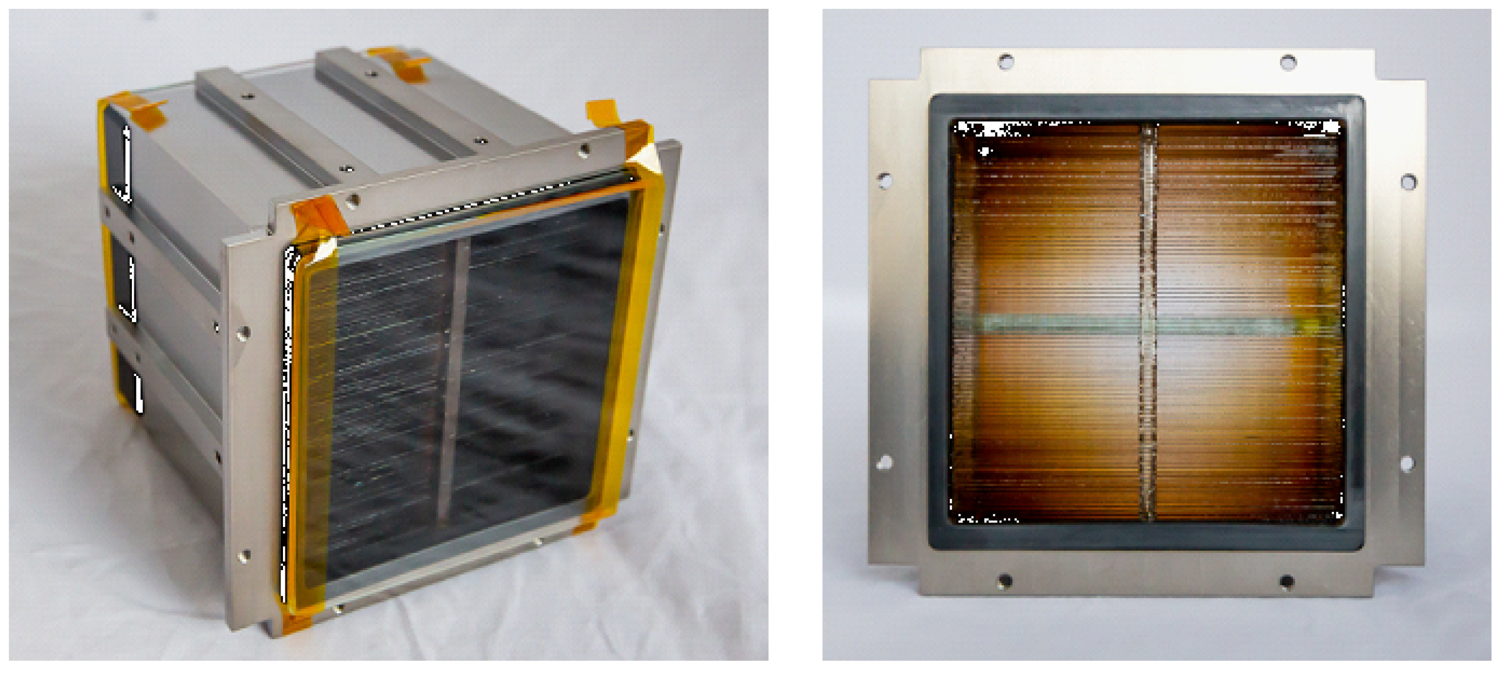
The 2D LE optic developed for the SR-CTP demonstrator is shown in
Figure 2. Each submodule consists of flat, gold-coated glass foils with dimensions of 25 × 75 × 0.145 mm. The optical aperture of each submodule measures 69 × 69 mm.
The optical parameters have been optimized to meet CubeSat requirements. In pointing mode, the instrument is stabilized to observe a field of view (FOV) of 5.8 × 5.4 deg, with a short focal length of approximately 400 mm and an angular resolution () better than 10 arcmin @ 2 keV. The effective area () is approximately 11.5 cm2 at an energy of 2–3 keV.
The 2D LE optic is designed to operate within an energy range of 0.5 keV to 10 keV. Beyond 10 keV, it functions effectively as a collimator. The main parameters of the 2D LE optic for the SR-CTP 4U CubeSat demonstrator are summarized in
Table 1.
During co-focusing to form the 2D optics, the two 1D submodules are mounted in series along the optical axis. Submodule A is located upstream of submodule B. In order to position their linear focus on the same detector plane, the one submodule is intentionally specified with a longer nominal focal length than the other. The required offset is greater than
where
and
are the nominal focal lengths of the submodules and
is their minimal axial spacing (approximately the submodule width). In practice, to accommodate assembly tolerances we use a safety margin and choose
, which ensures co-focus without additional optics.
4. Detector System for Demonstrator
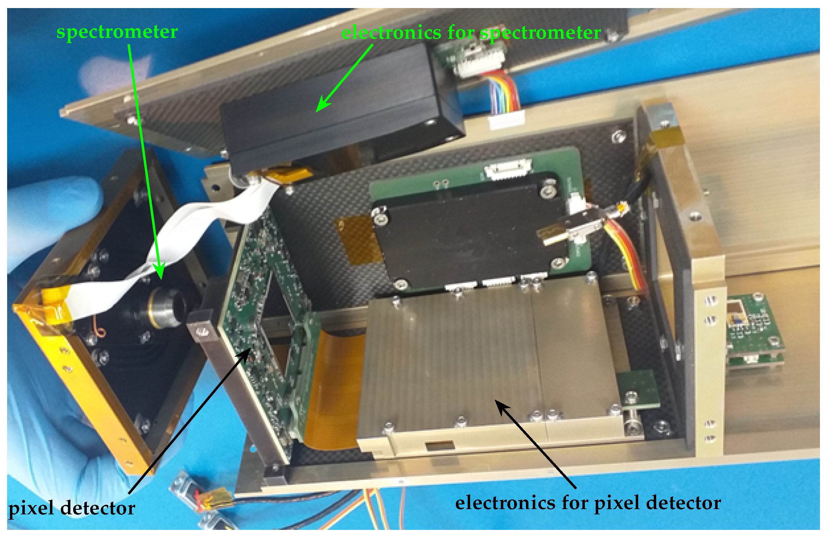
The optical payload developed for the 4U CubeSat demonstrator incorporates a novel detector system (SRC-TP detector in
Figure 3) that combines imaging capabilities with spectroscopic performance. This system comprises two main components, namely a pixel detector and a spectrometer.
The Quad platform is a custom detector optimized for large-area (28 × 28 mm) X-ray imaging applications, such as the focal plane of the 2D LE optic demonstrator. The total sensitive area is 7.8 cm2. Each pixel detector covers an area of 14.08 × 14.08 mm (256 × 256 pixels), where each pixel measures 55 µm × 55 µm and is connected to its individual readout channel. The Timepix3 sensor is based on 100 µm thick silicon and provides a detection range of 4 to 60 keV, with an energy resolution of approximately 15% of the incident energy (e.g., 0.9 keV at 6 keV).
The Silicon Drift Detector (SDD) H7LE represents state-of-the-art X-ray sensor technology, operating in an energy range of 0.5 keV to 30 keV. With an effective detection area of 7 mm2, it is well suited for low-energy applications. It offers excellent energy resolution, better than 70 eV at the carbon K line (277 eV), and down to 123 eV at the manganese K line (5.9 keV). The detector employs advanced thermal management, maintaining chip temperatures as low as −60 °C, and stable performance at heat sink temperatures up to +65 °C.
5. Ray Tracing
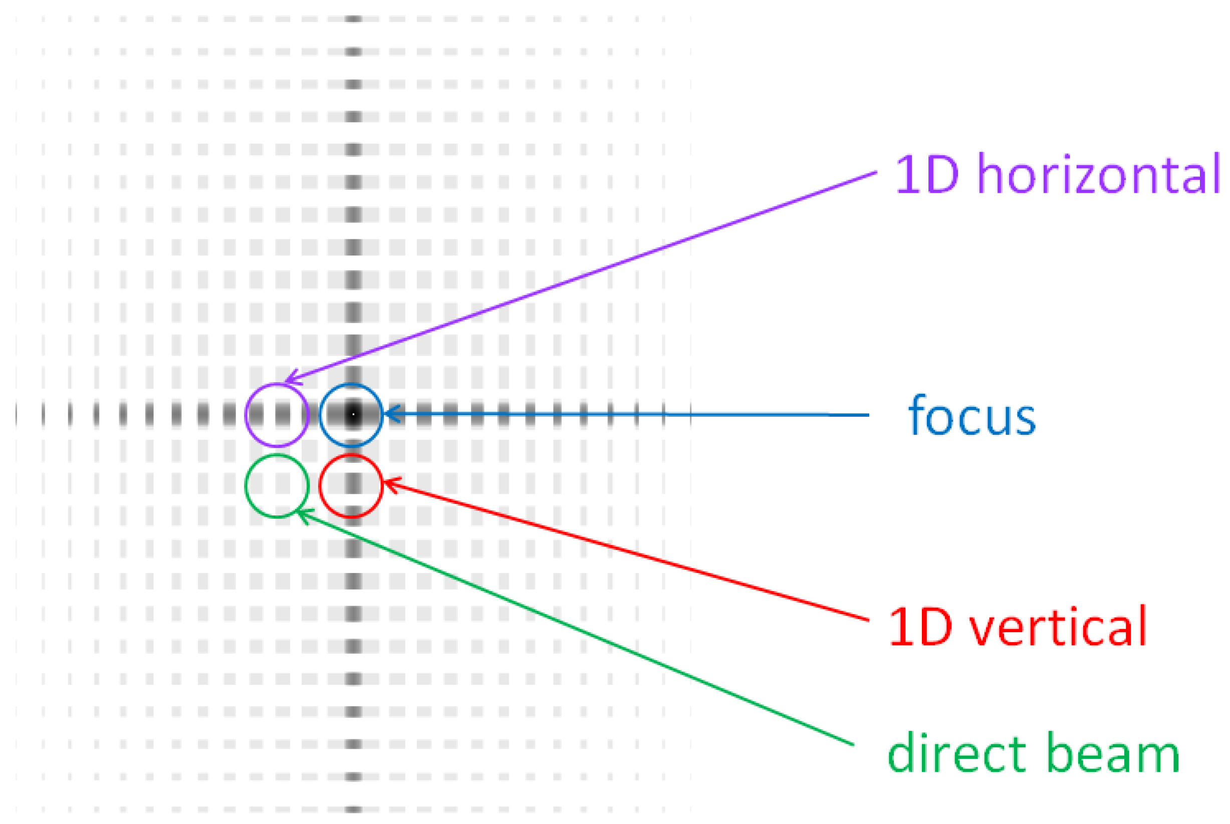
The design of LE X-ray optics for the CubeSat demonstrator is based on the LE Schmidt X-ray arrangement. LE optics can be configured as either a one-dimensional (1D) system or a two-dimensional (2D) system, the latter composed of two orthogonal 1D modules. This configuration is referred to as a Schmidt design, in which the two submodules are arranged perpendicularly and share a common focal plane (
Figure 5).
The reflectivity of the optical system depends on several key parameters, including the material properties, surface roughness, and waviness of the reflective foils. In the design and construction of X-ray optics, all materials used must exhibit a real part of the refractive index smaller than one, which is a necessary condition for total external reflection of X-rays. The most widely used reflective materials for X-ray optics include gold (Au), iridium (Ir), ruthenium (Ru), and nickel (Ni) (
http://henke.lbl.gov/optical_constants/, accessed on 30 October 2025).
This LE optic operates on the basis of the total external reflection of incoming X-ray photons. The design of LE optics follows the straightforward principle that the critical angle equals the limit angle ( = ) for a given photon energy, the reflective material, and surface roughness. The is the angle between the incoming beam and the reflecting foil surface. This relationship ensures that all foils contributing to the system focus X-rays at the focal point, satisfying the condition for total reflection.
The LE optics for the CubeSat demonstrator are designed for the 100 eV to 30 keV energy range. Above 10 keV, the LE optics act as a collimator, i.e., the X-rays are not reflected from the foil surface at a small angle, but the direct beam is incident on the detector (
Figure 5). In pointed mode, the device is oriented and stabilized in space to observe a 5.8 deg × 5.4 deg area of the sky with a resolution better than 10 arcmin .
The ray tracing was performed using Rigaku LeSim in-house software [
11]. LeSim allows for the ray tracing of 1D and/or 2D MFO optics (with focal length
L, aperture
A, mirror spacing
s, etc.) at different energies and on various reflective surfaces (material and microroughness RMS). In this calculation, each foil is considered an ideal, flat, reflective surface with a roughness of 1 nm and no macroscopic deformation.
The detector size in the basic simulation was chosen to be 512 pixel × 512 pixel (28.16 × 28.16 mm) with a pixel size of 55 µm. The source is expected to be an ideal monochromatic parallel beam with a divergence of 0 deg.
All key parameters of the X-ray LE optics (FWHM, gain
G, effective area
, and angular resolution
) were studied for different energies
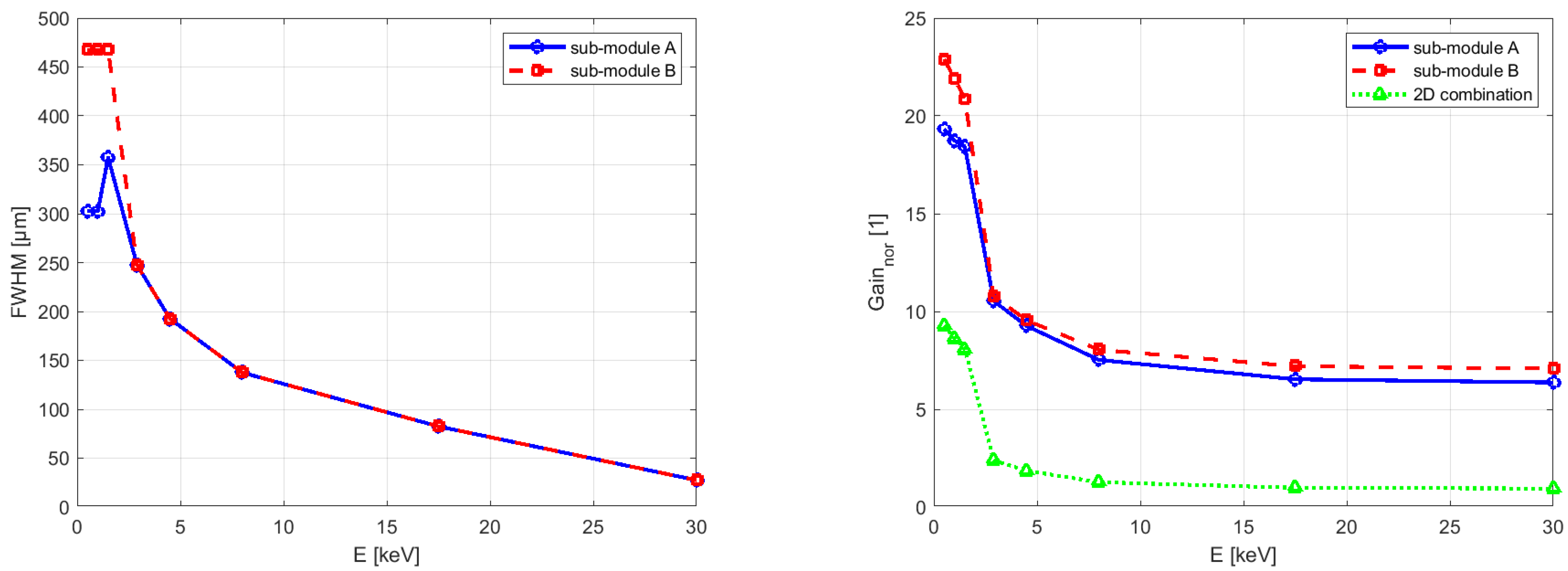
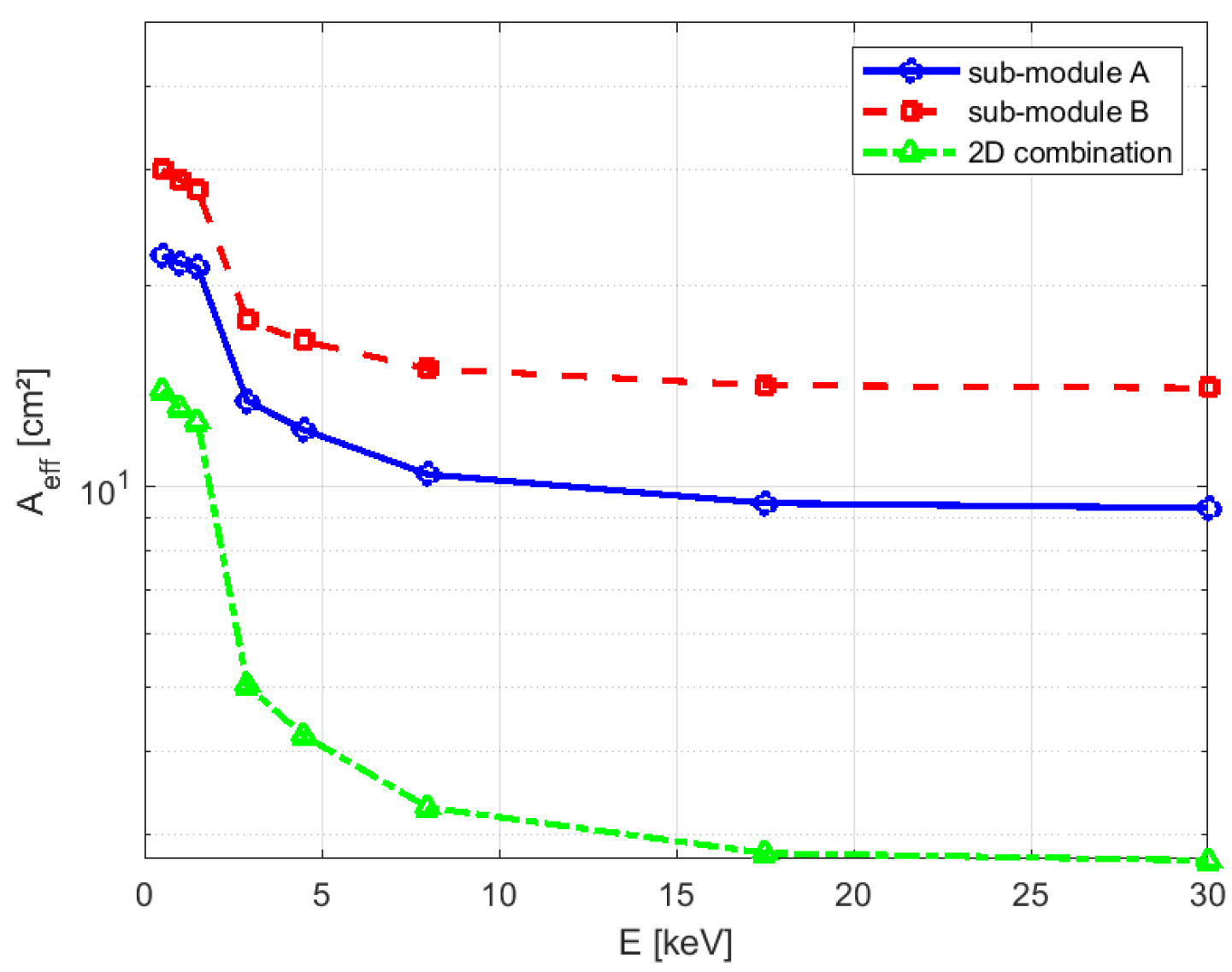
E (0.45 keV, 0.93 keV, 1.45 keV, 2.9 keV, 4.5 keV, 8.0 keV, 17.5 keV, and 30 keV). The results of these simulations are summarized in the following plots—
Figure 6 and
Figure 7.
Ray-tracing simulations confirm that LE optics work efficiently up to about 10 keV. At higher photon energies, the reflectivity of the surface decreases significantly, and the optics behave more like a collimator, through which the X-rays pass without reflection.
The results also show differences in performance between submodule A and submodule B. These differences are mainly due to the different foil spacing in each submodule, which affects optical parameters such as effective area and angular resolution. As a result, the combined 2D focus formed by the two orthogonal modules is slightly elliptical rather than circular.
6. The X-Ray Testing
X-ray vacuum testing was conducted to verify the key optical parameters of the LE system. Measurements were taken separately for each one-dimensional (1D) submodule, and then for the full two-dimensional (2D) optical assembly.
Two detectors were used during testing, a Rigaku CMOS camera and a Quad detector system with electrical ground support equipment (EGSE) electronics. Later, the complete 2D optical assembly was tested within the demonstrator using the integrated SRCTP detector system (Quad and spectrometer).
The Rigaku detector is optimized for soft X-ray detection. It has a field of view of 2473 × 3297 pixels, which corresponds to a physical area of 17.96 × 13.52 mm. With a pixel size of 5.4 µm, the system provides a high spatial resolution, allowing a detailed characterization of the focal point image and the angular response.
The Rigaku detector operated within an energy range of 1–5 keV, which covered all the photon energies used in the experiment. This ensured efficient signal acquisition across the relevant spectral range.
An X-ray tube with a multi-target anode assembly served as the source (
Table 2). The available target materials included nickel phosphor (NiP, operated at 0.85 keV, 2.0 keV, and 7.5 keV), silver (Ag, 3.0 keV), and titanium (Ti, 4.5 keV). This enabled energy-tunable illumination across a wide spectral range.
The operation of the tube at an accelerating voltage of 15 kV and a tube current of 20 A provided a stable, sufficient flux to image and characterize the optical system.
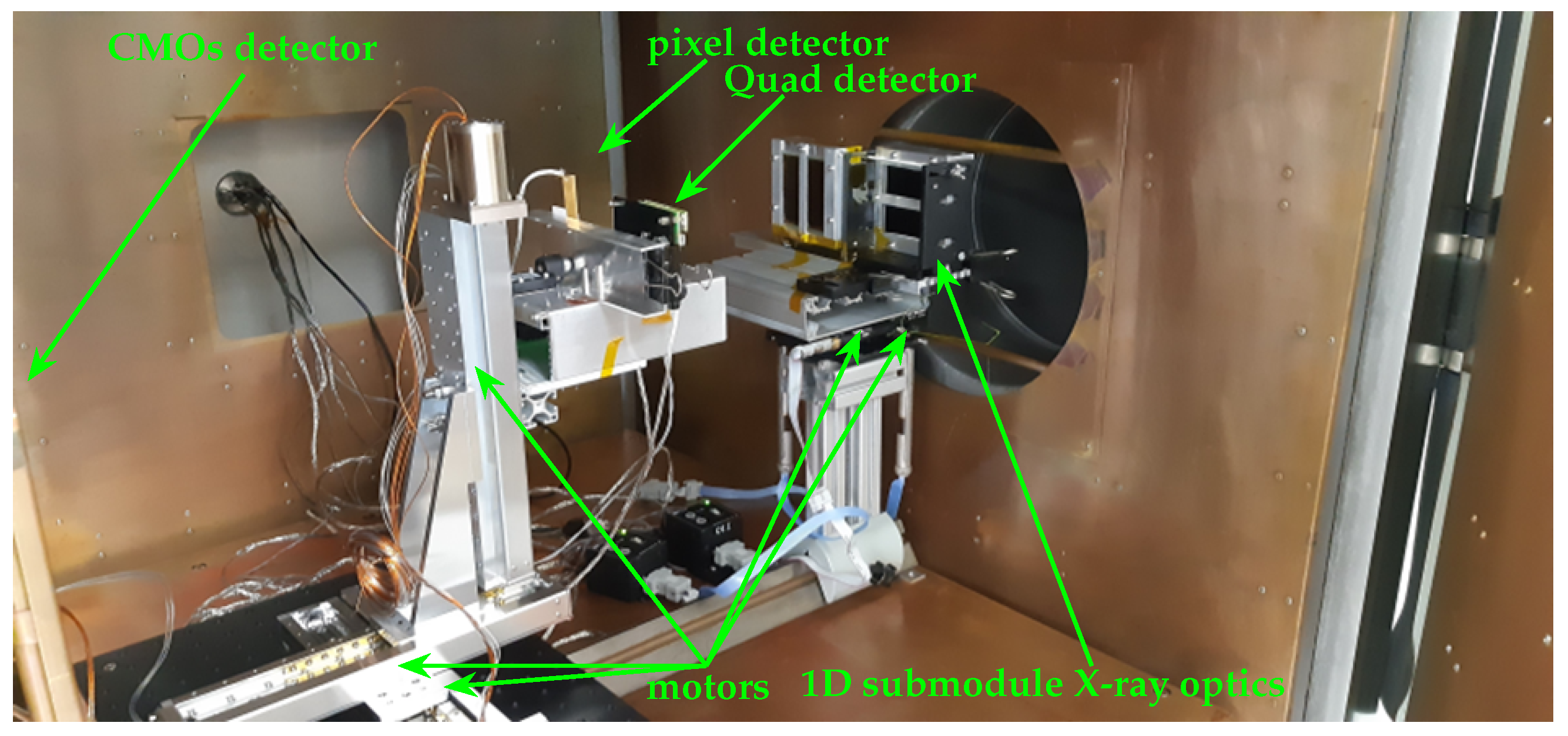
Measurements were taken in the vacuum chamber with the source and detector 10 m apart. The source and detector positions were fixed while the optics were mounted on motorized stages that allowed translation and rotation along the X, Y, and Z axes (
Figure 8). During the characterization of the optical system, the key parameters evaluated included focal length, angular resolution, field of view, effective area, and off-axis imaging performance. We systematically analyzed these parameters to evaluate the focusing quality and imaging capabilities of the 2D X-ray LE optics across various target materials and photon energies.
6.1. Focal Length
X-ray vacuum testing was conducted to verify the key optical parameters of the LE system. Measurements were taken separately for each one-dimensional (1D) submodule and then for the full two-dimensional (2D) assembly. To comply with the 4U CubeSat envelope (100 × 100 × 400 mm), the design nominal focal lengths were set to
and
(distances referenced to the submodule mid-plane (
Figure 8), which implies a theoretical co-focus of the stacked 2D assembly at
.
Before co-focusing the 2D assembly, submodule A (vertical) and submodule B (horizontal) were measured separately to determine (
Figure 9) their actual best-focus distances (focal lengths) and angular resolution. The focal length and angular resolution were then verified using images of the focal spot. Horizontal and vertical full width at half maximum (FWHM) values were extracted to determine the optimal focus. In
Figure 10, the left panel shows FWHM versus detector distance (Gaussian fit), while the right panel shows the corresponding peak signal. Red markers denote the vertical direction and blue markers the horizontal direction. Data were acquired with the Rigaku CMOS camera (non-energy-resolving).
Figure 10 shows how the shape and size of the focal spot change with the distance between the detector and the optical module. The designed focal length of the LE optics was 365 mm. The best-focus position was at 367 mm, the distance from the start of the 2D LE optics to the detector. The differences between the theoretical focal lengths and the measured best-focus distances are from manufacturing tolerances and assembly errors. The depth of focus is approximately 10 mm, indicating that there was no significant degradation in spot quality for axial displacements within this range. The optimal focal length corresponds to the sharpest focus and maximum intensity.
The measurements revealed consistent FWHM values and stable optical performance for all available energies from Ti, Ag, and NiP targets (
Table 3). The best images of the focal spot were obtained at all available energies using a Rigaku CMOS camera. Data acquired with a non-energy-resolving CMOS detector (Rigaku); the signal is integrated over the source spectrum. The dominant contribution to the image is from the 0.85 keV line.
Figure 11 presents 2D visualizations of the focal spot, along with vertical and horizontal intensity profiles. These results confirm that the optical system maintains stable imaging quality between different X-ray energies and target materials.
A spectrometer and a fixed-position X-ray tube with a Ag target were used to verify the optimal alignment of the system. The two-dimensional Lobster Eye optic was mounted on motorized stages, allowing for precise rotation along two axes (pitch and yaw). The spectrometer was placed on motorized stages with movement along the X, Y, and Z axes. This configuration enabled fine adjustments to determine the optimal detection geometry. The optimal positions corresponding to the maximum total number of detected events were identified (
Figure 12).
6.2. Gain
To assess the gain, spectral data acquired with and without the X-ray optics were compared. For the NiP target, the spectra were normalized to the peak within the 7.3–7.7 keV range, which corresponds to the emission line Ni
at 7.48 keV. The normalized gain in an energy band
b is then defined as the band integral divided by the Ni
integral for the optics configuration, referenced to the same ratio for the direct/source beam (
2). This line-based normalization provides a stable reference, enables consistent comparison among the 2D LE optics, the individual 1D submodules, and the direct beam, and by construction yields a value of 1.0 for the direct beam in every band.
The results showed (
Figure 13 and
Table 4) that the intensity of the first peak (around 1 keV) was approximately 30 times higher when 2D X-ray optics were used, compared to the direct beam. A similar enhancement was observed for the second peak (around 2 keV), confirming the focusing capability and gain efficiency of the Lobster Eye optical system. These results demonstrate that the optics significantly increase photon collection in the focal region, particularly at lower photon energies.
6.3. Angular Resolution
The angular resolution
was calculated from the full width at half maximum (FWHM) using the following relation:
where
r is the radius of the curvature and
F is the focal length. The angular resolution was measured as a function of focal length for three different target materials. In all cases, the best angular resolution was achieved at a focal length of 402 mm. The angular resolution values were determined as follows:
6.4. Field of View
The primary advantage of LE optics is the ability to achieve a much larger field of view (FOV) compared to conventional X-ray telescopes. While traditional systems typically offer a narrow FOV of around 1 deg or less, LE optics can cover several deg [
12], making them ideal for wide-field imaging and sky monitoring.
To evaluate the FOV performance of the 2D LE optics, a series of systematic angular scans was conducted. The X-ray tube with a silver (Ag) target was kept in a fixed position throughout the measurements. The optical assembly was mounted on high-precision motorized stages, enabling controlled rotation around two axes (pitch and yaw), allowing fine alignment relative to the beam axis. The detector system was also installed on motorized stages, allowing translational movement along the X, Y, and Z axes for accurate positioning within the focal region.
Measurements were performed using two complementary imaging detectors: a Rigaku CMOS camera (
Figure 15) and a Timepix-based pixel detector (
Figure 16). The FOV was scanned vertically from
to
and horizontally from
to
, using an angular step size of
.
The FOV boundary is set primarily by geometric throughput limits—vignetting of the foils and supporting structures, e.i. the loss of usable signal occurs.
6.5. Off-Axis Imaging
A key advantage of the MFO LE design is its ability to maintain angular resolution across the entire field of view (FOV), including off-axis positions.
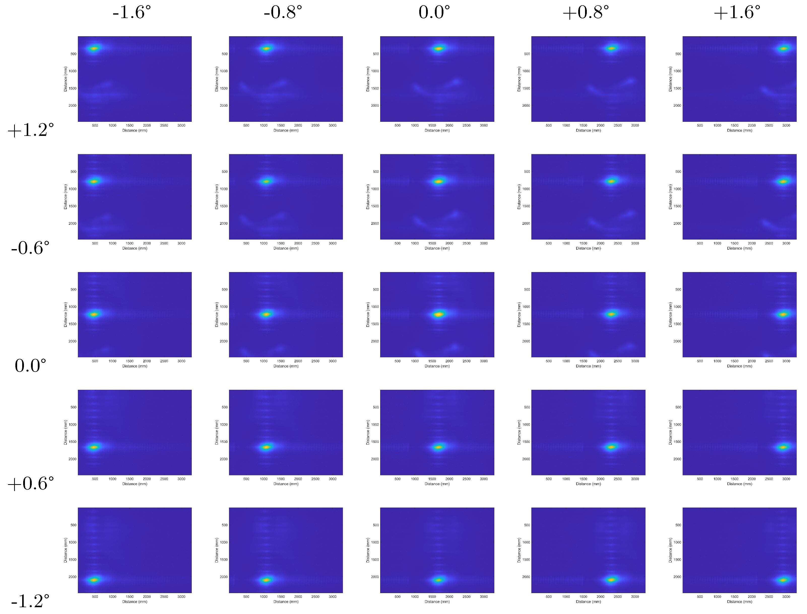
Figure 17 illustrates the off-axis images of the LE module with a focal length of 400 mm for energy 4.5 keV. The figure shows focal spot images on the detector for various positions of the optics, corresponding to off-axis angles of approximately ±1.6° in the horizontal direction and ±1.2° in the vertical direction.
The measurements confirm this performance in
Figure 18, which shows the percentage changes in full width at half maximum (FWHM) compared to the on-axis focal spot. The FWHM varied by no more than ±3.5% in the vertical direction and ±4.5% in the horizontal direction, indicating excellent off-axis imaging stability and minimal degradation in resolution.
Off-axis imaging (
Figure 17) characterizes the FWHM and blur as a function of field angle (
Figure 18). By contrast, the FOV (
Figure 15 and
Figure 16) reported here is the range of incidence angles for which the focus image remains on the active detector area and the detected flux is above the usable signal value. Consequently, off-axis imaging describes the image quality (focus blurring), while the FOV edge is set primarily by geometric throughput limits rather than by a specific FWHM criterion.
6.6. Effective Area and Gain
The effective area varies with the photon energy and can be determined using different methods. In this study, we calculated the effective area of the optical system using the following equation:
Here, I represents the integral sum of all counts:
is the total count from the dark image (X-ray source off);
is the total count from the reference image (X-ray source on, without optics);
is the total count from the measured image with optics.
The detector area (
) for the Rigaku camera is 2.43 cm
2. The geometric correction factor
accounts for the divergence of the X-ray beam. Calculated using the distances between the source and the optics (
) and between the source and the detector (
).
The effective area was calculated for three energies. The gain was also calculated on the basis of the integrated signal counts.
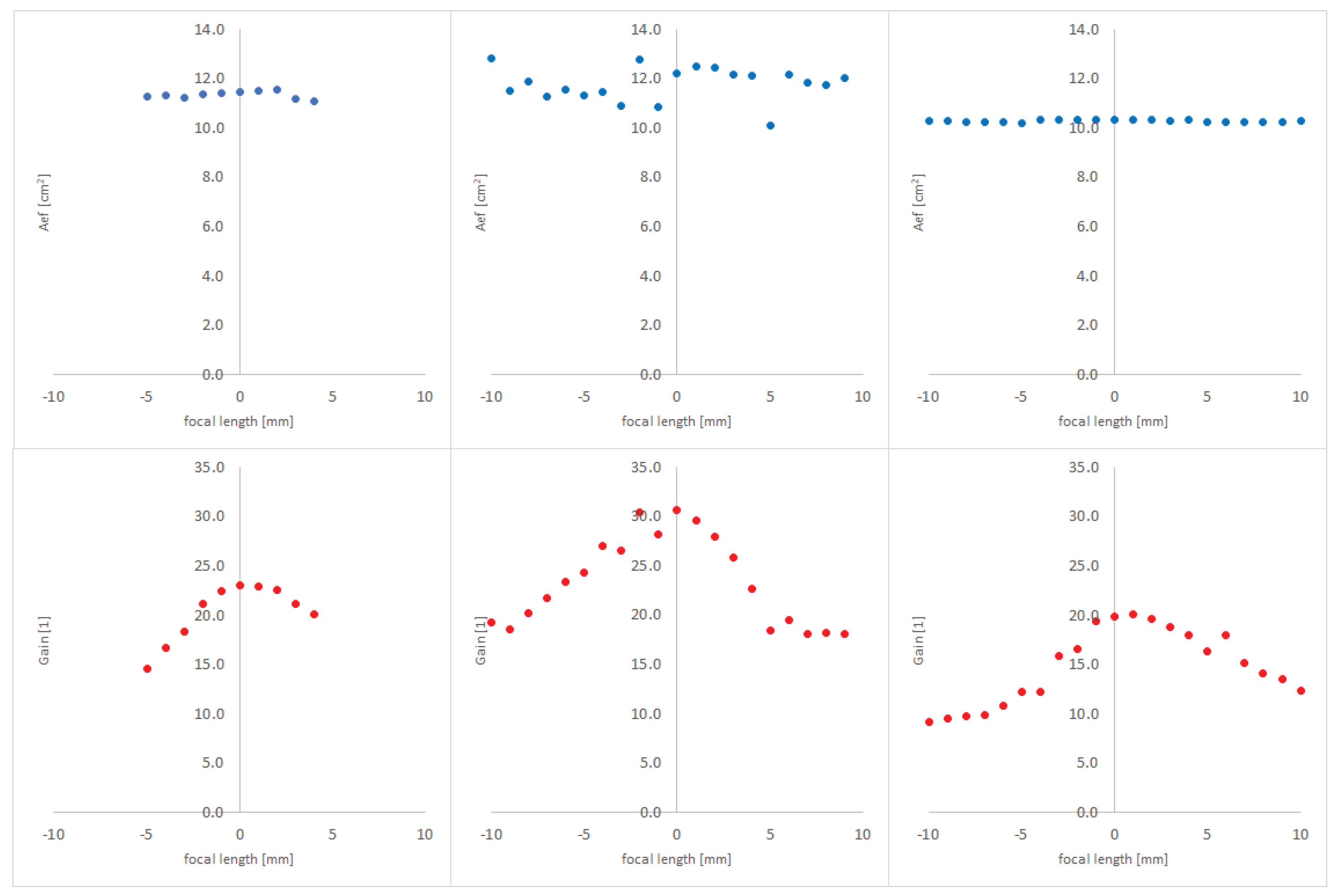
The effective area measured is approximately 11.5 cm
2 for energies in the range of 0.85–3 keV and 10.3 cm
2 for 4.5 keV. These measurements confirm the assumption that the effective area decreases with increasing photon energy (
Figure 19).
The gain
G was calculated as the ratio of the global maximum in the optical
to the mean of the reference
(source image—without the optics). This yields the peak-based gain of the optics relative to the average level of the direct beam. The gain was calculated using the following equation.
where ROI (Region of Interest) denotes a fixed subregion of the image containing the spot. The same ROI was used for the optics and reference images. Both ROIs were background corrected
.
7. One-Dimensional Versus Two-Dimensional
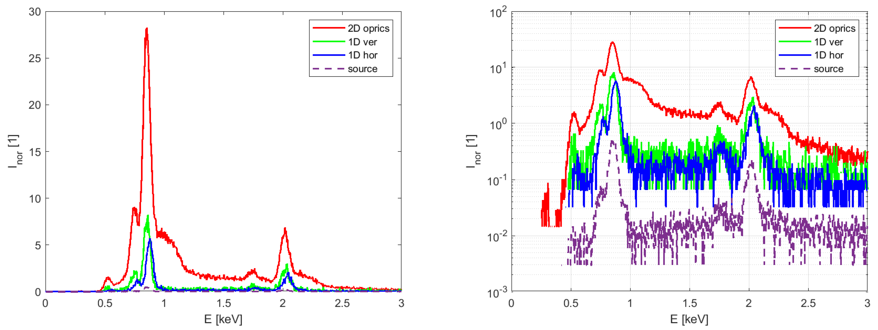
One-dimensional submodules and a two-dimensional optical configuration were compared in terms of spectral intensity enhancement using a spectrometer. The two-dimensional (2D) optics, as well as the one-dimensional (1D) horizontal (submodule A) and vertical (submodule B) optical modules, were evaluated (
Figure 20). The X-ray tube with the NiP target was fixed in position, while the optics were placed at the focal point of the system. The spectrometer was mounted on motorized translation stages (X, Y, and Z). Measured data were normalized for comparison. Specifically, the data obtained with the NiP target were normalized to the peak around 7.5 keV. The NiP target with three energy lines was used as the X-ray source. The first peak (around 1 keV) and the second peak (around 2.0 keV) from the 1D submodules, 2D optics, and the direct beam were compared.
The experiment confirmed the theoretical assumptions regarding the performance of the optics. It was shown that the benefit of the 2D optics is approximately 110 times greater at energies around 1 keV and about 13 times greater at 2 keV (in terms of gain), compared to a system without any optics.
8. Discussion
The experimental results confirm the suitability of the Schmidt-type 2D Lobster Eye (LE) X-ray optics for CubeSat-based astronomical applications. Compared to earlier LE implementations, the presented system achieves a competitive angular resolution (10 arcmin), a wide field of view (>8 deg at 4.5 keV), and an effective area of approximately 11.5 cm2 in the 2–3 keV energy range.
One of the most notable advantages is the demonstrated off-axis stability (see
Figure 17), with only 3.5% (vertical) and 4.5% (horizontal) degradation in FWHM across the field of view. This is crucial for wide-field sky monitoring missions, where uniform image quality is essential. Previous studies have suggested similar performance in simulations, but this work validates these findings experimentally in a laboratory vacuum setup.
In addition, the optical system benefits from the modular 2D MFO design, where two orthogonal 1D modules provide cross-shaped focal spots. This configuration offers significantly higher gain than 1D modules alone (by up to a factor of 110 at 1 keV), as verified via spectrometric measurements (see
Figure 20).
Based on the results presented in this paper, the unique combination of a pixel detector and an SDD spectrometer designed for the SR-CTP demonstrator has proven to be highly effective. This hybrid detection approach enables simultaneous imaging and spectroscopy, with a combined spectral coverage from approximately 0.5 keV up to 30 keV. Such capability is particularly advantageous for observing transient X-ray phenomena, where both spatial and spectral information are crucial.
In summary, this work represents a significant step toward a miniaturized wide-field X-ray monitor suitable for CubeSats. Future work should focus on space qualification, long-term mechanical stability, radiation hardness, and performance validation in a high-energy test facility such as the PANTER facility.
9. Conclusions
We have presented the design, manufacturing, and experimental validation of a compact Schmidt-type 2D Lobster Eye (LE) X-ray optics system based on Multi-Foil Optics (MFO), developed for CubeSat applications within the ESA SR-CTP project. The system was characterized in a laboratory vacuum setup (10 m long) using multiple X-ray targets and detectors.
Key optical parameters, such as focal length, angular resolution, effective area, and field of view, were experimentally verified and found to be consistent with simulation predictions.
These results confirm the readiness of the optical payload for integration into the CubeSat demonstrator. The next phase of the project will involve full-system testing at the PANTER facility, Max Planck Institute for Extraterrestrial Physics, Germany, to assess performance under realistic space-like conditions. This paper presents one of the first experimental confirmations in a compact CubeSat form.

