Abstract
Three-dimensional holographic imaging technology is increasingly applied in biomedical detection, materials science, and industrial non-destructive testing. Achieving high-resolution, large-field-of-view, and high-speed three-dimensional imaging has become a significant challenge. This paper proposes and implements a three-dimensional holographic imaging method based on trillion-frame-frequency all-optical multiplexing. This approach combines spatial and temporal multiplexing to achieve multi-channel partitioned acquisition of the light field via a two-dimensional diffraction grating, significantly enhancing the system’s imaging efficiency and dynamic range. The paper systematically derives the theoretical foundation of holographic imaging, establishes a numerical reconstruction model based on angular spectrum propagation, and introduces iterative phase recovery and image post-processing strategies to optimize reproduction quality. Experiments using standard resolution plates and static particle fields validate the proposed method’s imaging performance under static conditions. Results demonstrate high-fidelity reconstruction approaching diffraction limits, with post-processing further enhancing image sharpness and signal-to-noise ratio. This research establishes theoretical and experimental foundations for subsequent dynamic holographic imaging and observation of large-scale complex targets.
1. Introduction
With the continuous advancement of modern science and technology, obtaining precise structural information and dynamic evolution patterns of complex objects in three-dimensional space has become a critical requirement across numerous fields [1,2]. In biomedicine, 3D imaging assists physicians in performing non-invasive in vivo diagnostics and pathological analysis [3,4,5]. In industrial inspection, 3D topography measurement provides reliable foundations for product quality control and defect identification [6,7,8]. In fluid mechanics and plasma physics, 3D dynamic observation is essential for understanding complex motion processes [9,10]. Traditional two-dimensional imaging technologies, limited to providing projection information, struggle to meet the demands of these applications for full-information, high-resolution, and real-time capabilities. Consequently, three-dimensional holographic imaging has emerged as a frontier and hotspot in recent research.
The fundamental principle of holographic imaging was first proposed by Gabor in 1948 [11,12]. Its core concept lies in recording and reproducing both the amplitude and phase information of the object light. By superimposing the object light with a reference light on the recording surface, the three-dimensional information of the object can be encoded within the interference pattern. Subsequent reconstruction relies on optical or numerical methods to analyze the hologram, thereby restoring the object’s spatial structure. Compared to traditional imaging methods, holography’s greatest advantage lies in its ability to achieve full-information recording—simultaneously capturing both amplitude and phase information—making it uniquely valuable for precision measurement and 3D reconstruction [13,14,15]. However, conventional holographic imaging methods still face significant limitations in practical applications. First, imaging speed is constrained. The frame rate of conventional detectors is insufficient for observing high-speed dynamic processes, such as intracellular transient reactions, ultrafast fluid motion, or laser plasma evolution [16]. Second, the trade-off between resolution and field of view has long constrained system performance. Due to the finite spatial bandwidth of detectors, pursuing high resolution often sacrifices field of view, and vice versa, resulting in poor imaging performance for large-scale targets [17]. Third, insufficient signal-to-noise ratio becomes particularly pronounced with weak-signal samples or complex scatterers [18,19]. Reconstructed images are often plagued by noise and artifacts, rendering them unsuitable for quantitative analysis and precision measurements.
To address the aforementioned issues, scholars worldwide have proposed various improvement strategies. For instance, the off-axis holographic method introduces an angle in the reference light to separate the real image and its conjugate image in the frequency domain, thereby effectively mitigating the twin-image problem [20,21,22,23]. Phase-shift digital holography, meanwhile, enhances the accuracy and stability of phase reconstruction by superimposing multiple phase-shift holograms [24,25,26]. However, off-axis structures reduce spatial bandwidth utilization, while phase-shifting methods require multiple exposures, limiting their application in high-speed dynamic scenarios. In recent years, with advancements in computational optics and algorithm optimization, numerical propagation-based multi-plane phase recovery methods have garnered significant attention [27,28,29,30]. This approach achieves high-quality reconstruction with a single exposure by utilizing multi-plane intensity constraints, yet it still suffers from issues such as noise sensitivity and insufficient robustness. Phase retrieval from multi-plane intensity measurements has been extensively investigated in the field of digital holography and computational imaging. A variety of algorithms have been developed to recover complex wavefronts from intensity-only data, including Gerchberg–Saxton-type iterative methods [31], transport-of-intensity approaches [32], and angular-spectrum-based multi-plane propagation techniques. To overcome the limitations of single-plane constraints, Pedrini proposed reconstructing the optical wavefront from a sequence of interferograms recorded at multiple propagation planes, which established the experimental basis for intensity-only wavefront recovery [33]. Almoro further extended this framework by introducing sequential intensity measurements of volume speckle fields, achieving complete wavefront reconstruction without reference interference [34]. Subsequent studies have focused on enhancing algorithmic robustness and spatial diversity. Almoro introduced a deformable mirror to produce single-plane multiple speckle diversities for improved convergence stability [35]. Migukin formulated multi-plane phase retrieval as a variational optimization problem under intensity-only Gaussian noise, yielding more stable solutions [36]. Buco et al. applied adaptive intensity constraints to accelerate convergence and suppress noise amplification [37], while Xu et al. demonstrated that using unequal inter-plane distances can further enhance detail reconstruction and convergence efficiency [38]. Together, these works form the foundation for modern computational holography, illustrating that multi-plane intensity constraints significantly improve the fidelity and stability of numerical phase retrieval.
Against this backdrop, this paper proposes and implements a trillion-frame frequency-domain all-optical three-dimensional holographic imaging method. The core innovations of this method include the following aspects: A strategy combining spatial and temporal multiplexing is employed in the optical architecture innovation. This method utilizes two-dimensional diffraction gratings and filters to achieve segmented acquisition of wide-spectrum light fields, thus overcoming the limitations of the spatial-bandwidth product of traditional detectors. An iterative phase recovery framework based on angular spectrum propagation is proposed in the algorithm optimization. By imposing consistency constraints on multiple propagation distances, the phase ambiguity problem in single-frame intensity measurement is effectively alleviated. In terms of post-processing enhancement, a dual-channel post-processing strategy is proposed for the different characteristics of amplitude and phase. This method achieves significant improvements in objective indicators while improving visual image quality.
2. Theory and Experiment
2.1. Theory
The fundamental concept of three-dimensional holographic imaging lies in simultaneously encoding the amplitude and phase information of an object into a single intensity image by recording the interference fringes between the object light and the reference light. This enables the reconstruction of the object field through numerical propagation and phase recovery algorithms. In a typical coaxial holographic experimental setup, the object light and the reference light interfere at the recording plane to form an interference pattern [39,40]. According to the principle of superposition, the light field intensity on the recording surface can be expressed as:
where two of these cross-components carry the object light phase. Since CCD/CMOS sensors are only sensitive to intensity, phase cannot be directly measured and must be restored during the reconstruction phase. During numerical reconstruction, the hologram is illuminated with reconstructed light, and the transmitted (or diffracted) field contains three components: a DC background, the true image, and the conjugate image. In coaxial structures, these three components overlap in the frequency domain, making separation through simple spectral filtering difficult. This makes twin image suppression and phase recovery critical to system success. In contrast, off-axis structures rely on carrier frequencies to achieve separation in the frequency domain, but this comes at the cost of sacrificing effective spatial bandwidth. The subsequent theory and algorithms in this paper focus on stable reconstruction under coaxial configurations. To numerically describe the free-space propagation of light fields and achieve three-dimensional reconstruction, this paper employs the Angular Spectrum Method (ASM) [41,42,43]. This method performs a two-dimensional Fourier transform on the incident field to obtain the angular spectrum . This spectrum is then multiplied in the frequency domain by the propagation transfer function:
Thus, the angular spectrum at propagation distance z is obtained as:
By applying the inverse Fourier transform, the light field distribution at propagation distance is obtained as:
where represents the wave number, and represents the wavelength of the incident light. Furthermore, the square root term in the above formula corresponds to the propagation phase factor in free space. For the high-frequency portion satisfying , the propagation factor becomes imaginary, and the corresponding spatial frequency component exhibits exponential attenuation, physically corresponding to an evanescent wave. ASM is equally applicable to both near-field and far-field scenarios and can be efficiently implemented using FFT, making it highly suitable for batch processing and three-dimensional calculations in digital holography. Considering the numerical aperture and pixel sampling conditions of this system, we employ a band-limited angular spectrum strategy in our implementation to mitigate high-frequency folding and noise amplification introduced by discrete sampling, thereby ensuring the stability of the propagation operator.
Phase recovery remains a core challenge in coaxial digital holography. Single-plane Gerchberg–Saxton (GS) iterations are prone to local minima convergence when noise or model mismatch exists, and struggle to fully suppress twin images [44]. To address this, this paper introduces a multi-plane intensity consistency constraint: by acquiring high-precision axial scans of intensity at multiple defocus distances z, the object plane complex field is solved using an objective function that minimizes data consistency while incorporating prior regularization:
The first term ensures consistency between the reconstruction field and experimental measurements across multiple planes, while the second term represents a priori regularization, where is the regularization weight. We treat angular spectrum propagation as a forward operator, introducing multi-plane constraints within the alternating steps of “forward propagation-amplitude replacement-backward propagation.” Regularization terms are handled using either the Alternating Direction Method of Multiples (ADMM) or Proximal Gradient Decomposition (PGD) mechanism, ensuring data consistency and prior constraints are satisfied in each iteration. Comparative results from practical optimization are presented in Section 3.
2.2. Experimental
To validate the applicability of the aforementioned theoretical model and reconstruction algorithm in real-world systems, we constructed a femtosecond laser-based coaxial digital holographic platform. Experiments were conducted around a closed-loop system comprising light source and broadening, beam splitting and spatial division, sample loading, spectral imaging and recording, and multi-plane acquisition strategies. The system design aimed to balance broadband multiplexing and spatial sectioning capabilities while maintaining coherence and stability, achieving sufficient sampling rates and dynamic range at the detection end to support the numerical conditions for 3D reconstruction.
The experimental optical setup is shown in Figure 1. The light source and broadening stage employed a Ti:sapphire femtosecond amplification system delivering ultrashort pulses centered at 755 nm with a pulse width of approximately 230 fs. To achieve the desired temporal stretching and spectral broadening, the pulse successively passed through 350 mm of SF11 glass and 300 mm of SF10 glass (positive dispersion), yielding an effective pulse duration of about 1.5 ps. This broadband time–frequency expansion facilitated spatial multiplexing while minimizing temporal distortion induced by nonlinear effects. The beam was then collimated and shaped via dielectric mirrors, and an adjustable aperture was used to suppress higher-order diffraction and stray light, ensuring high spectral purity at the source.

Figure 1.
Schematic Diagram of the Experimental Optical Path. Ti:sapphire femtosecond laser (755 nm, 230 fs), SF11 (350 mm) and SF10 (300 mm) dispersion media, a 2 × 2 Dammann diffraction grating (DOE) with ~80% efficiency, narrow-band filters positioned at the 4f spectral plane, a 4f imaging system composed of two achromatic lenses with focal lengths of 75 mm, and a CCD camera (3648 × 5472 pixels, 2.4 µm pixel size, 12-bit dynamic range).
In the beam-splitting and spatial/frequency-division module, the incident beam illuminated a 2 × 2 Dammann diffraction grating (DOE) designed for 755 nm operation, producing four uniform diffraction spots with an efficiency of approximately 80% and channel uniformity deviation below 5%, the grating design is shown in Figure A1. The zero-order diffraction was spatially filtered at the Fourier plane to prevent background interference and maintain balanced energy distribution. Narrow-band interference filters were placed at the 4f spectral plane according to diffraction orders, enabling combined spatial–frequency multiplexing that preserves coherence within each sub-channel while enhancing parallel acquisition capability. A photo of the optical path setup is shown in Figure A2.
After interaction with the sample, the light field entered the spectral imaging and recording module, where a 4f system projected the spectrally encoded sub-beams onto the detection plane. A CCD camera (resolution = 3648 × 5472 pixels, pixel size = 2.4 µm × 2.4 µm, 12-bit dynamic range, 6 fps) captured multi-plane intensity distributions with near-diffraction-limited spatial sampling. To further improve image uniformity, each frame was corrected using flat-field calibration and background subtraction to compensate for pixel nonuniformity and low-frequency environmental scattering. All optical elements were mounted on a vibration-isolated optical bench, and alignment was verified through a precision micrometer stage to maintain long-term stability. This configuration effectively balanced computational load with data redundancy, improved convergence of phase retrieval, and established a robust foundation for subsequent studies, including those assessing the influence of DOE design and frame reduction on 3D reconstruction quality.
According to the experimental parameters, we know that the rate originates from the optical time–wavelength mapping mechanism in the system. The broadening of a femtosecond pulse in a dispersive medium can be expressed as
where is the accumulated group delay dispersion. When a pulse with a central wavelength of 755 nm and a pulse width of 230 fs passes through a 0.35 m SF11 and a 0.30 m SF10, the pulse width broadens to approximately 1.5 ps. After filtering with a 2.2 nm bandwidth, the shortest equivalent exposure time for a single channel is approximately 976 fs. The temporal recording window and the inter-channel temporal separation are determined by the wavelength-to-time conversion relations:
where D is the dispersion parameter, z is the propagation distance within the disperse medium, and and denote the overall spectral window and the wavelength spacing between adjacent channels, respectively. With and , the corresponding temporal recording length and inter-frame delay are calculated to be and . Accordingly, the effective optical frame rate of the system can be defined as
3. Results and Discussions
As described in the theoretical section, in an on-axis holographic system, the light from the object and its conjugate image propagate in the same direction. This prevents their complete separation in the spatial frequency domain, leading to the phenomenon of “ghosting.” While this characteristic poses challenges for phase recovery, the on-axis structure offers higher spatial bandwidth utilization compared to off-axis holography, enabling full utilization of the detector’s sampling potential. Therefore, we first compare the off-axis and on-axis holographic spectra, as shown in Figure 2.
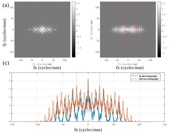
Figure 2.
Comparison of coaxial and off-axis holographic spectra. (a) Coaxial holographic spectrum. (b) Off-axis holographic spectrum. (c) Comparison of spectral center cross-sections.
As shown in the figure, under coaxial conditions, the intensity of the recording plane is . Its Fourier spectrum can be decomposed into the sum of the zero-order DC term , the autocorrelation term , and the cross-term near the origin and . Since the reference light is an in-plane wave along the axis, the cross-term carries no carrier frequency [45,46]. Consequently, it strongly overlaps with the zero-order term and the conjugate term at the center of the frequency domain (Figure 2a), manifesting as highly concentrated energy near the origin and a steep spectral dynamic range (the “coaxial” curve in Figure 2c exhibits a sharp peak). This overlap makes it difficult to effectively separate the true image from the conjugate image using simple bandpass filtering. It is the fundamental reason why “twin images” and strong zero-order background are difficult to suppress in coaxial holographic reproduction.
In contrast, the off-axis geometry introduces a carrier frequency onto the reference light, causing the intensity cross-term to shift in the frequency domain around . Figure 2b (right) clearly shows symmetrical energy peaks appearing at (marked by red dashed lines in the text), achieving significant spatial frequency separation from the zero-order DC component. The central row slice in Figure 2c similarly exhibits a double-peak structure at . This separation enables the sideband corresponding to the true image to undergo narrowband pass filtering and spectral shifting for alias-free reconstruction. This effectively suppresses contamination from the zero-order and conjugate images, significantly enhancing the signal-to-noise ratio and contrast of the reproduced image.
Trillion-frame three-dimensional holographic imaging reconstruction employs angular spectrum diffraction theory. Figure 3 illustrates the evolution of light field distribution at different propagation distances based on the angular spectrum method. The amplitude component reveals that the initial field retains a morphology similar to the object plane aperture in the near field . As the propagation distance increases, the light field gradually undergoes diffraction broadening, with edges becoming blurred and energy diffusing outward. When propagation reaches the millimeter scale, the spot size significantly enlarges, local details gradually vanish, and typical far-field diffusion characteristics emerge. The phase distribution reveals the phase evolution patterns of the light field during free-space propagation. Within the near-field range, phase fluctuations primarily correlate with the initial object-light structure. As propagation distance increases, phase fringes gradually tend toward concentric arc-shaped or radial distributions, reflecting the evolution trend of spherical wavefronts. Overall, the simulation results visually demonstrate that the angular spectrum method can accurately describe the continuous transition of the light field from near-field to far-field. This provides theoretical justification and method validation for holographic reconstruction and three-dimensional light field analysis based on numerical propagation.

Figure 3.
Light field simulation results at different propagation distances.
For the final phase recovery, we propose an iterative phase recovery framework based on angular spectrum propagation. This framework combines the free-space propagation process of light waves with numerical optimization, progressively correcting lost phase information during the iteration. Figure 4 presents a comparison of simulated reconstruction results from three typical phase recovery algorithms under the angular spectrum propagation model and Poisson noise conditions. It can be observed that while the single-plane Gerchberg–Saxton (GS) method can recover the general outline of the target, the inherent ill-posedness of single-view intensity measurements results in noticeable ghosting and noise ringing in the reconstruction. This leads to significantly low amplitude PSNR/SSIM values and a phase RMSE as high as 1.45 rad. The Multi-plane Alternating Projection (MP-AP) method effectively mitigates ambiguity by introducing amplitude consistency constraints across multiple propagation distances. This significantly improves amplitude metrics (PSNR = 22.0, SSIM = 0.841) and reduces phase RMSE to 1.41 rad, though residual local artifacts and streaks remain observable. In contrast, Multi-plane TV-Regularized Proximal Gradient (MP-TV-PGD) imposes a total variation constraint in the object domain, effectively suppressing high-frequency noise and artifacts while preserving overall structure. This approach significantly reduces phase RMSE to 0.96 rad, demonstrating higher phase recovery accuracy. However, constrained by the smoothing effect of regularization, the amplitude PSNR (21.6) and SSIM (0.822) were slightly lower than those of MP-AP. In summary, multi-plane propagation combined with appropriate regularization can significantly enhance the robustness and accuracy of phase recovery while ensuring amplitude fidelity. Different algorithms exhibit distinct advantages in amplitude and phase metrics.
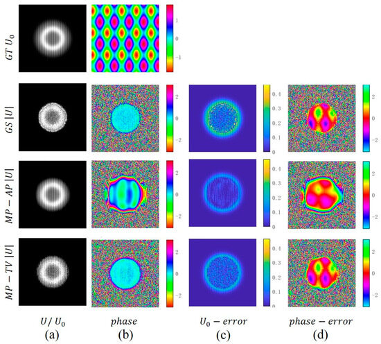
Figure 4.
Comparison of Phase Recovery Performance Under Simulated Data. (a) Amplitude. (b) Phase. (c) Amplitude-error. (d) Phase-error.
After completing the optical system setup and data acquisition, this paper conducted experimental validation using resolution charts. The experimental results centered on evaluating two-dimensional imaging performance, multi-plane holographic reconstruction, and post-processing effects, with a systematic discussion of the method’s performance based on quantitative metrics.
In the resolution plate experiment, we first evaluated the system’s two-dimensional imaging performance at the focal plane, as shown in Figure 5. After broadening, beam splitting, and filtering, the femtosecond laser illuminated a standard resolution plate. The transmitted image recorded by the CCD clearly demonstrated aperture effects: without an aperture, the image background exhibited visible scattered fringes and low-frequency fluctuations, resulting in insufficient high-frequency line contrast. When an aperture was introduced into the optical path, stray components were effectively suppressed, the background flattened, high-frequency line edges exhibited steeper transitions, and overall clarity significantly improved. Estimations matching the system’s pixel scale and magnification indicate a lateral resolution approaching 2.8 μm, consistent with the observed ability to resolve the finest lines. Objective evaluation based on the same dataset further supports this observation: under identical conditions, introducing an aperture ring increased the signal-to-noise ratio from approximately 36.4 dB to 44.6 dB, while the structural similarity index rose from about 0.78 to 0.91. This demonstrates that spectral clipping and stray light suppression provide a direct and stable contribution to enhancing high-frequency structures and suppressing background fluctuations.
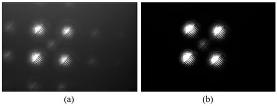
Figure 5.
Experimental results of coaxial holographic two-dimensional imaging. (a) Imaging results without an aperture. (b) Imaging results with an aperture.
To achieve high spatio-temporal resolution 3D reconstruction, we set multiple defocus positions in front of and behind the object plane during the experiment, pro-gressively acquiring defocus holograms. Using a precision displacement stage to con-trol the distance between the CCD and the sample, we recorded continuous defocus patterns at 100 μm increments, capturing multi-plane intensity distributions spanning from the focal point to the far-focus position. The acquisition of defocused holograms essentially captures angular spectra of the object field at varying propagation distances, providing redundant information essential for phase recovery. As shown in Figure 6, typical defocused holograms exhibit distinct interference fringe structures, with fringe spacing progressively decreasing as defocus increases. These interference fringes con-tain phase-modulated information of the object’s complex amplitude, providing foun-dational data for subsequent phase recovery and 3D reconstruction. Prior to formal re-construction, all images undergo preprocessing operations such as flat-field correction and background removal to eliminate detector response inhomogeneities and external optical noise, ensuring the accuracy and consistency of holographic data. The figure displays four representative defocused holograms. As the defocus distance increases from near to far, the fringes become progressively denser and the interference contrast gradually intensifies. This clearly reveals the spatial frequency evolution pattern in-duced by defocusing, which directly reflects the phase modulation characteristics of the object-image wavefront.
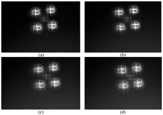
Figure 6.
Defocused hologram. (a) 500 um. (b) 1000 um, (c) 1500 um. (d) 2000 um.
Based on the collected multi-plane defocused holographic data, the object’s complex amplitude field is numerically reconstructed using angular spectrum propagation combined with an iterative phase recovery algorithm. The reconstruction process involves multiple iterations of forward and backward propagation in the frequency domain, progressively optimizing the complex amplitude distribution of the object field through combined intensity and phase constraints. Figure 7 presents the overall reconstruction result of the resolution plate. As shown in Figure 7a, the reconstructed image effectively restores the structural information of the resolution plate, with the stripe distribution exhibiting high consistency with the experimental object. This demonstrates that the adopted algorithm achieves high-fidelity reproduction of the object’s two-dimensional projection information under static conditions. Furthermore, the experiment separately extracted and analyzed the amplitude component of the wavefield. As shown in Figure 7b, the reconstructed amplitude exhibits intensity distribution characteristics consistent with the geometric structure of the resolution plate in the grayscale image. The pseudocolor image provides a more intuitive observation of signal intensity contrasts across different regions. Particularly in the high-frequency stripe areas, the system’s imaging performance after stray light suppression becomes evident, with sharper edge transitions. The recovery of amplitude information not only validates the accuracy of the two-dimensional imaging experiment but also provides reliable amplitude constraints for subsequent phase reconstruction. In addition to amplitude information, the experiment also reconstructed the phase distribution of the object field. In addition, we conducted a three-dimensional particle field holographic experiment, as shown in Figure A3. Therefore, the trillion-frame-frequency all-optical three-dimensional holographic imaging method proposed in this paper demonstrates promising potential in theoretical modeling, algorithm design, and experimental validation. With further advancements in optical design, algorithm optimization, and hardware technology, this method is expected to play a significant role in broader scientific and engineering applications, including biomedicine and ultrafast dynamics.
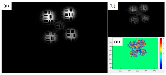
Figure 7.
(a) Holographic image reproduction. (b) Reconstruction amplitude. (c) Phase reconstruction.
4. Conclusions
This paper proposes and systematically validates a three-dimensional holographic imaging method based on trillion-frame all-optical phase division. Theoretically, the holographic imaging principle is derived and an angular spectrum propagation model is established. Algorithmically, an iterative phase recovery framework combining multi-plane intensity consistency with total variation regularization is introduced. Experimentally, imaging tests using resolution plates and static particle fields demonstrate the method’s effectiveness and robustness under static conditions. For post-processing, the proposed dual-channel enhancement strategy for amplitude and phase further improves image clarity and signal-to-noise ratio. Therefore, the proposed trillion-amplitude all-optical frame-by-frame 3D holographic imaging method demonstrates promising potential in theoretical modeling, algorithm design, and experimental verification. With further advancements in optical design, algorithm optimization, and hardware technology, this method is expected to play a significant role in a wide range of scientific and engineering applications, including biomedicine and molecular dynamics.
Author Contributions
Conceptualization, Y.Z., Q.L., W.Z. and Z.L.; data curation, Y.Z. and Q.L.; formal analysis, Y.Z., Q.L. and Z.L.; methodology, Y.Z., Q.L., W.Z. and Z.L.; resources, Z.L.; software, Y.Z.; data curation, Y.Z. and Q.L.; writing—original draft preparation, Y.Z.; writing—review and editing, Y.Z., W.Z. and Z.L.; funding acquisition, Z.L. All authors have read and agreed to the published version of the manuscript.
Funding
This work was supported by the Promotion Project of Scientific Research Capability of Key Construction Disciplines in Guangdong Province (2022ZDJS118) and Shenzhen University of Technology to Introduce new high-end talent financial subsidy research Project (GDRC202201).
Institutional Review Board Statement
Not applicable.
Informed Consent Statement
Not applicable.
Data Availability Statement
Data available on request from the authors.
Conflicts of Interest
The authors declare no conflicts of interest.
Appendix A
In this study, a 2 × 2 Dammann diffraction grating (DOE) was employed to achieve multi-channel beam splitting. The DOE was designed for a central wavelength of 755 nm and generated four evenly distributed diffraction spots in a square array, corresponding to four independent optical sub-channels. The angular separation between adjacent diffraction orders was θsx = θsy = 2.24°, and the maximum diffraction angle reached θmax = 9.5°, as illustrated in Figure A1.
The DOE was fabricated with a binary π-phase modulation, optimized for equal-energy output. The first-order diffraction efficiency was measured to be approximately 80%, and the intensity non-uniformity among the four channels was below ±5%. The zero-order diffraction was spatially blocked in the Fourier plane to suppress background and improve inter-channel contrast.
This 2 × 2 configuration was chosen to balance angular separation, energy uniformity, and broadband stability. It provides sufficient isolation among diffracted beams while maintaining high optical throughput. Although higher-order Dammann gratings (3 × 3, 4 × 4) can theoretically increase the number of channels, their stronger wavelength sensitivity may compromise uniformity. The proposed 2 × 2 DOE thus offers an optimal balance between efficiency and system robustness for the present experimental conditions.
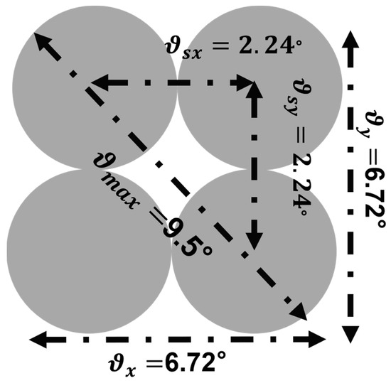
Figure A1.
Damann Grating Diffraction Pattern.
Appendix B
The system consists of five sequentially interlocked modules: (1) light source and temporal broadening, (2) beam splitting and spatial–spectral division, (3) sample loading, (4) spectral imaging and recording, and (5) multi-plane acquisition and reconstruction. Major optical components include a Ti:sapphire femtosecond laser (755 nm, 230 fs), SF11 (350 mm) and SF10 (300 mm) dispersion media, a 2 × 2 Dammann diffraction grating (DOE) with ~80% efficiency, narrow-band filters positioned at the 4f spectral plane, and a CCD camera (3648 × 5472 pixels, 2.4 µm pixel size, 12-bit dynamic range). The zero-order diffraction is spatially filtered at the Fourier plane to ensure uniform energy distribution among the four effective sub-channels.
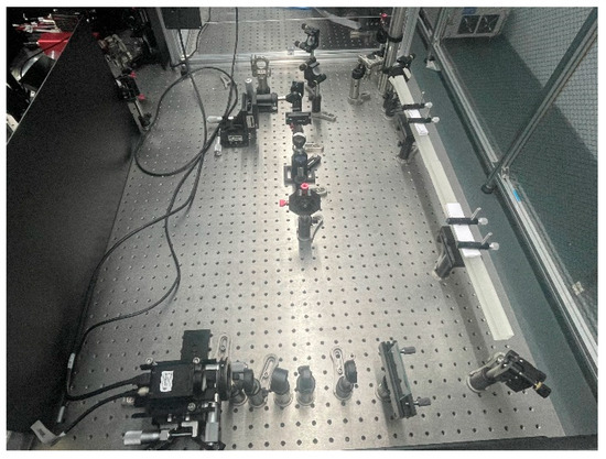
Figure A2.
Photograph of the femtosecond laser–based coaxial digital holographic experimental platform.
Appendix C
To verify the robustness and reliability of the system, the two-dimensional imaging performance of the particle field was evaluated. The experimental light source was a femtosecond laser, which illuminated the sample after broadening and filtering, and a CCD camera was used to record the transmission image. The experimental results show that particle size has a significant impact on imaging quality. For particles with a diameter of 50 μm, due to their large size, the scattering cross-section is significantly increased, the imaging signal intensity is high, and a strong bright spot appears on the CCD with a clearer boundary outline. The experimental results show that the particle field can still be clearly resolved, indicating that the system maintains good stability under high dynamic range conditions. After acquiring multi-plane defocused holograms, the particle field was numerically reconstructed using angular spectrum propagation combined with an iterative phase retrieval algorithm. This algorithm performs multiple forward and backpropagation iterations in the frequency domain, gradually optimizing the complex amplitude distribution of the object field, thereby achieving high-fidelity recovery of the particle field. Experimental results show that for 50 μm particles, the reconstruction results have a high signal-to-noise ratio, complete and clear particle boundary outlines, and accurate restoration of inter-particle distribution characteristics, demonstrating the system’s robustness and adaptability under a wide range of lighting conditions.
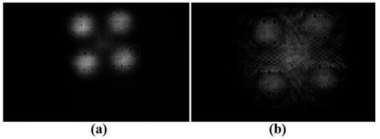
Figure A3.
Particle field holography experiment: (a) 2D particle field photo; (b) 3D particle field reconstruction.
References
- Kaiser, A.; Ybanez Zepeda, J.A.; Boubekeur, T. A Survey of Simple Geometric Primitives Detection Methods for Captured 3D Data. Comput. Graph. Forum 2019, 38, 167–196. [Google Scholar] [CrossRef]
- Wang, Z.; Miccio, L.; Coppola, S.; Bianco, V.; Memmolo, P.; Tkachenko, V.; Ferraro, P. Digital holography as metrology tool at micro-nanoscale for soft matter. Light Adv. Manuf. 2022, 3, 151–176. [Google Scholar] [CrossRef]
- Chuang, S.C.; Yu, S.A.; Hung, P.C.; Lu, H.T.; Nguyen, H.T.; Chuang, E.Y. Biological Photonic Devices Designed for the Purpose of Bio-Imaging with Bio-Diagnosis. Photonics 2023, 10, 1124. [Google Scholar] [CrossRef]
- Tian, M.; He, X.; Jin, C.; He, X.; Wu, S.; Zhou, R.; Zhang, X.; Zhang, K.; Gu, W.; Wang, J.; et al. Transpathology: Molecular Imaging-Based Pathology. Eur. J. Nucl. Med. Mol. Imaging 2021, 48, 2338–2350. [Google Scholar] [CrossRef]
- Zhou, Y.; Nakagawa, A.; Sonoshita, M.; Tearney, G.J.; Ozcan, A.; Goda, K. Emergent photonics for cardiovascular health. Nat. Photon 2025, 19, 671–680. [Google Scholar] [CrossRef]
- Huang, K.; Wu, X.; Lin, Z. An Advanced Laboratorial Measurement Technique of Scour Topography Based on the Fusion Method for 3D Reconstruction. J. Ocean. Eng. Sci. 2025, 10, 322–329. [Google Scholar] [CrossRef]
- Deng, Q.; Zhan, Y.; Liu, C.; Qiu, Y.; Zhang, A. Multiscale power spectrum analysis of 3D surface texture for prediction of asphalt pavement friction. Constr. Build. Mater. 2021, 293, 123506. [Google Scholar] [CrossRef]
- Zhou, L.; Wu, G.; Zuo, Y.; Chen, X.; Hu, H. A Comprehensive Review of Vision-Based 3D Reconstruction Methods. Sensors 2024, 24, 2314. [Google Scholar] [CrossRef] [PubMed]
- Park, H.K.; Choi, M.J.; Kim, M.; Kim, M.; Lee, J.; Lee, D.; Lee, W.; Yun, G. Advances in Physics of the Magneto-Hydro-Dynamic and Turbulence-Based Instabilities in Toroidal Plasmas via 2-D/3-D Visualization. Rev. Mod. Plasma Phys. 2022, 6, 18. [Google Scholar] [CrossRef]
- Pierrard, V.; Botek, E.; Darrouzet, F. Improving predictions of the 3D dynamic model of the plasmasphere. Front. Astron. Space 2012, 8, 681401. [Google Scholar] [CrossRef]
- Gabor, D. Holography, 1948–1971. Science 1972, 177, 299–313. [Google Scholar] [CrossRef]
- De la Torre, M.H.I.; Mendoza Santoyo, F.; Flores, J.M.M.; del Socorro, H.-M. Gabor’s holography: Seven decades influencing optics. Appl. Opt. 2022, 61, 225–236. [Google Scholar] [CrossRef]
- Huang, Z.; Cao, L. Quantitative phase imaging based on holography: Trends and new perspectives. Light Sci. Appl. 2024, 13, 145. [Google Scholar] [CrossRef]
- Rosen, J.; Alford, S.; Allan, B.; Anand, V.; Arnon, S.; Arockiaraj, F.G.; Art, J.; Bai, B.; Balasubramaniam, G.M.; Birnbaum, T.; et al. Roadmap on computational methods in optical imaging and holography. Appl Phys. B 2024, 130, 166. [Google Scholar] [CrossRef]
- Latif, S.; Kim, J.; Khaliq, H.S.; Mahmood, N.; Ansari, M.A.; Chen, X.; Akbar, J.; Badloe, T.; Zubair, M.; Massoud, Y.; et al. Spin-selective angular dispersion control in dielectric metasurfaces for multichannel meta-holographic displays. Nano Lett. 2024, 24, 708–714. [Google Scholar] [CrossRef]
- Kim, J.; Lee, S.J. Digital in-Line Holographic Microscopy for Label-Free Identification and Tracking of Biological Cells. Mil. Med. Res. 2024, 11, 38. [Google Scholar] [CrossRef]
- Liang, J.; Légaré, F.; Calegari, F. Ultrafast imaging. Ultrafast Sci. 2024, 4, 0059. [Google Scholar] [CrossRef]
- Balasubramani, V.; Kuś, A.; Tu, H.Y.; Cheng, C.J.; Baczewska, M.; Krauze, W.; Kujawińska, M. Holographic tomography: Techniques and biomedical applications. Appl. Opt. 2021, 60, B65–B80. [Google Scholar] [CrossRef]
- Wu, Y.; Wang, J.; Thoroddsen, S.T.; Chen, N. Single-shot high-density volumetric particle imaging enabled by differentiable holography. IEEE Trans. Ind. Inform. 2024, 20, 13696–13706. [Google Scholar] [CrossRef]
- Pearce, E.; Wolley, O.; Mekhail, S.P.; Gregory, T.; Gemmell, N.R.; Oulton, R.F.; Clark, A.S.; Phillips, C.C.; Padgett, M.J. Single-frame transmission and phase imaging using off-axis holography with undetected photons. Sci. Rep. UK 2024, 14, 16008. [Google Scholar] [CrossRef]
- Xia, X.; Ma, D.; Meng, X.; Qu, F.; Zheng, H.; Yu, Y.; Peng, Y. Off-axis holographic augmented reality displays with HOE-empowered and camera-calibrated propagation. Photonics Res. 2025, 13, 687–697. [Google Scholar] [CrossRef]
- Zhang, Y.; Yao, Y.; Zhang, J.; Liu, J.P.; Poon, T.C. Off-axis optical scanning holography. J. Opt. Soc. Am. A 2022, 39, A44–A51. [Google Scholar] [CrossRef]
- Lam, H.; Zhu, Y.; Buranasiri, P. Off-Axis Holographic Interferometer with Ensemble Deep Learning for Biological Tissues Identification. Appl. Sci. 2022, 12, 12674. [Google Scholar] [CrossRef]
- Li, H.; Xu, X.; Xue, M.; Ren, Z. High-quality phase imaging by phase-shifting digital holography and deep learning. Appl. Opt. 2024, 63, G63–G72. [Google Scholar] [CrossRef]
- Tahara, T.; Shimobaba, T. High-Speed Phase-Shifting Incoherent Digital Holography (Invited). Appl. Phys. B 2023, 129, 96. [Google Scholar] [CrossRef]
- Takase, Y.; Shimizu, K.; Mochida, S.; Inoue, T.; Nishio, K.; Rajput, S.K.; Matoba, O.; Xia, P.; Awatsuji, Y. High-speed imaging of the sound field by parallel phase-shifting digital holography. Appl. Opt. 2021, 60, A179–A187. [Google Scholar] [CrossRef]
- Shimobaba, T.; Blinder, D.; Birnbaum, T.; Hoshi, I.; Shiomi, H.; Schelkens, P.; Ito, T. Deep-learning computational holography: A review. Front. Photonics 2022, 3, 854391. [Google Scholar] [CrossRef]
- Li, J.; Zhao, L.; Wu, X.; Liu, F.; Wei, Y.; Yu, C.; Shao, X. Computational optical system design: A global optimization method in a simplified imaging system. Appl. Opt. 2022, 61, 5916–5925. [Google Scholar] [CrossRef]
- Wang, J.; Wu, Y.; Wang, J.; Chen, N. Align-Free Multi-Plane Phase Retrieval. Opt. Laser Technol. 2025, 181, 111784. [Google Scholar] [CrossRef]
- Xu, C.; Pang, H.; Cao, A.; Deng, Q. Enhanced Multiple-Plane Phase Retrieval Using a Transmission Grating. Opt. Laser Eng. 2022, 149, 106810. [Google Scholar] [CrossRef]
- Gerchberg, R.W.; Saxton, W.O. A Practical Algorithm for the Determination of Phase from Image and Diffraction Plane Pic tures. Optik 1972, 35, 237–246. [Google Scholar]
- Teague, M.R. Deterministic Phase Retrieval: A Transport of Intensity Approach. J. Opt. Soc. Am. 1983, 73, 1434–1441. [Google Scholar] [CrossRef]
- Pedrini, G.; Osten, W.; Zhang, Y. Wave-Front Reconstruction from a Sequence of Interferograms Recorded at Different Planes. Opt. Lett. 2005, 30, 833–835. [Google Scholar] [CrossRef]
- Almoro, P.F.; Pedrini, G.; Osten, W. Complete Wavefront Reconstruction Using Sequential Intensity Measurements of a Vol ume Speckle Field. Appl. Opt. 2006, 45, 8596–8605. [Google Scholar] [CrossRef]
- Almoro, P.F.; Glückstad, J.; Hanson, S.G. Single-Plane Multiple Speckle Pattern Phase Retrieval Using a Deformable Mirror. Opt. Express 2010, 18, 19304–19313. [Google Scholar] [CrossRef]
- Migukin, A. Wave Field Reconstruction from Multiple Plane Intensity-Only Measurements. J. Opt. Soc. Am. A 2011, 28, 993–1002. [Google Scholar] [CrossRef]
- Buco, C.R.L.; Martinez-Carranza, J.; Garcia-Torales, G.; Toxqui-Quitl, C.; Rivas-Montes, C.; Lopez-Mago, D. Enhanced Multi ple-Plane Phase Retrieval Using Adaptive Intensity Constraints. Opt. Lett. 2019, 44, 3302–3305. [Google Scholar] [CrossRef]
- Xu, C.; Pang, H.; Cao, A.; Deng, Q. Enhancing Multi-Distance Phase Retrieval via Unequal Intervals. Photonics 2021, 8, 48. [Google Scholar] [CrossRef]
- Kim, T.; Kim, T. Coaxial scanning holography. Opt. Lett. 2020, 45, 2046–2049. [Google Scholar] [CrossRef] [PubMed]
- Sun, C.C.; Yu, Y.W.; Hsieh, S.C.; Teng, T.C.; Tsai, M.F. Point spread function of a collinear holographic storage system. Opt. Express 2007, 15, 26–18111. [Google Scholar] [CrossRef] [PubMed]
- Matsushima, K.; Schimmel, H.; Wyrowski, F. Fast calculation method for optical diffraction on tilted planes by use of the angular spectrum of plane waves. J. Opt. Soc. Am. A 2003, 20, 1755–1762. [Google Scholar] [CrossRef] [PubMed]
- Zhao, Y.; Cao, L.; Zhang, H.; Kong, D.; Jin, G. Accurate calculation of computer-generated holograms using angular-spectrum layer-oriented method. Opt. Express 2015, 23, 25440–25449. [Google Scholar] [CrossRef] [PubMed]
- Yu, L.; Kim, M.K. Wavelength-scanning digital interference holography for tomographic three-dimensional imaging by use of the angular spectrum method. Opt. Lett. 2005, 30, 2092–2094. [Google Scholar] [CrossRef] [PubMed]
- Zhao, T.; Chi, Y. Modified Gerchberg–Saxton (G-S) Algorithm and Its Application. Entropy 2020, 22, 1354. [Google Scholar] [CrossRef]
- Campbell, M.T.H.R.G.D.M.; Sharp, D.N.; Harrison, M.T.; Denning, R.G.; Turberfield, A.J. Fabrication of photonic crystals for the visible spectrum by holographic lithography. Nature 2000, 404, 53–56. [Google Scholar] [CrossRef]
- Li, Z.; Psaltis, D.; Liu, W.; Johnson, W.R.; Bearman, G. Volume Holographic Spectral Imaging. In Proceedings of the Spectral Imaging: Instrumentation, Applications, and Analysis III, San Jose, CA, USA, 22–27 January 2005; SPIE: Bellingham, WA, USA, 2005; Volume 5694, pp. 33–40. [Google Scholar]
Disclaimer/Publisher’s Note: The statements, opinions and data contained in all publications are solely those of the individual author(s) and contributor(s) and not of MDPI and/or the editor(s). MDPI and/or the editor(s) disclaim responsibility for any injury to people or property resulting from any ideas, methods, instructions or products referred to in the content. |
© 2025 by the authors. Licensee MDPI, Basel, Switzerland. This article is an open access article distributed under the terms and conditions of the Creative Commons Attribution (CC BY) license (https://creativecommons.org/licenses/by/4.0/).