Communication

Ultrafast Airy Beam Generation with a Mode-Locked Fiber Laser

1
Department of Electrical and Electronic Engineering, Southern University of Science and Technology, Shenzhen 518055, China
2
Shenzhen Gongda Laser Co., Ltd., Building No. 7, Detai Industrial Zone, No. 496 Huarong Road, Longhua District, Shenzhen 518109, China
*
Author to whom correspondence should be addressed.
Photonics 2025, 12(1), 9; https://doi.org/10.3390/photonics12010009
Submission received: 8 November 2024 / Revised: 12 December 2024 / Accepted: 24 December 2024 / Published: 25 December 2024
(This article belongs to the Special Issue Laser Technology and Applications)

Abstract

:
We generate an ultrafast Airy beam with a mode-locked fiber laser. A diffractive optical element is placed inside the laser cavity and applies phase modulation on the pulses propagating in the cavity. The pulsed Airy beam is then obtained by Fourier transform of the first order diffracted beam of the diffractive optical element. The experimental results show that the beam profile and propagation characteristics of the laser pulses are consistent with the theoretical analysis. The pulsed Airy beam fiber laser we constructed has the advantages of compactness, easy integration, low cost, and high stability and robustness, which are of great significance for applications in industrial and other tough environments.

1. Introduction

Airy beams have many unique properties [1,2,3,4,5,6,7], such as propagating in the trajectory of parabolic line (self-acceleration), maintaining energy distribution characteristics in long distance propagation (non-diffraction), and rebuilding itself when disturbed (self-recovery), which make Airy beams applicable in various fields of science and technology [8]. The Airy beam was theoretically proposed by Berry and Balazs in 1979 [5]. In the framework of quantum mechanics, the Schrodinger equation describing the motion of microscopic particles in free space is similar to the paraxial wave equation in the optical field, which makes the special solution in the form of Airy function obtained for the Schrodinger equation also applicable to the paraxial wave equation. Due to the non-diminishing oscillatory nature of the Airy function, the Airy wave packet theoretically carries infinite energy, a characteristic that does not manifest in reality. Consequently, research on Airy waves was limited until 2007, when Siviloglou and Christodoulides introduced an exponential decay term to the Airy function [1,4], allowing the Airy beam to be demonstrated experimentally for the first time. Airy beams find applications in many areas, including morphing autofocusing beams [9], microparticles trapping and guiding [9,10,11,12,13], high-resolution microscopic imaging [14,15,16], light bullets generation [17,18], nanomachining [19,20,21], curved plasma channels and plasmons generation and regulation on metal surfaces [22,23,24,25,26], generation and manipulation of Airy breathing solitons [27], and cell manipulation [28,29].
Generally, the commonly used method of generating an Airy beam is to modify a Gaussian beam through cubic phase modulation and subsequent Fourier transformation [4,6,30,31,32,33,34,35,36]. Furthermore, a pulsed Airy beam generation usually requires an oscillator, delivering laser pulses, and a spatial light modulator or a cubic phase mask plate, carrying out cubic phase modulation on the laser pulse, and then a Fourier lens for Fourier transform [37,38]. In addition to these methods, several research groups have explored various approaches for generating ultrafast Airy beams. For instance, Aadhi et al. [39] and Apurv Chaitanya et al. [38] demonstrated the generation of ultrafast Airy beams utilizing optical parametric oscillator, offering significant methodological insights. Valdmann et al. [40] implemented a custom-made refractive phase element to ensure that the generated ultrafast Airy beams maintained a highly localized main intensity lobe. Their research contributes valuable understanding to the generation and propagation of ultrafast Airy beams at the femtosecond scale. However, these methods for generating pulsed Airy beams with spatial optical path usually have the drawbacks of high cost, low integration and large space occupation, and instability to environmental factors. In this work, we obtain an ultrafast Airy beam by constructing a mode-locked fiber laser at 1064 nm using the nonlinear polarization rotation (NPR) mode-locking method. The ultrafast Airy beam is generated by phase modulation on the picosecond Gaussian pulse without changing the optical path structure. Since the optical path mainly consists of fibers and the cubic phase modulation of Gaussian pulses is implemented inside the cavity, the ultrafast Airy beam fiber laser we constructed has the advantages of compactness, easy integration, low cost, and high stability, which are of great significance for applications in industrial and other tough environments.

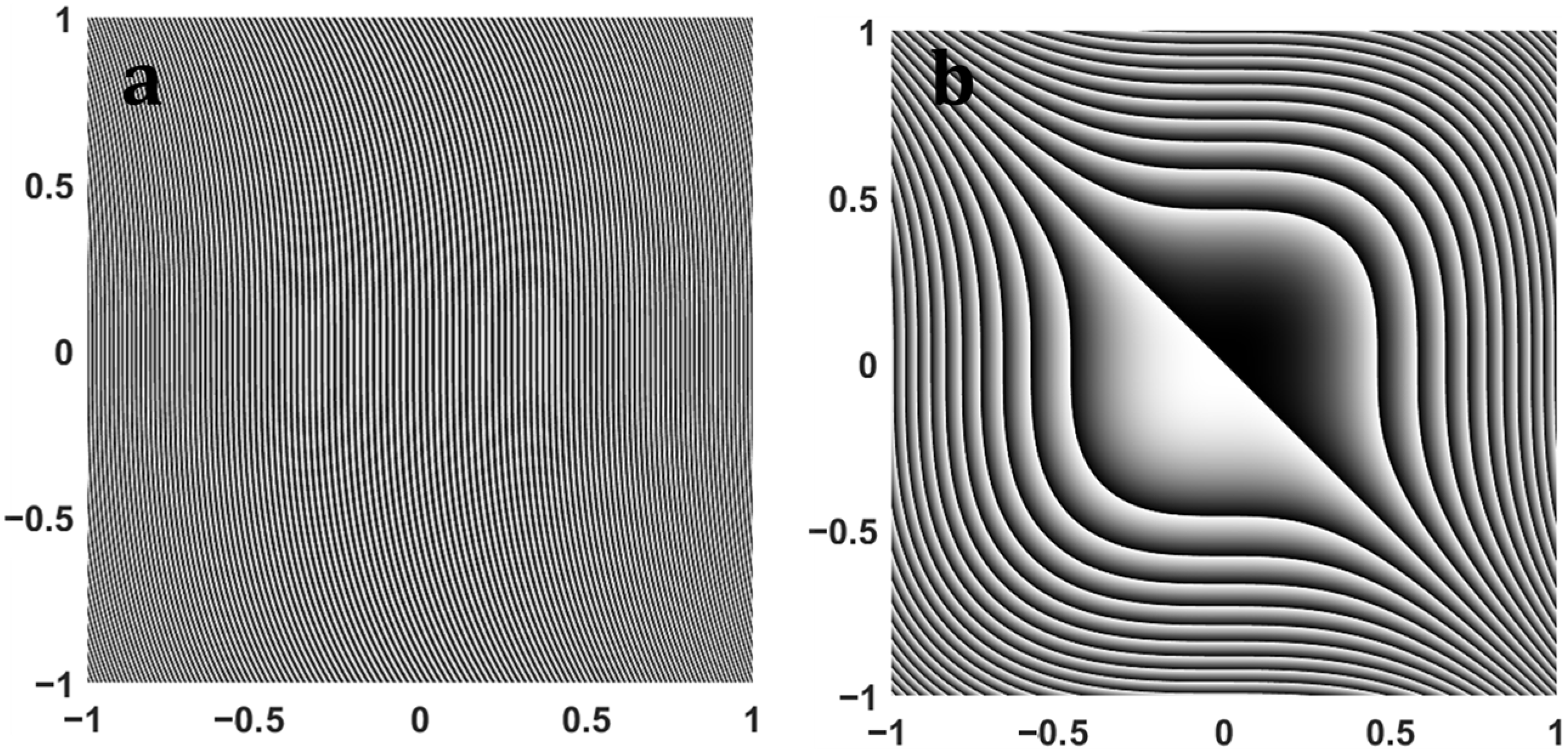
2. Theoretical Background

The two-dimensional Helmholtz equation under paraxial approximation is similar to the potential free Schrodinger equation [1,2,4]:
i ϕ ξ + 1 2 k 2 ϕ s x 2 + 1 2 k 2 ϕ s y 2 = 0 ,
where ϕ is the electric field envelope. ξ = z / z 0 represents the normalized longitudinal propagation distance, s x = x / x 0 and s y = y / y 0 are two dimensionless coordinates, where x 0 , y 0 and z 0 = k x 0 2 = k y 0 2 represent characteristic lengths. and k = 2 π n / λ 0 is wave vector. The evolution of the optical field of the two-dimensional finite-energy Airy beam can be described as follows:
ϕ ξ , s x , s y = A i s x ξ 2 2 + i a ξ · A i s y ξ 2 2 + i a ξ · e x p a s x + s y a ξ 2 i ξ 3 6 + i a 2 ξ + i s x + s y ξ ,
where a represents the attenuation coefficient ranging from 0 to 1 [41], and is designated as 0.07 in this work. A i ( s n ) denotes the Airy function. The expression for the field distribution of the aforementioned Airy beam at its initial position is as follows:
ϕ ξ = 0 , s x , s y = A i s x · Ai s y · exp a s x + s y .
By executing a Fourier transformation on the field distribution of the Airy beam at its initial position, we can obtain the Fourier spectrum of the Airy beam with finite energy:
ϕ ^ ξ = 0 , s x , s y = & exp 2 a 3 3 a u 2 + v 2 × e x p i a 2 u u 3 3 + a 2 v v 3 3 ,
where u ,   v are the corresponding frequency terms of s x   a n d   s y after Fourier transform. A Gaussian spectrum containing a cubic phase can be observed from the above equation, i.e., a finite energy pulsed Airy beam can be obtained by spatially modulating a Gaussian beam with a cubic phase, followed by a 2-D Fourier transform. In this work, the superposition of the cubic phase in space is accomplished using a transmissive two-dimensional binary phase diffractive optical element (DOE), whose phase profile function can be expressed as [2,42]:
φ = cos 2 π x p e r i o d + 64 x 3 + 64 y 3 ,
where the p e r i o d is 20 µm, defined by the quantity of lines per unit width of the grating element along the x -axis [43]. The binary phase profile diagram ( 2 × 2 mm) etched on the DOE is shown in Figure 1a, while Figure 1b illustrates the cubic phase diagram ( 2 × 2 mm) superimposed on the pulsed Gaussian beam.

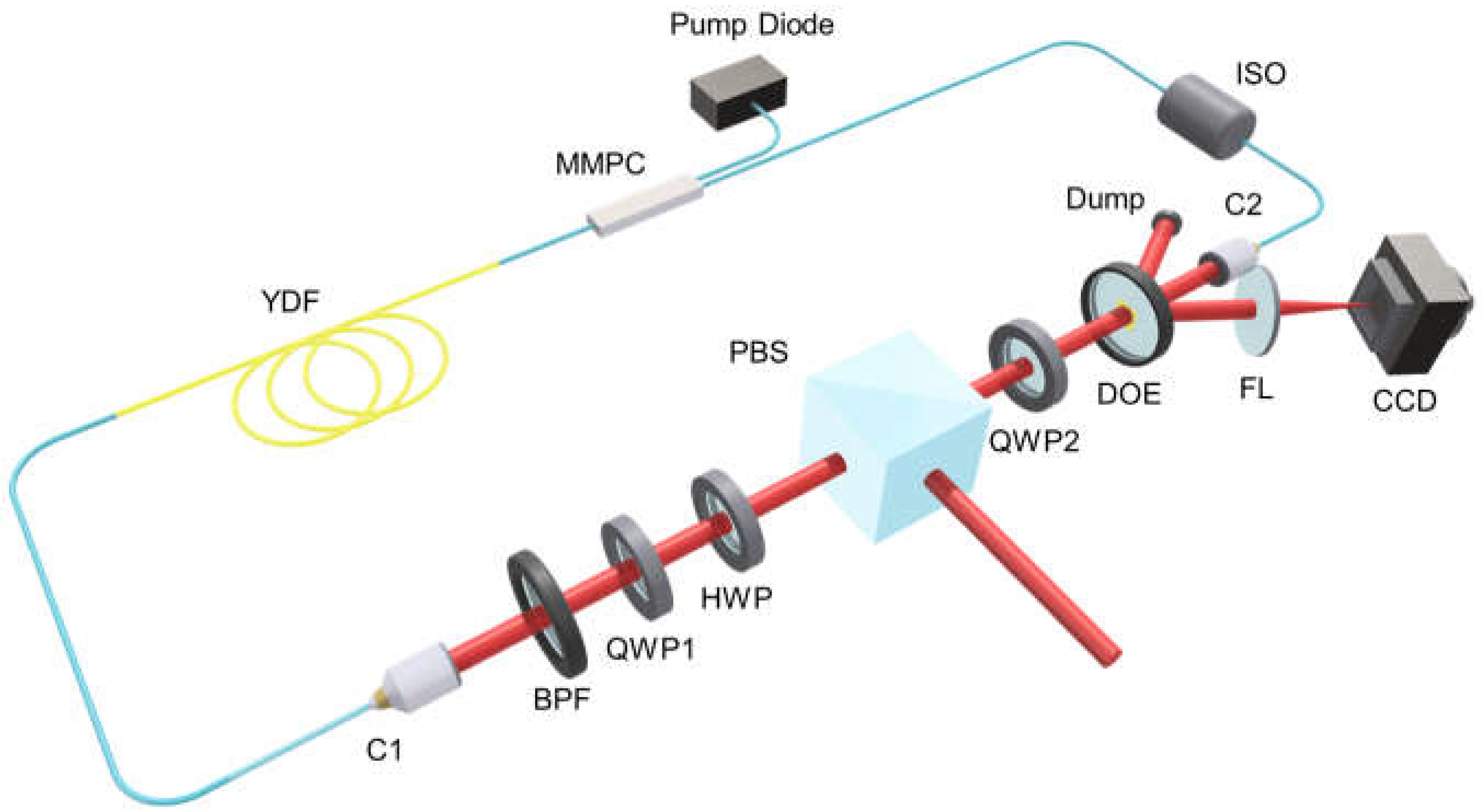
3. Experimental Setup

The schematic of the experimental setup for the pulsed Airy beam fiber laser is shown in Figure 2, which is a unidirectional ring laser cavity which can achieve mode-locking by means of nonlinear polarization rotation (NPR). NPR is a commonly used technique of passive mode-locking in ultrafast fiber lasers [44,45], which is based on the self-phase modulation and cross-phase modulation of the pulses in the fiber laser cavity, and the cumulative nonlinear phase shifts in the pulses of different intensity are different. Therefore, the two orthogonal components of the elliptically polarized light will have different degrees of polarization rotation. The combination of a polarization dependent isolator and a polarization controller is equivalent to a saturable absorber, through which the pulses are continuously narrowed by the fast saturable absorption mechanism. The laser cavity is pumped by a semiconductor laser with a maximum output power of 10 W and a central wavelength of 974 nm. The energy is coupled into the laser cavity through a Multimode Pump and Signal Combiner (MMPC) to pump a 3 m-long Ytterbium-doped gain fiber (LMA-YDF-10/130-M, NA = 0.075, Nufern, 3, 4/F, Building D, T4, Tian’an Cyber Park, Huang Ge Road, Center City Longgang District, Shenzhen 518172, China). The laser beam emerges from the optical fiber collimator 1 (C1), and first passes through an interference band-pass filter (BPF) with a central wavelength of 1064 nm and the full width at half maximum (FWHM) of 10 nm, (GCC-201039, peak transmittance = 85%, Daheng Optics, #A9, Shangdi Xinxi, Haidian District, Beijing 100085, China). The BPF is employed to ensure that the central wavelength of mode locking is approximately around 1064 nm and to filter out the excessive pump light. Subsequently, the laser beam successively passes through the NPR structure, which consists of a quarter wave plate (QWP 1), a half wave plate (HWP), a polarization beam splitter (PBS), and another quarter wave plate (QWP 2). This part serves as a saturable absorber. A diffractive optical element (DOE), in the form of a binary grating (PE-203-I-Y-A, fused silica, transmittance: ~100%, Holo/Or), is used for the cubic phase modulation of the Gaussian beam for the generation of pulsed Airy beam. The DOE has a central operation wavelength of 1064 nm, a diameter of 25.4 mm and a thickness of 3 mm. The element can modulate a Gaussian pulse with a maximum beam diameter of 2 mm. At 1064 nm, the DOE has an 0th order diffraction efficiency of ~59.2%. This part of the energy is then returned to the laser cavity through the collimator 2 (C2), while the corresponding cubic phase modulated Gaussian beam (~2 × 20.4% of the pulse), in the form of first order of the diffracted beams, will output the laser cavity at a separation angle of ~3.05 degree. Whereafter simply by using a Fourier lens (FL) outside the cavity with a focal distance of f = 100 mm, the Fourier transform of the modulated pulse, diffracted from the laser cavity, will eventually generate the pulsed Airy beam at the focal plane of the Fourier lens. An isolator (ISO) is used to ensure that the light propagates unidirectionally in the ring cavity. One of the first-order diffraction beams, which has not been selected for further experiment and has no practical application, is dumped.

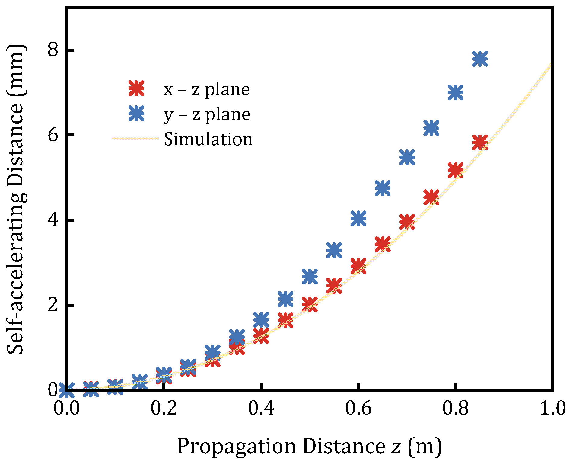
4. Results and Discussion

The generated pulsed Airy beam is characterized by a spectrum analyzer (OSA, YOKOGAWA, AQ6370C), a 1 GHz oscilloscope (RIGOL, DS6104), a 5 GHz photodetector (THORLABS, DET08CFC/M), an autocorrelator (FEMTOCHROME, FR-103XL), and a radio frequency (RF) spectrum analyzer (RIGOL, DSA815), and a CCD (LIGHTING, LT-2600-VIS-NIR).
Stable mode locking with an average output power of 159.1 mW from the PBS can be obtained by appropriately rotating the wave plates when the pump power exceeds 1.7 W, while the pulsed Airy beam exhibits an output power of 26.6 mW on a single side. The pulsed Airy beam has a spectrum centered at 1064.46 nm with a 3 dB bandwidth of ~6.56 nm, as shown in Figure 3a. Figure 3b shows the output pulsed Airy beam train with a pulse interval of 49.33 ns. One possible cause of the amplitude fluctuation of the pulses in Figure 3b is probably due to environmental disturbance. Figure 3c exhibits the corresponding radio frequency (RF) spectrum, with a fundamental repetition rate of 20.27 MHz and a signal-to-noise ratio (SNR) of 55.13 dB. The RF spectrum over a 400 MHz region is depicted in the accompanying graph, demonstrating that the mode-locking remains in a stable and undisturbed situation. The autocorrelation trace of the mode-locked pulsed Airy beam and its hyperbolic secant curve (red line in Figure 3d) show that the pulse duration is about 56.7 ps.
One characteristic of the Airy beam is self-acceleration (self-bending). In order to investigate the self-acceleration of the pulsed Airy beam we obtained, a CCD is placed in the direction of the propagation of the first order diffracted beam, which is generated by the Gaussian pulse passing through the DOE. The Fourier lens is placed between the DOE and the CCD, and the distance from the Fourier lens to the CCD is the focal length of the Fourier lens. The 2-D intensity profile at different distance from the Fourier plane can be recorded by moving the CCD along the beam propagation, as shown in Figure 4 schematically. Figure 4e–h records the transverse beam profiles ( 12 × 12 mm) of the 2-D pulsed Airy beam at distances of z = 0 m, 0.25 m, 0.5 m and 0.75 m from the focal plane of the Fourier lens, respectively. The red dotted lines illustrate the propagation trajectory of the main lobe of the pulsed Airy beam, which exhibits an obvious self-accelerating behavior. Figure 4a–d depict the simulation diagrams ( 12 × 12 mm) associated with the propagation distances. Figure 4i illustrates the propagation trajectory of a two-dimensional pulsed Airy beam after passing through the Fourier plane, accompanied by a schematic representation of the beam profile. The red line represents the actual propagation trajectory of the 2-D pulsed Airy beam, while the yellow straight line denotes a reference direction along the z-axis. As the propagation distance z ( z = 0, 0.25, 0.5 and 0.75 m) increases, the beam’s main lobe exhibits an obvious lateral displacement in both the x and y directions, indicating of self-acceleration, a unique characteristic of Airy beams. Meanwhile, the beam profiles of pulsed Airy beams remain stable and retain a distinct Airy function form over significant propagation distances, indicating their relative stability.
In order to demonstrate the lateral displacement of the main lobe of the pulsed Airy beam, Figure 5 presents the shifts in the main lobe in the x z and y z planes over a propagation distance z ranging from 0 to 0.85 m. The yellow lines represent the simulation of the transverse displacement varying with the propagation distance z . The red and blue asterisks denote the actual transverse displacements along the x -axis and the y -axis, respectively, with the propagation distance z increases, exhibiting obvious self-accelerating behavior on both axes, indicating that a good quality pulsed Airy beam is generated at this time. The self-accelerating motion trajectories obtained from experimental measurements display minor discrepancies relative to those from theoretical simulations. This may be considered as the experimental deviation originating from the pulsed Airy beam not traversing precisely through the center of the Fourier lens.

5. Conclusions

We have obtained the pulsed Airy beam from a Yb-doped fiber laser, by introducing a diffraction element DOE in the mode-locked laser cavity, which provides the cubic phase modulation required to obtain the Airy beam. Compared to the approach of integrating the DOE outside the cavity, our design effectively guides the high-energy zero-order diffraction pulse back into the cavity, thereby reducing the potential risk of damage to external equipment. This makes it particularly suitable for applications in fields such as aerospace, where there is a strong demand for lightweight and miniaturized devices. Moreover, by eliminating the need for external spatial light modulators (SLM) and their associated computers, stable power supplies, and polarization control components, our system becomes more compact, cost-effective, and easier to operate. The current optical diffraction components still necessitate the placement of a Fourier lens outside the cavity to transfer the lens phase. There is optimism that both the lens phase information and cubic phase distributions can be etched onto the DOE [35,46] to accomplish the complete direct generation of pulsed Airy beams within the cavity. However, compared with continuous-wave lasers [5] and ultrafast optical parametric oscillators [23,24] that use the same principle, mode-locked fiber lasers can generate Airy beam in pulse form and maintain a compact setup, due to the advantage of directly generating pulsed Airy beams in the cavity without additional modulation outside the laser cavity. In addition, our method can also be used to generate laser pulses with other beam profiles, such as pulsed vortex beams [47], pulsed Bessel beams [48], etc.

Author Contributions

Writing—original draft preparation, S.G.; investigation, F.Z., C.Y. and Y.L.; supervision, X.Z. All authors have read and agreed to the published version of the manuscript.

Funding

This research was funded by Shenzhen Fundamental Research Program (Grant JCYJ20210324115608024) and China National Research Program (Grant 2022YFB3806900).

Data Availability Statement

The data that support the findings of this study are available from the corresponding author upon reasonable request.

Conflicts of Interest

Author Fan Zhang is employed by the company Shenzhen Gongda Laser Co., Ltd. The remaining authors declare that the research was conducted in the absence of any commercial or financial relationships that could be construed as a potential conflict of interest.

References

  1. Siviloglou, G.A.; Christodoulides, D.N. Accelerating finite energy airy beams. Opt. Lett. 2007, 32, 979–981. [Google Scholar] [CrossRef] [PubMed]
  2. Porat, G.; Dolev, I.; Barlev, O.; Arie, A. Airy beam laser. Opt. Lett. 2011, 36, 4119–4121. [Google Scholar] [CrossRef] [PubMed]
  3. Minovich, A.E.; Klein, A.E.; Neshev, D.N.; Pertsch, T.; Kivshar, Y.S.; Christodoulides, D.N. Airy plasmons: Non-diffracting optical surface waves. Laser Photonics Rev. 2013, 8, 221–232. [Google Scholar] [CrossRef]
  4. Siviloglou, G.A.; Broky, J.; Dogariu, A.; Christodoulides, D.N. Observation of accelerating airy beams. Phys. Rev. Lett. 2007, 99, 213901. [Google Scholar] [CrossRef]
  5. Wong, C.W. Nonspreading wave packets. Am. J. Phys. 1996, 64, 792–799. [Google Scholar] [CrossRef]
  6. Durnin, J.; Miceli, J.J.; Eberly, J.H. Diffraction-free beams. Phys. Rev. Lett. 1987, 58, 1499–1501. [Google Scholar] [CrossRef] [PubMed]
  7. Kotlyar, V.V.; Kovalev, A.A. Airy beam with a hyperbolic trajectory. Opt. Commun. 2014, 313, 290–293. [Google Scholar] [CrossRef]
  8. Efremidis, N.K.; Chen, Z.G.; Segev, M.; Christodoulides, D.N. Airy beams and accelerating waves: An overview of recent advances. Optica 2019, 6, 686–701. [Google Scholar] [CrossRef]
  9. Zhang, P.; Prakash, J.; Zhang, Z.; Mills, M.S.; Efremidis, N.K.; Christodoulides, D.N.; Chen, Z. Trapping and guiding microparticles with morphing autofocusing airy beams. Opt. Lett. 2011, 36, 2883–2885. [Google Scholar] [CrossRef] [PubMed]
  10. Baumgartl, J.; Mazilu, M.; Dholakia, K. Optically mediated particle clearing using airy wavepackets. Nat. Photonics 2008, 2, 675–678. [Google Scholar] [CrossRef]
  11. Christodoulides, D.N. Riding along an airy beam. Nat. Photonics 2008, 2, 652–653. [Google Scholar] [CrossRef]
  12. Zhang, P.; Zhang, Z.; Prakash, J.; Huang, S.; Chen, Z. Trapping and transporting aerosols with a single optical bottle beam generated by moiré techniques. Opt. Lett. 2011, 36, 1491–1493. [Google Scholar] [CrossRef] [PubMed]
  13. Qu, Z.; Wang, K.; Feng, C.; Wu, T.; Zhang, Y.; Zhao, X.; Wang, J.-L. Optofluidic sorting of microparticles using airy beams. Int. J. Optomechatronics 2024, 18, 2375538. [Google Scholar] [CrossRef]
  14. Vettenburg, T.; Dalgarno, H.I.C.; Nylk, J.; Coll-Lladó, C.; Ferrier, D.E.K.; Čižmár, T.; Gunn-Moore, F.J.; Dholakia, K. Light-sheet microscopy using an airy beam. Nat. Methods 2014, 11, 541–544. [Google Scholar] [CrossRef] [PubMed]
  15. Stegmeyer, R.I.; Stasch, M.; Olesker, D.; Taylor, J.M.; Mitchell, T.J.; Hosny, N.A.; Kirschnick, N.; Spickermann, G.; Vestweber, D.; Volkery, S. Intravital microscopy with an airy beam light sheet microscope improves temporal resolution and reduces surgical trauma. Microsc. Microanal. 2024, 30, 925–943. [Google Scholar] [CrossRef]
  16. Chen, L.; Gao, B.; Li, X.; Chan, C.T.; Wang, J.; Ye, L.; Wang, L.-G. Optimizing airy needle-like beams for long-range axial manipulation and super-resolution imaging. ACS Photonics 2024, 11, 3610–3620. [Google Scholar] [CrossRef]
  17. Abdollahpour, D.; Suntsov, S.; Papazoglou, D.G.; Tzortzakis, S. Spatiotemporal airy light bullets in the linear and nonlinear regimes. Phys. Rev. Lett. 2010, 105, 253901. [Google Scholar] [CrossRef] [PubMed]
  18. Chong, A.; Renninger, W.H.; Christodoulides, D.N.; Wise, F.W. Airy–bessel wave packets as versatile linear light bullets. Nat. Photonics 2010, 4, 103–106. [Google Scholar] [CrossRef]
  19. Mathis, A.; Courvoisier, F.; Froehly, L.; Furfaro, L.; Jacquot, M.; Lacourt, P.A.; Dudley, J.M. Micromachining along a curve: Femtosecond laser micromachining of curved profiles in diamond and silicon using accelerating beams. Appl. Phys. Lett. 2012, 101, 071110. [Google Scholar] [CrossRef]
  20. Götte, N.; Winkler, T.; Meinl, T.; Kusserow, T.; Zielinski, B.; Sarpe, C.; Senftleben, A.; Hillmer, H.; Baumert, T. Temporal airy pulses for controlled high aspect ratio nanomachining of dielectrics. Optica 2016, 3, 389–395. [Google Scholar] [CrossRef]
  21. Muhammad, I.; Jiang, R.; Lin, Y.; Zheng, X.; Dehdashti, B. Airy beams on two dimensional materials. Opt. Commun. 2018, 414, 40–44. [Google Scholar]
  22. Polynkin, P.; Kolesik, M.; Moloney, J.V.; Siviloglou, G.A.; Christodoulides, D.N. Curved plasma channel generation using ultraintense airy beams. Science 2009, 324, 229–232. [Google Scholar] [CrossRef]
  23. Li, L.; Li, T.; Wang, S.M.; Zhang, C.; Zhu, S.N. Plasmonic airy beam generated by in-plane diffraction. Phys. Rev. Lett. 2011, 107, 126804. [Google Scholar] [CrossRef] [PubMed]
  24. Liu, W.; Neshev, D.N.; Shadrivov, I.V.; Miroshnichenko, A.E.; Kivshar, Y.S. Plasmonic airy beam manipulation in linear optical potentials. Opt. Lett. 2011, 36, 1164–1166. [Google Scholar] [CrossRef]
  25. Zhang, P.; Wang, S.; Liu, Y.; Yin, X.; Lu, C.; Chen, Z.; Zhang, X. Plasmonic airy beams with dynamically controlled trajectories. Opt. Lett. 2011, 36, 3191–3193. [Google Scholar] [CrossRef]
  26. Gao, X.; Han, Y.; Wang, J.; Xu, S. Evolution of airy beams in turbulence plasma sheath. Photonics 2024, 11, 102. [Google Scholar] [CrossRef]
  27. Gao, C.; Wen, B.; Deng, Y.; Fan, Y.; Wei, J.; Chen, D. Generation and manipulation of airy breathing solitons in an inhomogeneous medium with periodic potential. Photonics 2023, 10, 486. [Google Scholar] [CrossRef]
  28. Courvoisier, S.; Götte, N.; Zielinski, B.; Winkler, T.; Sarpe, C.; Senftleben, A.; Bonacina, L.; Wolf, J.P.; Baumert, T. Temporal airy pulses control cell poration. APL Photonics 2016, 1, 046102. [Google Scholar] [CrossRef]
  29. Hu, Z.; Yang, Y.; Yang, L.; Gong, Y.; Chukwu, C.; Ye, D.; Yue, Y.; Yuan, J.; Kravitz, A.V.; Chen, H. Airy-beam holographic sonogenetics for advancing neuromodulation precision and flexibility. Proc. Natl. Acad. Sci. USA 2024, 121, e2402200121. [Google Scholar] [CrossRef] [PubMed]
  30. Zhang, Q.; Liu, Z.; Wang, X. Generation of an airy-related beam from the sinusoidal dark hollow beam. Optik 2022, 251, 168477. [Google Scholar] [CrossRef]
  31. Voloch-Bloch, N.; Lereah, Y.; Lilach, Y.; Gover, A.; Arie, A. Generation of electron airy beams. Nature 2013, 494, 331–335. [Google Scholar] [CrossRef] [PubMed]
  32. Hu, J.; Guo, Z.; Shi, J.; Jiang, X.; Chen, Q.; Chen, H.; He, Z.; Song, Q.; Xiao, S.; Yu, S.; et al. A metasurface-based full-color circular auto-focusing airy beam transmitter for stable high-speed underwater wireless optical communications. Nat. Commun. 2024, 15, 2944. [Google Scholar] [CrossRef]
  33. Ellenbogen, T.; Voloch-Bloch, N.; Ganany-Padowicz, A.; Arie, A. Nonlinear generation and manipulation of airy beams. Nat. Photonics 2009, 3, 395–398. [Google Scholar] [CrossRef]
  34. Khonina, S.N. Specular and vortical airy beams. Opt. Commun. 2011, 284, 4263–4271. [Google Scholar] [CrossRef]
  35. Latychevskaia, T.; Schachtler, D.; Fink, H.W. Creating airy beams employing a transmissive spatial light modulator. Appl. Opt. 2016, 55, 6095–6101. [Google Scholar] [CrossRef]
  36. Zhang, P.; Hu, Y.; Cannan, D.; Salandrino, A.; Li, T.; Morandotti, R.; Zhang, X.; Chen, Z. Generation of linear and nonlinear nonparaxial accelerating beams. Opt. Lett. 2012, 37, 2820. [Google Scholar] [CrossRef] [PubMed]
  37. Aadhi, A.; Sharma, V.; Chaitanya, N.A.; Samanta, G.K. Multi-gigahertz, femtosecond airy beam optical parametric oscillator pumped at 78 mhz. Sci. Rep. 2017, 7, 43913. [Google Scholar] [CrossRef]
  38. Apurv Chaitanya, N.; Kumar, S.C.; Aadhi, A.; Samanta, G.K.; Ebrahim-Zadeh, M. Ultrafast airy beam optical parametric oscillator. Sci. Rep. 2016, 6, 30701. [Google Scholar] [CrossRef] [PubMed]
  39. Aadhi, A.; Chaitanya, N.A.; Jabir, M.V.; Vaity, P.; Singh, R.P.; Samanta, G.K. Airy beam optical parametric oscillator. Sci. Rep. 2016, 6, 25245. [Google Scholar] [CrossRef] [PubMed]
  40. Valdmann, A.; Piksarv, P.; Valtna-Lukner, H.; Saari, P. Realization of laterally nondispersing ultrabroadband airy pulses. Opt. Lett. 2014, 39, 1877–1880. [Google Scholar] [CrossRef] [PubMed]
  41. Vallée, O.; Soares, M. Airy Functions and Applications to Physics; Imperial College Press: London, UK, 2004. [Google Scholar]
  42. Lee, W.H. Binary computer-generated holograms. Appl. Opt. 1979, 18, 3661–3669. [Google Scholar] [CrossRef]
  43. Morris, J.E.; Mazilu, M.; Baumgartl, J.; Čižmár, T.; Dholakia, K. Propagation characteristics of airy beams: Dependence upon spatial coherence and wavelength. Opt. Express 2009, 17, 13236–13245. [Google Scholar] [CrossRef]
  44. Lin, Y.; Huang, Z.; Huang, Q.; Dai, L.; Song, Q.; Yan, Z.; Mou, C.; Zhou, K.; Zhang, L. Pump-controlled wavelength switchable dissipative soliton mode-locked yb-doped fiber laser using a 45° tilted fiber grating. Optik 2020, 222, 165383. [Google Scholar] [CrossRef]
  45. Oktem, B.; Ülgüdür, C.; Ilday, F.Ö. Soliton–similariton fibre laser. Nat. Photonics 2010, 4, 307–311. [Google Scholar] [CrossRef]
  46. Davis, J.A.; Mitry, M.J.; Bandres, M.A.; Ruiz, I.; McAuley, K.P.; Cottrell, D.M. Generation of accelerating airy and accelerating parabolic beams using phase-only patterns. Appl. Opt. 2009, 48, 3170–3176. [Google Scholar] [CrossRef]
  47. Wang, X.; Nie, Z.; Liang, Y.; Wang, J.; Li, T.; Jia, B. Recent advances on optical vortex generation. Nanophotonics 2018, 7, 1533–1556. [Google Scholar] [CrossRef]
  48. Wang, J.; Liu, J.; Li, S.; Zhao, Y.; Du, J.; Zhu, L. Orbital angular momentum and beyond in free-space optical communications. Nanophotonics 2022, 11, 645–680. [Google Scholar] [CrossRef] [PubMed]
Figure 1. (a) The binary phase profile diagram etched on the DOE. (b) The cubic phase diagram superimposed on the pulsed Gaussian beam.
Photonics 12 00009 g001
Figure 2. The schematic of the experimental setup for the pulsed Airy beam fiber laser.
Photonics 12 00009 g002
Figure 3. Measurement results of the laser output under the pump power of 1.7 W. (a) Output optical spectrum. (b) Pulse trains. (c) RF spectrum. (d) Autocorrelation trace and the hyperbolic secant curve.
Photonics 12 00009 g003
Figure 4. Experimental and simulation results for the propagation of pulsed Airy beams. Intensity profiles of the 2-D Pulsed Airy beam at (e) z = 0 m, (f) z = 0.25 m, (g) z = 0.5 m, (h) z = 0.75 m from the focal plane of the Fourier lens along the propagation direction, along with the simulation diagrams corresponding to the propagation distances at (a) z = 0 m, (b) z = 0.25 m, (c) z = 0.5 m, (d) z = 0.75 m. (i) the schematic diagram of the propagation trajectory of 2-D pulsed Airy beam, where the red line representing the actual propagation trajectory of the 2-D pulsed Airy beam and the yellow straight line indicating the reference direction along the z -axis.
Photonics 12 00009 g004
Figure 5. The displacements of the main lobe in the x z (red asterisks) plane, y z (blue asterisks) plane with propagation distance z from 0 to 0.85 m and the simulation results (yellow lines) vary with propagation distance z from 0 to 1 m.
Photonics 12 00009 g005
Disclaimer/Publisher’s Note: The statements, opinions and data contained in all publications are solely those of the individual author(s) and contributor(s) and not of MDPI and/or the editor(s). MDPI and/or the editor(s) disclaim responsibility for any injury to people or property resulting from any ideas, methods, instructions or products referred to in the content.

