Abstract
The high-order microring filter has been proposed for a larger free spectral range (FSR) compared with the single microring filter; therefore, it has great potential to be used in wavelength division multiplexing (WDM) systems. In this article, we have designed and fabricated a second-order microring filter made up of two rings connected in series with two Ti thermal heaters deposited above them. The large FSR of 56.8 nm is obtained by decreasing the difference of the radii between the two series rings, achieving similar FSRs to that of higher-order filters but with a simpler and more compact design. The average electrical tuning efficiencies of the two heaters are 0.186 nm/mW and 0.207 nm/mW, and the center wavelength of the filter can be tuned over the entire FSR with an applied electrical power of less than 40 mW.
1. Introduction
The rapid development of big data and the internet has put forward higher requirements and greater challenges for the speed and capacity of optical communication and interconnect systems. The second next generation passive optical network (NG-PON2) was proposed by the International Telecommunication Union-Telecommunication (ITU-T) to respond to the growing market demand [1,2]. In a passive optical network (PON), optical tunable filters are necessary for subscriber terminals to extract individual wavelength channels from wavelength-division multiplexing (WDM) devices. The expanded communication spectrum for such a WDM system requires optical tunable filters with a larger free spectral range (FSR) and a larger wavelength tunable range. Furthermore, low insertion loss (IL), appropriate bandwidth, high side mode suppression ratio (SMSR) and good filter shape are also extremely important for filters in optical communication.
Silicon-based optical filters, which have the characteristics of compact structure, low loss and Complementary-Metal-Oxide-Semiconductor (CMOS) process compatibility, have become a research hotspot [3]. Silicon-based optical tunable filters can be based on different structures, such as Mach–Zehnder interferometers (MZIs) [4,5], microring resonators (MRRs) [6,7] and Bragg gratings.
Among various types of optical filters, the MRR is an outstanding filter for its simple structure and compact footprint. For MRR filters, it is often very important to increase the free spectral range (FSR) so that they can accommodate more wavelength channels, and thereby increase the total bandwidth of the communication system. The FSR is inversely proportional to the microring radius; the smaller the radius is, the larger the FSR is. However, too small a radius can lead to excessive waveguide losses. For example, a 2.5 μm-radius-microring filter yields only an FSR of 35 nm [8]. A good scheme to expand the FSR of a filter is to cascade two rings with different radii to realize the Vernier effect. This scheme has been proposed and widely adopted for sensor applications to greatly enhance their sensitivities [9,10]. Zhou et al. designed a filter with a cascaded dual-ring structure by connecting the drop ends of two rings, which can be continuously tuned in the range of 1520–1600 nm [11]. However, the cascaded-ring filter yields a spectrum with a sharp top, which is undesirable for optical communications as it cannot withstand the effects of wavelength drifts caused by environmental changes, while the filter made up of rings coupled in series yields a spectrum with a flat top [12,13,14,15,16,17,18,19,20]. By connecting the same rings in series, the flat-top filter response can be achieved, and the rising and falling edge of the filter is steeper than that of the single-ring filter, but the FSR cannot be increased [15]. Jayatilleka et al. used in-resonator photoconductive heaters to both sense and control the intra-cavity light intensity of microring resonators, and tuned the second-order filter across the FSR of 35.8 nm [16]. Carrier-injected waveguides make the thermal tuning more sensitive and more accurate, but the excessive electrical powers applied lead to an increase in the loss of doped waveguides, which are not favorable for optical communication. Higher-order microring filters are designed and fabricated for a larger FSR [17,18], and Morichetti et al. designed a fourth-order filter with an FSR over 90 nm which requires multiple electrodes to be tuned separately to achieve the shift of the filter spectrum, which leads to complex tuning algorithms [18].
To achieve reconfigurability in both central wavelength and bandwidth by thermal tuning, several schemes have been proposed. The notch filters were proposed by connecting the through ends of two rings, and the electrical powers are applied to each ring to realize the tuning of bandwidth and center wavelength, respectively [21,22]. However, the trapped spectrum should be used with a phase modulator to achieve a bandpass filter, which is not conducive to integration. Liu et al. proposed a fourth-order microring filter, where the center frequency tunable range of 5.20 to 35.80 GHz can be achieved by thermally tuning the resonant frequencies of the four rings separately, and a bandwidth tunable range of 0.70 to 2 GHz can be achieved by designing the coupling region as an MZI structure and placing thermal electrodes above the two arms of the MZI for thermal tuning [23]. Thermal crosstalk due to overheating of the chip is an issue that needs to be addressed in this design.
The filter we proposed has a fixed bandwidth, which is set for the specific requirements of optical communication, so there is no need for additional design for the reconfigurability in bandwidth. Compared to the designs reported in previous works referred to in [21,22], our filter amplifies the FSR through the Vernier Effect, and compared with the work referred to in [23], our work simplifies the structure and is conducive to the development of integration. Above all, microring filters with a large FSR, flat top, simple fabrication process and tuning algorithm are highly desirable for practical applications.
In this paper, we propose and fabricate a second-order microring filter with a large FSR of 56.3 nm. The large FSR is obtained by decreasing the difference of the radii between the two series rings. This design is simpler and more compact than higher-order rings for similar FSRs. The key to obtaining the performance of a large FSR and a high SMSR simultaneously is adjusting the coupling coefficient between the ring and the input/output waveguide, and the flat top is ensured by corresponding adjustment of the coupling coefficient between the two rings. Ti thermal heaters are deposited above the rings to respectively adjust the position of the resonant peaks of two rings to form the spectra with a flat top. In view of the average electrical tuning efficiencies of 0.186 nm/mW and 0.207 nm/mW for the two heaters, the center wavelength of the filter can be tuned over the entire FSR with an applied electrical power of less than 40 mW.
2. Theoretical Analysis
As shown in Figure 1, the second-order microring filters consist of two rings coupled in series, which can be thermally tuned by heating electrodes. Its spectrum is calculated using the transmission matrix method. In the coupling region, according to the coupling mode equation, the amplitude of the light field can be expressed as
where is the coupling coefficient between the ring and the input/output waveguide and is the transfer coefficient between the ring and the input/output waveguide.
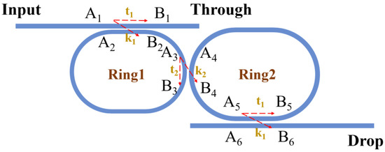
Figure 1.
Structure diagram of second-order microring filters.
Depending on the transmission of light inside the ring resonator, the amplitude of the light field can be expressed as
where is the propagation constant, is the radius of ‘Ring1’ and is the attenuation coefficient of light propagation within the rings.
By the same token, the output amplitude of the filter can be expressed as
where is the coupling coefficient between the two rings, is the transfer coefficient between the two rings and is the radii of ‘Ring2’.
Cause , the light intensity at the drop port can be expressed in dB as
To meet the optical communication requirements, the FSR of the second-order filter is set to around 60 nm. The least common multiple of the FSRs of the two rings are set as 7 nm and 8 nm. The radii can be calculated as
where is group refractive index and , is effective refractive index. According to the calculations, the radii of the two rings are set to 10.5 μm and 12 μm.
To achieve a flat top, it is necessary to ensure that the output is maximum at the center wavelength and that both rings are resonant at the center wavelength. That is, , , , where and are the resonance order numbers of the two rings. Assuming the device is lossless, that is , and substituting the above values into Equation (1), the relationship between and can be expressed as
Figure 2 shows the simulated spectra of the filters for different values of coupling coefficients. As shown in Figure 2a, the larger value of brings wider bandwidth of the main peak, but less sharp rising and falling edges, and a smaller secondary peak suppression ratio. Conversely, a smaller value of results in a box-like filter spectrum and a larger suppression ratio, which is more conducive to communication applications. However, too small a value of , which results in large insertion loss (IL) and small full-width at-half-maximum (FWHM), limits the applications of filters. Considering the need of the communication applications for SMSR and FWHM, is set as 0.35. The value of needs to be adjusted slightly to obtain the filtering spectrum with a flat top since the device loss is neglected in Equation (3). The waveguide transmission loss of the ring was 8 dB/cm measured in the experiment and we set as in the simulation of the light intensity at the drop port. Too large a value of will result in ripples at the top, while too small a value of brings Lorentz spectra with narrow FWHM. As a result, we chose as 0.08.
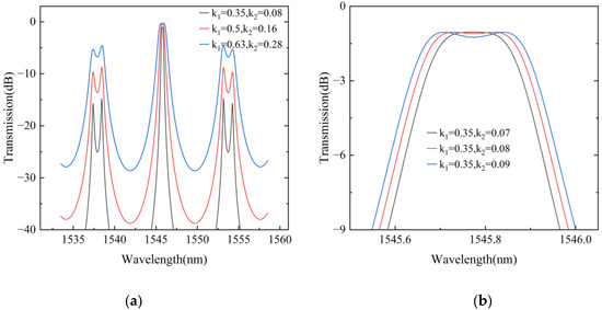
Figure 2.
Simulation of coupling coefficients: (a) the spectra for different values, (b) the spectra for different values.
According to the above design parameters, the simulated spectra are shown in Figure 3. The FSR of the second-order microring filter is 56.8 nm, with an SMSR of 12.7 dB, an IL of 1.2 dB and an FWHM of 0.3 nm.
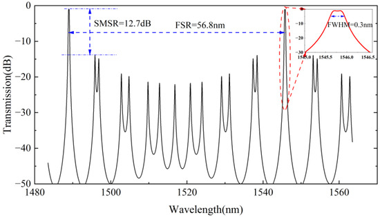
Figure 3.
Simulated spectra of second-order microring filters.
3. Simulation of Filters
3.1. Simulation of the Coupling Coefficients
The waveguides of the filter are 450-nm-width silicon waveguides under the SOI material platform with silicon dioxide upper cladding. The coupling coefficient between two waveguides is related to the coupling length and the gap between the waveguides. As shown in Figure 4, the coupling coefficients versus gap and coupling length are simulated by the 2.5 D finite difference time domain (FDTD) for TE mode.
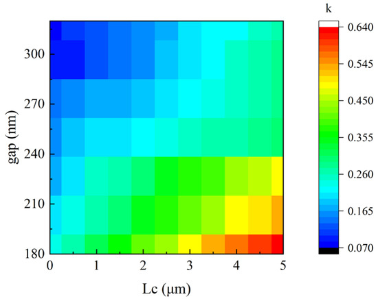
Figure 4.
The relationship between the gap, the coupling length and the coupling coefficients .
According to the previous section, is set as 0.35. The minimum value of the gap is 180 nm, which is limited by the process. Considering the small coupling coefficient of the TE mode, it is necessary to increase the coupling length to enhance the coupling efficiency. Therefore, the length of the coupling region between the ring and the waveguide is set to 2.2 μm with a gap of 180 nm, and the gap between the two rings is set as 300 nm based on the simulation results. Therefore, the rings are designed to be racetrack resonators.
3.2. Simulation of Thermal Tuning
Silicon-based photonic devices are often vulnerable to process error and are quite restricted in practical application. Especially for ring resonators, process errors may cause slight variations of the ring circumference, which may result in the initial resonant peaks of the two rings of the second-order microring filter not being perfectly aligned. It is necessary to add separate thermal heaters above rings to ensure that the resonance peaks of the two rings are aligned after applying appropriate electrical powers, so that a box-like filter spectrum can be obtained.
Heaters are placed above the waveguide, and electrical powers are applied to change the effective refractive index of the waveguide based on the thermo-optic (TO) effect [24,25]. The distributions of the thermal field around the waveguide caused by the electrical powers applied are simulated by the heat solver, and the effective refractive index and dispersion coefficient of the waveguide can be simulated by the Finite Difference Eigenmode (FDE) solver with the imported data of the thermal field distributions. In the simulation, the heat capacities and thermal conductivities for silicon, silicon dioxide and Ti metal are 148 W/mK and 711 J/kg·K, 1.38 W/mK and 709 J/kg·K, 21.9 W/mK and 520 J/kg·K, respectively.
The cross-section of the waveguide with the Ti heater above it and the thermal field distributions caused by applied electrical powers of 0.15 mW/um are shown in Figure 5. To minimize the effect of metal absorption on the transmission loss of the waveguide, the heater is placed above the waveguide at a distance of . Due to the relatively high TO coefficient of silicon (), thermal tuning with low electrical powers allows for a large change in the effective refractive index of the waveguide.
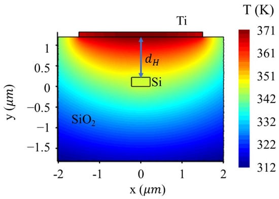
Figure 5.
The cross-section of the waveguide and the thermal field distributions.
3.3. Simulation of TO Effect on Effective Refractive Index and Coupling Coefficients
Both the effective refractive index and the coupling coefficient of the waveguide can be changed by thermo-optic (TO) effects. The effective refractive index of the waveguide is simulated by the FDE solver and the coupling coefficients are simulated by the 2.5 D FDTD. To simplify the simulation process, the changes in the effective refractive index and coupling coefficient are monitored by directly scanning the ambient temperature of the simulation region. The ambient temperature varies from 300 K to 400 K.
Figure 6a shows the simulated results of the effective refractive index varying with temperature, and when the temperature changes by 100 K, the effective refractive index changes by 0.02. As shown in Figure 6b, the spectrum of designed second-order microring filter shifts about 7 nm. Figure 7a shows the simulated results of the coupling coefficients ( and ) varying with temperature. When the temperature changes by 100 K, the coupling coefficient changes by 0.0145 and the coupling coefficient changes by 0.00598. The effects of changes in coupling coefficients ( and ) on the top of the spectra are shown in Figure 7b. A temperature change of 100 K brings a fluctuation of less than 0.1 dB on a flat top.
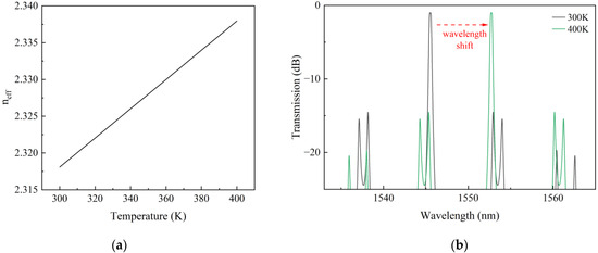
Figure 6.
(a) Simulation results of the effective refractive index () varying with temperature. (b) Simulation results of the spectra with different which is thermally tuned by 100 K.
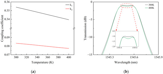
Figure 7.
(a) Simulation results of the coupling coefficients ( and ) varying with temperature. (b) Simulation results of the spectra with the different coupling coefficients ( and ) which is thermally tuned by 100 K.
4. Fabrication and Experimental Results
Filter chips were manufactured by using SOI wafers with a 220-nm-thick silicon core layer and a 2-μm-thick buried oxide layer. The pattern was generated by the stepper and transferred to the silicon core layer to form the silicon waveguides by Inductively Coupled Plasma (ICP) etching. Then, a 1.2-μm-thick silica up-cladding layer was deposited by Plasmonic Enhanced Chemical Vapor Deposition (PECVD), followed by a 100-nm-thick Ti layer deposited for the thermal heater. Figure 8 shows the microscope picture of a fabricated second-order microring filter.
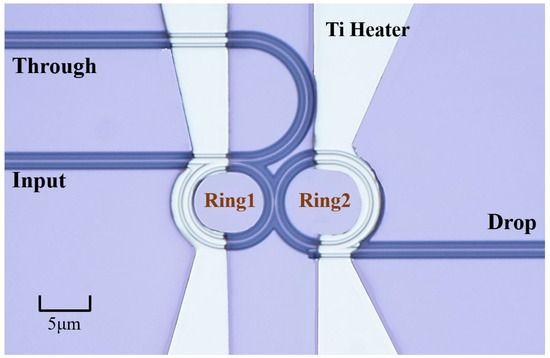
Figure 8.
The microscope picture of a fabricated second-order microring filter.
The spectrum of the filter was measured by the tunable laser source (Agilent 81606A, Agilent technology, Santa Clara, CA, USA) as the input light source and the power meter (Agilent 81634A, Agilent technology, Santa Clara, CA, USA) as the light detector. The tunable laser source has the resolution of 10 pm and the absolute wavelength accuracy of ±1.5 pm. The laser source and power meter were calibrated by a standard fixture before measurements were taken. The input optical power of 1 mW from the laser source was used during the detection. A Keithley 2602A source meter (Tektronix, Beaverton, OR, USA) was used to add suitable electrical powers to Ti electrodes for the desired filter spectra.
Figure 9 is the measured spectra of the second-order microring filter with electrical powers of 0.92 mW applied to ‘Ring2’. The FSR of the second-order filter is 56.8 nm, with an SMSR of 15.7 dB, an FWHM of 0.3 nm, a rising and falling edge of 98.5 dB/nm and an IL of 4.3 dB. The IL includes the transmission loss of 2.8 dB for 4-mm-long input/output waveguides. This can be significantly reduced by improving the waveguide fabrication quality and by reducing the input/output waveguide lengths. The measured filter spectra were not fully flat-topped, possibly affected by backscattered light, which was caused by waveguide defects and sidewall roughness [26,27]. In the microring resonators, backscattered light travels in the opposite direction to the original propagation direction and interferes with the original modes, forming two coupled modes and producing the phenomena of mode splitting and asymmetry of resonance peaks. A ripple of about 0.4 dB exists at the top of the filter, which can be reduced by improving the process and reducing the sidewall roughness.
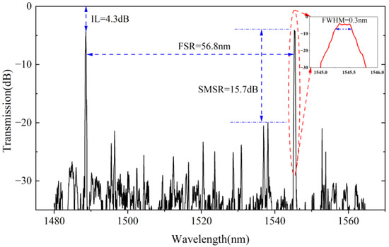
Figure 9.
Measured spectra of the second-order microring filters.
To tune the central wavelength of the filter, electrical currents are applied to the two heater electrodes simultaneously. The thermal effect generated by the electricity changes the effective refractive index of the waveguide, and then shifts the resonant wavelengths of the two rings synchronously due to the effective refractive index change. The center wavelength of the filter is located at the overlap of the resonant wavelengths of the two rings, and due to the Vernier Effect, tuning of either ring by one of its own FSRs can achieve tuning of the filter over the entire FSR, which greatly reduces the energy consumption for tuning the center wavelength of the filter across the FSR.
The filter spectra at different electrical powers are shown in Figure 10a. It is worth noting that the same color of the spectrum in the Figure 10a is simply a loop of the color bar, not an indication of the same spectrum. The values of applied electrical powers corresponding to the center wavelengths of the filter are shown in Figure 10b, and the average electrical tuning efficiencies for ‘Ring1’ and ‘Ring2’ are calculated as 0.186 nm/mW and 0.207 nm/mW. The center wavelength of the filter can be tuned over the entire FSR with an electrical power of less than 40 mW.
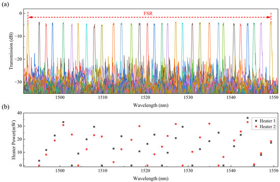
Figure 10.
Measured spectra of (a) the filter and (b) the corresponding electrical powers applied on the two heaters.
5. Conclusions and Discussion
The second-order microring filter designed and fabricated in this paper has a large FSR of 56.8 nm, which can accommodate sufficient wavelength channels in optical communication applications. The performance of this filter includes an SMSR of 15.7 dB, an FWHM of 0.3 nm and an IL of 4.3 dB. The IL can be reduced significantly with improved fabrication in the future. By applying less than 40 mW of electrical power, the center wavelength of the filter can be tuned across the FSR.
In order to cater to the subscriber terminals’ demand for filters in optical communication, the filters proposed in this paper realized an enlarged FSR and the corresponding increased wavelength tuning range. The large FSR is obtained by decreasing the difference of the radii between the two series rings, which results in the low SMSR. Furthermore, the large bandwidth of the filter needs to be achieved by reducing the Q value of the microring resonator, which also results in the low SMSR. Zhang et al. proposed a scheme to cascade two second-order microring filters, which may be a good solution to improve the SMSR [12]. This filter can be perfectly suited to the demands of optical communications after improvement. It can also be used in fields such as spectrometers and optical sensing with its compact structure and low electrical power consumption.
Author Contributions
Conceptualization, J.G. and J.-J.H.; methodology, J.G. and M.L.; software, Q.S.; validation, Q.S. and X.M.; formal analysis, S.Z.; investigation, J.G. and S.Z.; data curation, J.G.; writing—original draft preparation, J.G.; writing—review and editing, M.L., X.M. and J.-J.H.; visualization, J.G.; supervision, M.L.; project administration, J.-J.H.; funding acquisition, M.L. and J.-J.H. All authors have read and agreed to the published version of the manuscript.
Funding
This research was funded by the National Natural Science Foundation of China, grant number No. 62027825 and the Natural Science Foundation of Jilin Province, grant number No. 20220101130JC.
Institutional Review Board Statement
Not applicable.
Informed Consent Statement
Not applicable.
Data Availability Statement
The original contributions presented in this study are included in the article.
Conflicts of Interest
The authors declare no conflicts of interest.
References
- Nesset, D. NG-PON2 Technology and Standards. J. Light. Technol. 2015, 33, 1136–1143. [Google Scholar] [CrossRef]
- Luo, Y.Q.; Roberts, H.; Grobe, K.; Valvo, M.; Nesset, D.; Asaka, K.; Rohde, H.; Smith, J.; Wey, J.S.; Effenberger, F. Physical Layer Aspects of NG-PON2 Standards—Part 2: System Design and Technology Feasibility. J. Opt. Commun. Netw. 2016, 8, 43–52. [Google Scholar] [CrossRef]
- Bogaerts, W.; Selvaraja, S.K.; Dumon, P.; Brouckaert, J.; De Vos, K.; Van Thourhout, D.; Baets, R. Silicon-on-Insulator Spectral Filters Fabricated with CMOS Technology. IEEE J. Sel. Top. Quantum Electron. 2010, 16, 33–44. [Google Scholar] [CrossRef]
- Wang, M.; Chen, X.; Khan, U.; Bogaerts, W. Programmable Wavelength Filter with Double Ring Loaded MZI. Sci. Rep. 2022, 12, 1482. [Google Scholar] [CrossRef]
- Yi, Q.; Zheng, S.; Yan, Z.; Cheng, G.; Xu, F.; Li, Q.; Shen, L. Silicon Photonic Flat-Top Wdm (De)Multiplexer Based on Cascaded Mach-Zehnder Interferometers for the 2 μm Wavelength Band. Opt. Express 2022, 30, 28232–28241. [Google Scholar] [CrossRef] [PubMed]
- Li, C.; Zhang, H.; Zhou, G.; Lu, L.; Jin, M.; Dong, J.; Zhou, L.; Chen, J. Hybrid WDM-MDM Transmitter with an Integrated Si Modulator Array and a Micro-Resonator Comb Source. Opt. Express 2021, 29, 39847–39858. [Google Scholar] [CrossRef]
- Brunetti, G.; Sasanelli, N.; Armenise, M.N.; Ciminelli, C. High Performance and Tunable Optical Pump-Rejection Filter for Quantum Photonic Systems. Opt. Laser Technol. 2021, 139, 106978. [Google Scholar] [CrossRef]
- Belanger-de Villers, S.; Hould, D.; Wei, S. Ultra-Compact Dwdm Filter Tunable across the C-Band. In Proceedings of the 2019 Optical Fiber Communications Conference and Exhibition (OFC), San Diego, CA, USA, 3–7 March 2019. [Google Scholar]
- Jin, L.; Li, M.; He, J.-J. Highly-Sensitive Silicon-on-Insulator Sensor Based on Two Cascaded Micro-Ring Resonators with Vernier Effect. Opt. Commun. 2011, 284, 156–159. [Google Scholar] [CrossRef]
- Jin, L.; Li, M.; He, J.J. Optical Waveguide Double-Ring Sensor Using Intensity Interrogation with a Low-Cost Broadband Source. Opt. Lett. 2011, 36, 1128–1130. [Google Scholar] [CrossRef]
- Zhou, L.; Zhang, X.; Lu, L.; Chen, J. Tunable Vernier Microring Optical Filters with P-I-P-Type Microheaters. IEEE Photonics J. 2013, 5, 6601211. [Google Scholar] [CrossRef]
- Zhang, L.; Zhao, H.; Wang, H.; Shao, S.; Tian, W.; Ding, J.; Fu, X.; Yang, L. Cascading Second-Order Microring Resonators for a Box-Like Filter Response. J. Light. Technol. 2017, 35, 5347–5360. [Google Scholar] [CrossRef]
- Melloni, A.; Martinelli, M. Synthesis of Direct-Coupled-Resonators Bandpass Filters for WDM Systems. J. Light. Technol. 2002, 20, 296–303. [Google Scholar] [CrossRef]
- Xiao, S.; Khan, M.H.; Shen, H.; Qi, M. Silicon-on-Insulator Microring Add-Drop Filters with Free Spectral Ranges over 30 nm. J. Light. Technol. 2008, 26, 228–236. [Google Scholar] [CrossRef]
- Chen, P.; Chen, S.; Guan, X.; Shi, Y.; Dai, D. High-Order Microring Resonators with Bent Couplers for a Box-Like Filter Response. Opt. Lett. 2014, 39, 6304–6307. [Google Scholar] [CrossRef]
- Jayatilleka, H.; Boeck, R.; Murray, K.; Flueckiger, J.; Chrostowski, L.; Jaeger, N.A.F.; Shekhar, S. AutomaticWavelength Tuning of Series-Coupled Vernier Racetrack Resonators on SOI. In Proceedings of the 2016 Optical Fiber Communications Conference and Exhibition (OFC), Anaheim, CA, USA, 20–24 March 2016. [Google Scholar]
- de Aguiar, D.O.M.; Milanizadeh, M.; Guglielmi, E.; Zanetto, F.; Ferrari, G.; Sampietro, M.; Morichetti, F.; Melloni, A. Automatic Tuning of Silicon Photonics Microring Filter Array for Hitless Reconfigurable Add–Drop. J. Light. Technol. 2019, 37, 3939–3947. [Google Scholar] [CrossRef]
- Morichetti, F.; Milanizadeh, M.; Petrini, M.; Zanetto, F.; Ferrari, G.; de Aguiar, D.O.; Guglielmi, E.; Sampietro, M.; Melloni, A. Polarization-Transparent Silicon Photonic Add-Drop Multiplexer with Wideband Hitless Tuneability. Nat. Commun. 2021, 12, 4324. [Google Scholar] [CrossRef]
- Ito, H.; Norihiro, I.; Toshihiko, B. Triangular-Shaped Coupled Microrings for Robust Wavelength Multi-/Demultiplexing in Si Photonics. J. Light. Technol. 2015, 33, 304–310. [Google Scholar] [CrossRef]
- Ren, Y.; Perron, D.; Aurangozeb, F.; Jiang, Z.; Hossain, M.; Van, V. Silicon Photonic Vernier Cascaded Microring Filter for Broadband Tunability. IEEE Photon Technol. Lett. 2019, 31, 1503–1506. [Google Scholar] [CrossRef]
- di Toma, A.; Brunetti, G.; Saha, N.; Ciminelli, C. Fully Reconfigurable Photonic Filter for Flexible Payloads. Appl. Sci. 2024, 14, 488. [Google Scholar] [CrossRef]
- Cheng, W.; Lin, D.; Wang, P.; Shi, S.; Lu, M.; Wang, J.; Guo, C.; Chen, Y.; Cang, Z.; Tian, Z.; et al. Tunable Bandpass Microwave Photonic Filter with Largely Reconfigurable Bandwidth and Steep Shape Factor Based on Cascaded Silicon Nitride Micro-Ring Resonators. Opt. Express 2023, 31, 25648–25661. [Google Scholar] [CrossRef]
- Liu, Y.; Chen, Y.; Wang, L.; Yu, Y.; Zhang, X. Tunable and Reconfigurable Microwave Photonic Bandpass Filter Based on Cascaded Silicon Microring Resonators. J. Light. Technol. 2022, 40, 4655–4662. [Google Scholar] [CrossRef]
- Brunetti, G.; Marocco, G.; Di Benedetto, A.; Giorgio, A.; Armenise, M.N.; Ciminelli, C. Design of a Large Bandwidth 2 × 2 Interferometric Switching Cell Based on a Sub-Wavelength Grating. J. Opt. 2021, 23, 085081. [Google Scholar] [CrossRef]
- Watts, M.R.; Sun, J.; DeRose, C.; Trotter, D.C.; Young, R.W.; Nielson, G.N. Adiabatic Thermo-Optic Mach–Zehnder Switch. Opt. Lett. 2013, 38, 733–735. [Google Scholar] [CrossRef] [PubMed]
- Li, A.; Van Vaerenbergh, T.; De Heyn, P.; Bienstman, P.; Bogaerts, W. Backscattering in Silicon Microring Resonators: A Quantitative Analysis. Laser Photonics Rev. 2016, 10, 420–431. [Google Scholar] [CrossRef]
- Morichetti, F.; Canciamilla, A.; Martinelli, M.; Samarelli, A.; De La Rue, R.M.; Sorel, M.; Melloni, A. Coherent Backscattering in Optical Microring Resonators. Appl. Phys. Lett. 2010, 96, 081112. [Google Scholar] [CrossRef]
Disclaimer/Publisher’s Note: The statements, opinions and data contained in all publications are solely those of the individual author(s) and contributor(s) and not of MDPI and/or the editor(s). MDPI and/or the editor(s) disclaim responsibility for any injury to people or property resulting from any ideas, methods, instructions or products referred to in the content. |
© 2024 by the authors. Licensee MDPI, Basel, Switzerland. This article is an open access article distributed under the terms and conditions of the Creative Commons Attribution (CC BY) license (https://creativecommons.org/licenses/by/4.0/).