Communication

Ultra-Wideband Cross-Polarization Converter Using Metasurface Operating in the X- and K-Band

by
Muhammad Basir Abbas
1,2,†,
Faizan Raza
1,*,†,
Muhammad Abuzar Baqir
3,*,
Olcay Altintas
4,
Musarat Abbas
2,
Muharrem KaraaSlan
5 and
Qaisar Abbas Naqvi
2
1
Key Laboratory of Modern Optical Instrumentation, International Research Center for Advanced Photonics, Centre for Optical and Electromagnetic Research, Haining Campus, College of Optical Science and Engineering, Zhejiang University, Hangzhou 310058, China
2
Department of Electronics, Quaid-i-Azam University, Islamabad 15320, Pakistan
3
Department of Electrical and Computer Engineering, Sahiwal Campus, COMSATS University Islamabad, Islamabad 45550, Pakistan
4
Department of Avionics, Iskenderun Technical University, Iskenderun 31200, Hatay, Turkey
5
Department of Electrical and Electronics Engineering, Iskenderun Technical University, Iskenderun 31200, Hatay, Turkey
*
Authors to whom correspondence should be addressed.
These authors contributed equally to this work.
Photonics 2024, 11(9), 863; https://doi.org/10.3390/photonics11090863
Submission received: 9 August 2024 / Revised: 31 August 2024 / Accepted: 10 September 2024 / Published: 12 September 2024
(This article belongs to the Special Issue Nonlinear Optical Phenomena in Rare Earth Doped Crystals)

Abstract

:
The ultra-wideband polarization converters have been of interest to researcher due to their demand in satellite communication and navigation systems. This paper presents an ultra-wideband reflective cross-polarization converter comprising a stair-shaped metasurface. By observation, the alleged structure allows the conversion of linearly polarized waves to orthogonal components, having a polarization conversion ratio of greater than 90% spread across the large frequency range of 12.94 to 16.54 GHz and 17.54 to 26 GHz. A highly efficient, ultra-high frequency polarization conversion is achieved by the utilization of strong electromagnetic resonance coupling between the upper and lower layers of the metasurface. Further, it is depicted that the polarization converter has a wide obliquity of incidence wave. Moreover, the simulation and measured results show a good match. The linear polarization converter is simple in design but is of high performance, and therefore, might be useful in satellite communication, imaging systems, and navigation systems.

1. Introduction

Polarization is a significant feature of electromagnetic (EM) waves. It is crucial in a number of useful applications such as the optical switching of visible light polarization [1], antenna for radar and communication systems [2], satellite communication [3], RCS reduction [4], and many more. The polarization of EM waves is defined as the direction of the oscillation of the electric field in a perpendicular plane with respect to the direction of propagation [5]. The polarization state of EM waves should be effectively controlled and manipulated as it is extremely coveted for because many riveting phenomena are deeply vulnerable to polarization [6,7]. Birefringent materials, namely liquid crystals [8,9] have traditionally been thought of as techniques to regulate polarization rotation. These materials, on the other hand, have bulky sizes and high insertion losses. Finding creative techniques to manipulate polarization in a highly efficient and convenient manner is in high demand. In this stream, metasurfaces [10,11,12,13,14], a form of planar periodic subwavelength-sized structure with exceptional EM properties, have gained considerable interest in recent decades. These offer greater flexibility in tailoring and manipulating electromagnetic waves than the bulkier conventional materials. Further, their key benefits are a simple design, low loss, cost-effectiveness, and compact size [15,16,17]. Metasurfaces have shown tremendous potential in light field manipulation, offering precise control over the amplitude, phase, and polarization of light at subwavelength scales. As highlighted in the literature, such as [18,19,20,21,22], metasurfaces enable advanced applications, including wavefront shaping, holography, and beam steering. These capabilities are crucial for developing compact and efficient optical devices, such as lenses, modulators, and sensors, which can be tailored for wideband operation.
In this context, there are two configurations for polarization conversion, one is reflection mode and the other is transmission mode. In the transmission mode, the polarization converters found are of two types. One is based on the chiral metamaterials and their optical activity, and on the other hand, the birefringence effect shown by the anisotropic meta-materials forms the basis of the second one [23,24,25,26,27,28,29]. It is investigated that neither approach can achieve wide bandwidth and better efficiency consequently. Using metasurfaces, the polarization conversion is achieved for dualband [30], multiband [31], and broadband [32,33]. Several investigations have been published for expanding the bandwidth of the polarization conversion; these include ring/disk cavity structures [34], double V-shaped patches [35], double U-shaped MMs [36], and cut-wire structures [37]. Several works [38,39,40] present innovative approaches to polarization control through dynamic metasurfaces, offering valuable insights into design strategies.
Nevertheless, most are unable to achieve wide-angle, ultra-broadband, and greatly increased efficiency, as well as simple geometry at the same time. Another technique for achieving reflective polarization conversion is topology design based on symmetry coding [41]. However, at several operating band frequencies, the polarization conversion ratio (PCR) is less than 90%. Recent advancements in multi-layer metasurfaces have significantly expanded the capabilities of optical devices. Zhou et al. demonstrated the potential of multi-layer metasurfaces to achieve precise control over light’s phase, amplitude, and polarization, enabling complex functionalities beyond the reach of single-layer designs [42]. Similarly, Avayu et al. introduced composite metasurfaces for multispectral achromatic optics, effectively correcting chromatic aberrations across a wide range of wavelengths [43]. Mansouree et al. further explored innovative multi-layer metasurface designs that provide high-efficiency beam shaping and focusing across broad spectral ranges [44]. But, the complex fabrication limits the multi-layer structure.
In this study, we aim to investigate a polarization converter reflective metasurface consisting of a simple unit cell geometry which is simultaneously ultra-wideband and wide-angle In comparison to multi-layer structures, the alleged structure is single-layer and easy to produce since broadband multi-layer structures demand special and complicated fabrication techniques. The breaking of the symmetry of the stair-like resonators is carried out for the achievement of the wideband polarization conversion. The co- and cross-reflection are analyzed considering the operating frequency range from 12 to 26 GHz. A PCR > 90% is obtained from 12.94 to 16.54 GHz and 17.54 to 26 GHz. Moreover, a large range of incidence angles can be thoroughly covered by the suggested polarizer. The proposed metasurface-based ultra-wideband is highly efficient, and it would be greatly useful in microwave devices.

2. Basic Theory

Design and Simulation

Two field components are there for an electromagnetic wave reflected from a metasurface; one of the same polarization is known as a co-polarized reflected field, and the second one is known as a cross-polarized reflected field orthogonal to the incident polarization. The isotropic reflective metasurfaces of low cross-polarized and co-polarized reflection components are widely applied for electromagnetic wave absorption. By breaking the symmetry of the isotropic unit cell, the cross-polarized coefficient is increased due to the anisotropic impact imposed by the geometry. Hence, it describes the conversion of electromagnetic waves from y-polarized to x-polarized or vice versa. Using a similar concept, based on a stair-like unit cell, we designed an ultra-wideband and extremely effective reflective metasurface. The proposed metasurface comprises three resonators. Each resonator is composed of the joining of five copper patches of the same length and width in a stair-like pattern. The gap between the right and left resonators from the middle resonator is 0.1 mm from their top sides, as shown in Figure 1, where P = 6.2 mm, a = 1.5 mm, b = 1.3 mm, c = 0.5 mm, d = 1 mm, e = 0.2 mm, f = 0.5 mm, g = 1 mm, h = 1.6 mm, and i = 0.5 mm are the physical dimensions of a unit cell. Three layers comprise the suggested unit cell: the middle layer comprises FR4 with a thickness of h = 1.6 mm, a dielectric constant, and a loss tangent of ε r = 4.3 and tanδ = 0.025, respectively, while the top and bottom layers are made of copper and have a thickness of 0.035 mm and an electrical conductivity of 5.80107 S/m. The CST Microwave Studio (2021) simulation platform is used for analyzing and designing the proposed polarization converter. The simulation of the unit cell is run by a built-in frequency domain solver.

3. Results and Discussion

Now we are in a position for the analysis of the polarization features of the alleged polarizer. The polarization is analyzed in terms of the reflection of the co- and cross-component. The reflected waves, after the initial incidence of the electromagnetic waves on the metasurface, decompose into two components: r y y representing a co-polarized field and r x x representing the same polarization as the incident field, and a cross-polarized field coefficient, which is orthogonal to the incident field, is represented as r x y and r y x . The co- and cross-polarized coefficients for a y-polarized wave are r y y   =   E y r / E y i and r x y   =   E x r / E y i , respectively; on the other hand, the corresponding coefficients for an x-polarized wave are r x x   =   E x r / E x i and r y x   =   E y r / E x i .
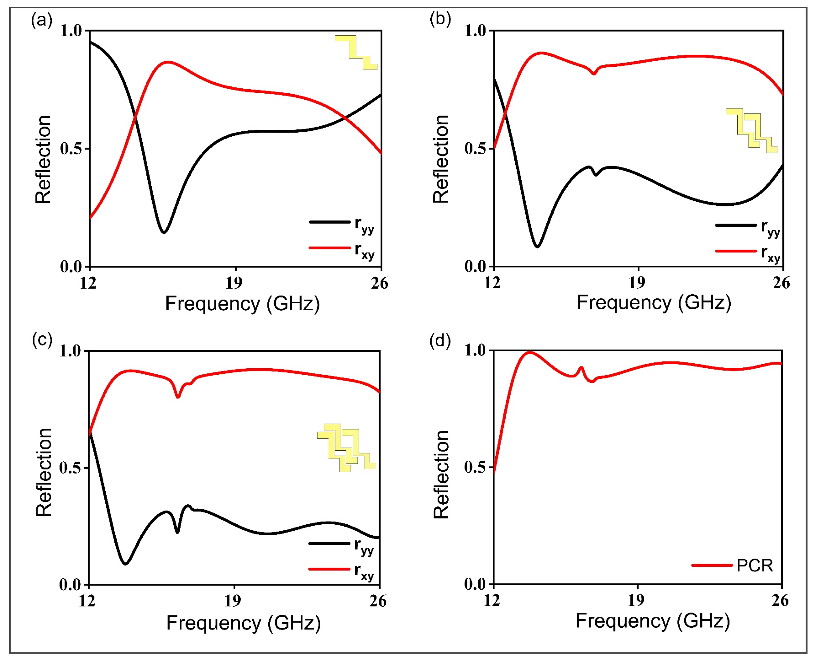
Figure 2 shows the optimization of the proposed polarizer. In this investigation, we are examining the TE polarization; however, it is showing equal effectiveness for the TM polarization because of the diagonal symmetry of the studied geometry. Cross-polarization conversion is seen to be taking place when the cross-polarized coefficient rises and there is a reduction in the co-polarized component coefficient. Figure 2a shows the first stage of the design of the polarization conversion. It is noticed that the cross-component of the polarizer reaches 80% at 15 GHz, and remains above 80% up to 18 GHz, and a further increase in the operating frequency reduces the cross-component. In the second stage, another stair-like resonator is added with a broken symmetry as shown in Figure 2b. Noticeably, the cross-polarization reflection coefficient is considerably increased, and it remains above 80% from 13 to 25 GHz. Further, another stair-like resonator is added in the unit cell with a broken symmetry. It is observed that the cross-polarization component is further increased, and the co-polarized reflection coefficient is reduced. However, adding another component resonator reduces the co-polarized coefficient. Therefore, Figure 2c shows the optimized results of the polarizer. Figure 2d shows the polarization conversion ratio (PCR); noticeably, this remains greater than 90% from 12.94 to 26 GHz, except for a small dip from 16.55 to 17.53 GHz. The PCR is determined by the following formula:
P C R = | r x y | 2 | r x y | 2 + | r y y | 2
In this formula, | r x y | 2 represents the squared magnitude of the reflection coefficient for the cross-polarized component, while | r y y | 2 denotes the squared magnitude of the reflection coefficient for the co-polarized component. This ratio quantifies the efficiency of polarization conversion, with higher PCR values indicating a more effective transformation of the incident polarization into the desired output state.
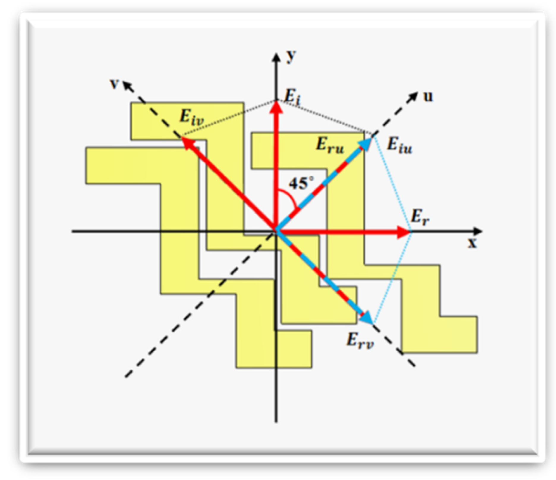
Further, we introduce a coordinate system of u- and v-axes to examine the anisotropy of the proposed structure, and with respect to the x-axes and y-axes, the axes are rotated at 45°. For investigation, the electromagnetic waves that are examined are the y-polarized incident electromagnetic waves. Figure 3 shows the anisotropic geometry of the polarization converter, which includes mutually perpendicular symmetric u- and v-axes. When the metasurface is hit with a y-polarized wave, the y-polarized wave splits into two components: E i y = u ^ E i u e j φ + v ^ E i v e j φ along the u- and v-axes. The two reflected components of the affecting waves after being combined together, resulting in an x-polarized wave, i.e., E x r = u ^ E r u e j φ u + v ^ E r v e j φ v where φ u and φ v are the r u and r v phases, respectively.
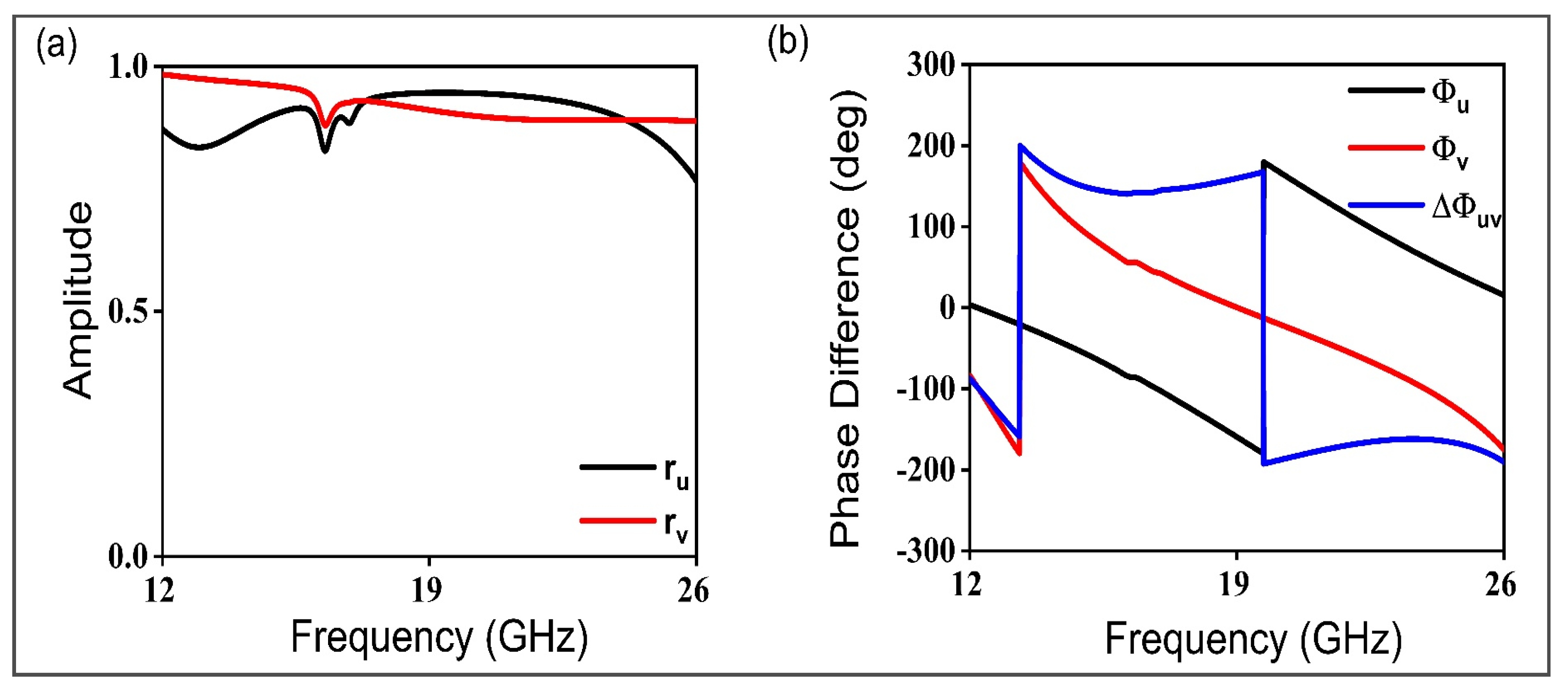
Most of the energy is considered as reflected because the initially proposed structure is with a thin layer of copper; hence, the amplitudes of r u and r v are almost the same. Due to the asymmetry of the structure, the alleged polarization converter is to be considered as an anisotropic material, resulting in a phase difference of Δ φ u v = φ u φ v = 180 ° between r u and r v , as depicted in Figure 3. In this situation, the component E r v will be opposite to E i v , and E r u will be the same as E i u , resulting in the synthetic field Er along the x-axis, which would validate the cross-polarization conversion. Further simulation results illustrated in Figure 4a,b justify the phase and amplitude conditions of r u and r v . It can be seen that there is a 180° phase difference between the amplitudes from 13 GHz to 26 GHz, and that the amplitudes of these constituents are approximately equal to unity, agreeing to the broadband polarization conversion.
The proposed polarization converter mechanism is as follows: When an electromagnetic wave comes into contact with a metasurface, electric and magnetic dipole moments are produced. The coupling of the magnetic and electric fields to the dipole moments is allowed by the bi-anisotropy of the structure as explained above. p m = p e e p e m p m e p m m E H , where p represents the electric dipole moments and m represents the magnetic dipole moments, respectively. p m e describes the magnetoelectric polarizability, and E , H represent the electric and magnetic field, respectively. The effective impedance of the metasurface is Ζ ω = μ ( ω ) ε ( ω ) , where ε ( ω ) and μ ( ω ) are the electric permittivity and magnetic permeability, respectively, while Ζ ( ω ) is the surface impedance of the metasurface. The reflection coefficient reaches unity when the metasurface impedance is larger than the impedance of free space Ζ ω r > Ζ ο , and the surface acts like a high-impedance surface (HIS), where ω r represents the resonance frequency and Ζ ο = 377 Ω is the free space impedance. In the case of a normal reflective surface, the reflected waves become out of phase, but here, incident electromagnetic waves will be reflected with unity amplitude and in-phase. As previously stated, the incoming wave polarization is turned by 90° when orthogonal components reflect at 180° or 0°, and cross-polarization conversion results in such a case. It is deduced that this structure acts as a common reflector for one component and as a high-impedance structure for another. For a better understanding of the physical mechanism of the polarization conversion, the surface current distributions on the top metasurface and bottom layer are taken up for 13.78 GHz, and 26 GHz, as shown in Figure 5.
It is depicted for 13.78 GHz that the surface currents on the top-most layer are antiparallel compared to ones on the bottom metallic layer. As shown in Figure 5a,b, this is indicative that the resonance at this frequency is magnetic in nature; therefore, the magnetic dipoles are the cause of the polarization conversion. For 26 GHz, the surface currents along the top layer are parallel-running compared to the ones of the bottom layer, indicating that the resonance is electric in nature, as shown in Figure 5c,d. Notably, the magnetic field in the metasurface substrate is enhanced by the top and bottom currents. As a result, the surface impedance rises, and the high-impedance surface condition is achieved. Phase reflection is caused by a current impedance mismatch in the y-direction, altering the x-directional flow of the current. Ultimately, the cross-polarization is attained, allowing a y-polarized wave to be converted to an x-polarized wave and an x-polarized wave to a y-polarized wave.
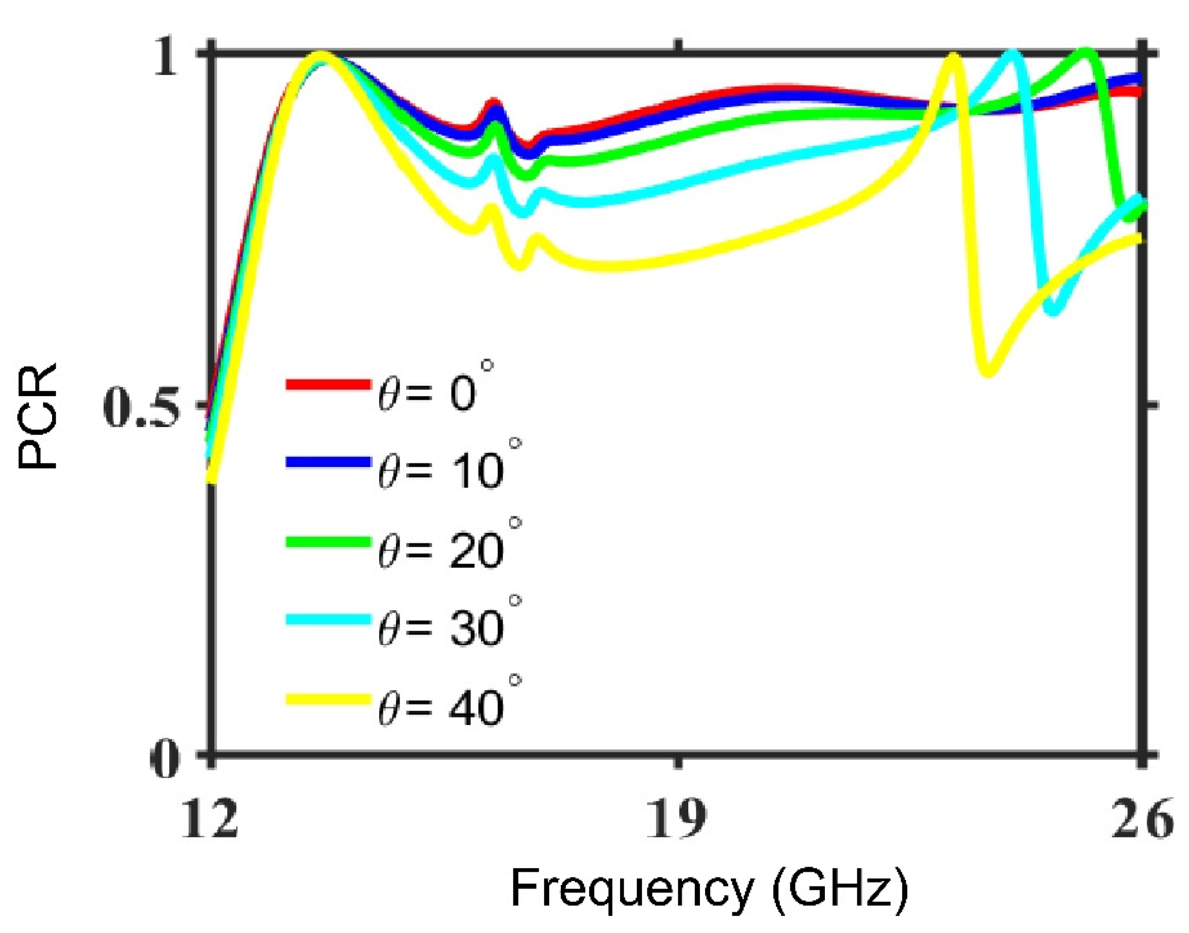
The anisotropic structures in the reflection mode can readily convert polarization, although they are sensitive to oblique incidence angles. It is possible to predict the stability and performance of a polarization conversion metasurface by analyzing its effectiveness over the span of a wide range of incidence angles. To evaluate the performance of the proposed metasurface polarization conversion, the simulation is performed with a wide variety of incidence angles from 0° to 40°. The incidence obliquity shows an effect on the polarization convertor’s performance regarded in terms of the PCR frequency dependence, as shown above in Figure 6. On the other hand, the normal incidence excitation used in the PCR spectrum is discussed in Figure 2b. We notice that in Figure 6, at θ = 10°, the structure is fairly stable for the operating bandwidth. At θ = 20°, the higher frequency band slightly decreases to 25.2 GHz. However, the overall performance is fairly stable for the operational frequencies. PCR > 80% is present in the range of frequency of 12.8 GHz to 25.6 GHz. At θ = 30° and 40°, the higher frequency band slightly decreases to 24 GHz and 23.1 GHz, respectively. It is assumed that throughout a large range of incidence angles, the specified metasurfaces can perform in a broad operating band. Similarly, when the incidence angle reaches θ = 30°, it can function over the frequency range of 12.8–16.3 GHz and 16.8 GHz to 24.3 GHz with a PCR of more than 80%. The PCR findings are likewise in good agreement at θ = 40°. Notably, the initial PCR peak persists at 13.7 GHz for all the incidence angle values chosen, making the alleged polarization converter unresponsive at this frequency of operation to incidence obliquity.
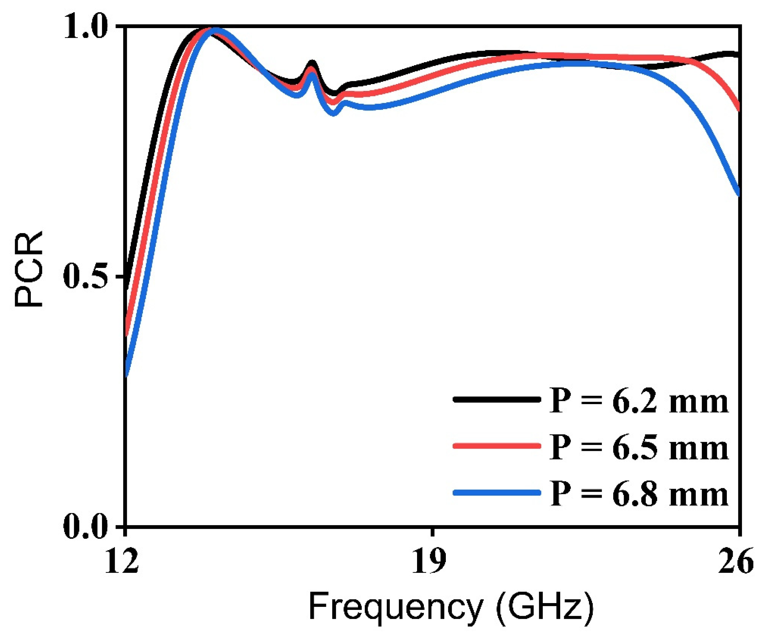
The proposed structure is further investigated for various periodicity values of the unit cell, namely, P = 6.2 mm, 6.5 mm, and 6.8 mm. However, the remaining parameters are kept the same. There is no significant effect on the performance of the alleged cross-polarization converter by the size increase in the unit cell. In the frequency range of 13–25 GHz, the value for PCR > 80% and approaches unity, as shown in Figure 7. Comparison of unit cell size, thickness and different parameters of our work with recently published papers can be seen in Table 1.

4. Experimental Results

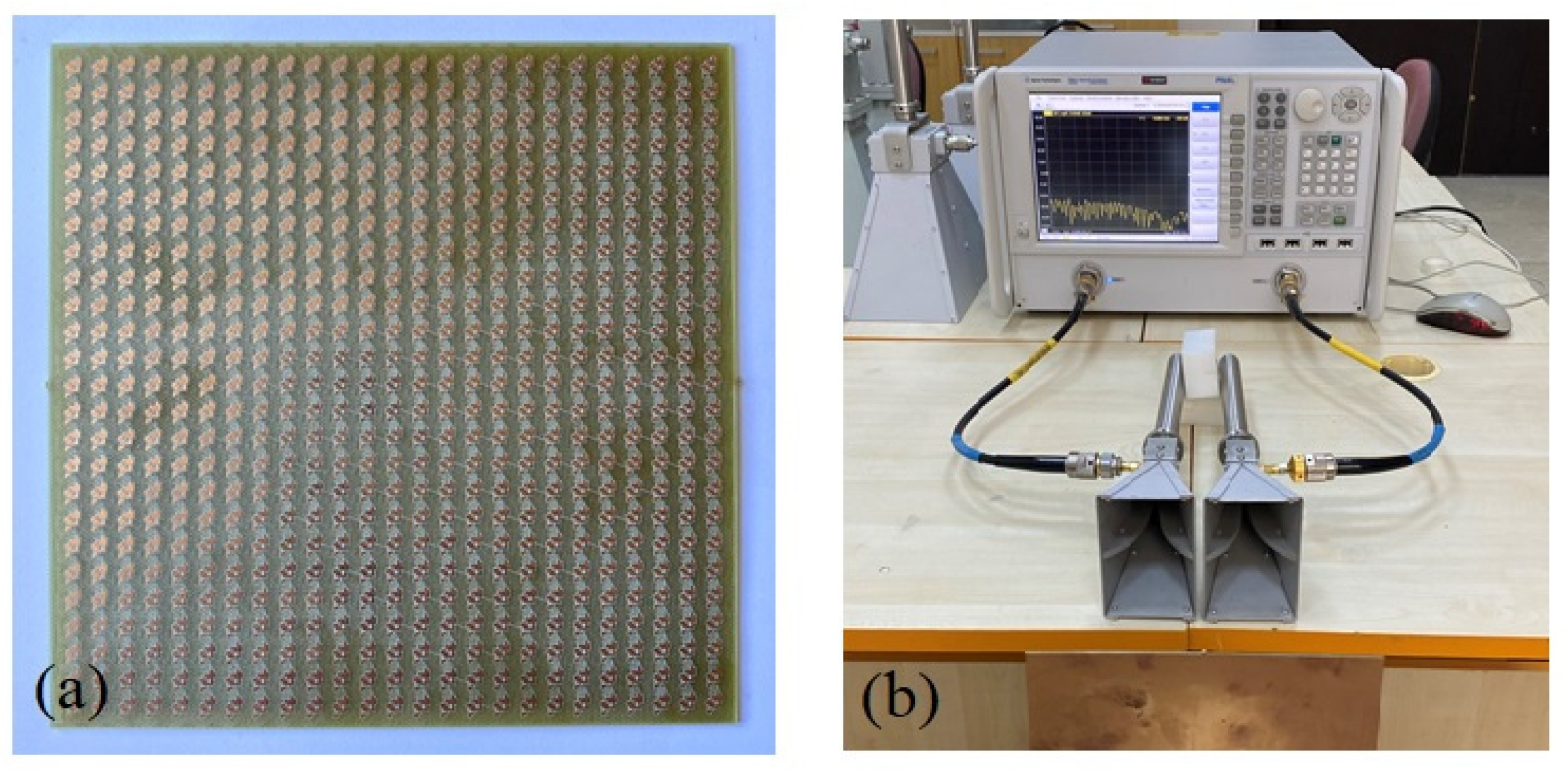
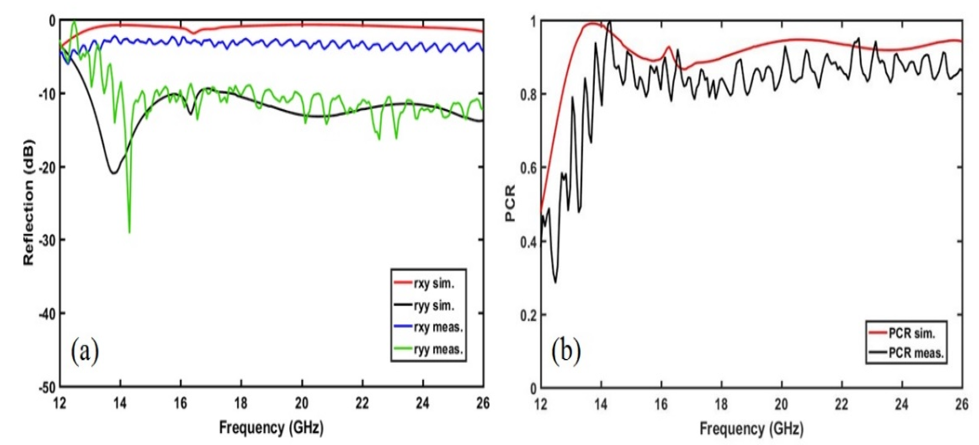
For the experimental studies, the allegedly proposed polarization converter was manufactured by the use of a PCB prototyping machine as illustrated in Figure 8a. It consisted of a 25 × 25 unit cell on a 160 mm × 160 mm substrate. The reflected field components were measured by a vector network analyzer (VNA) which can perform between 10 MHz and 43.5 GHz. During the measurement process, two types of horn antenna were employed considering the working frequency band of this study. One of them had an operating frequency band between 3 GHz and 18 GHz and the other one had between 15 GHz and 40 GHz. As evident from the experimental setup given in Figure 8b, for the orderly measurement of the co-polarized reflected field parameter, the horn antennas are to be placed in the same direction respective to the E-field. Then, one of the antennas was rotated 90° to obtain the cross-polar reflected field parameter. The obtained parameter results were normalized concerning free space measurements. Finally, these reflected field parameters and calculated PCR values were analyzed and compared to the simulated ones as demonstrated in Figure 9.
In Figure 9a, the results as a result of the simulation are compared in terms of the co-polarization and cross-polarization reflection. As shown in the figure above, the measured co-polarization reflection is greater than 3 dB at the frequency range from 13 GHz to 26 GHz. On the other hand, across this frequency range, the measured cross-polarization is <10 Db. When we compare the co-polarization reflection results between the simulated and measured ones, there is a small difference ranging from 1 dB to 2 dB. As to cross-polarization reflection comparison, the results are observed at almost the same level except for a frequency shift that occurred at around 14 GHz. In Figure 9b, the simulated and measured PCR results are examined. It is shown that the simulated PCR > 0.9 for the frequency ranges of 12.94 to 16.54 GHz and 17.54 to 26 GHz and the measured PCR > 0.8 for the frequency ranges between 14 GHz and 26 GHz. The minor deviations between the simulated and measured values stem from the imperfect fabrication process during the prototyping of the structure. As a consequence, the results show that the alleged polarization converter has high-efficiency and ultra-broadband characteristics.

5. Conclusions

From the aforesaid discussion, it can be concluded that the proposed metasurface-based polarizer works as a cross-polarization converter which is ultra-wideband, wide-angle, and highly efficient. The broadband cross-polarization conversion over a wide span of frequency range was achieved, i.e., 12–26 GHz. Overall, above 80% PCR was observed from the 12.3 to 26 GHz range. The physical mechanism behind the polarization achieved by the alleged polarizer, and the surface current of the top metasurface and bottom metallic surface were accounted for. Furthermore, a large range of oblique incidence angles was also covered by the polarization convertor. As a result, the features of a high-impedance surface were exhibited by the proposed metasurface, resulting in the reflection of an incident wave in its orthogonal counterpart. The proposed cross-polarization converter can be used in navigation systems, satellite communication, and imaging systems.

Author Contributions

Conceptualization, M.B.A. and F.R.; methodology, M.B.A. and F.R.; software, M.B.A. and F.R.; formal analysis, M.B.A. and F.R.; data curation, M.B.A. and F R.; validation, O.A. and M.K.; resources, M.A.B., O.A. and M.K.; writing—original draft, M.A.B.; writing—review and editing, M.B.A. and F.R.; funding acquisition, M.A.B.; supervision, M.A. and Q.A.N., project administration, M.A. and Q.A.N. All authors have read and agreed to the published version of the manuscript.

Funding

This research recieve no external funding.

Institutional Review Board Statement

Not applicable.

Informed Consent Statement

Not applicable.

Data Availability Statement

Data underlying the results presented in this paper are not publicly available at this time but may be obtained from the authors upon reasonable request.

Acknowledgments

The authors thank the Department of Electrical and Computer Engineering COMSATS University Islamabad for providing facilities to conduct this research.

Conflicts of Interest

The authors declare no conflicts of interest.

References

  1. Nicholls, L.H.; Rodríguez-Fortuño, F.J.; Nasir, M.E.; Córdova-Castro, R.M.; Olivier, N.; Wurtz, G.A.; Zayats, A.V. Ultrafast synthesis and switching of light polarization in nonlinear anisotropic metamaterials. Nat. Photonics 2017, 11, 628–633. [Google Scholar] [CrossRef]
  2. Arismar, C.S.; Da Costa, I.; Pinna, S.; Melo, S.; Laghezza, F.; Scotti, F.; Ghelfi, P.; Spadoti, D.; Bogoni, A. A novel dual-polarization and dual-band slotted waveguide antenna array for dual-use radars. In Proceedings of the 2016 10th European Conference on Antennas and Propagation (EuCAP), Davos, Switzerland, 10–15 April 2016; IEEE: New York, NY, USA, 2016; pp. 1–4. [Google Scholar]
  3. Wu, Z.; Li, L.; Li, Y.; Chen, X. Metasurface superstrate antenna with wideband circular polarization for satellite communication application. IEEE Antennas Wirel. Propag. Lett. 2015, 15, 374–377. [Google Scholar] [CrossRef]
  4. Qi, Y.; Zhang, B.; Liu, C.; Deng, X. Ultra-broadband polarization conversion meta-surface and its application in polarization converter and rcs reduction. IEEE Access 2020, 8, 116675–116684. [Google Scholar] [CrossRef]
  5. Beruete, M.; Navarro-Cía, M.; Sorolla, M.; Campillo, I. Polarization selection with stacked hole array metamaterial. J. Appl. Phys. 2008, 103, 053102. [Google Scholar] [CrossRef]
  6. Pors, A.; Nielsen, M.G.; Bozhevolnyi, S.I. Broadband plasmonic half-wave plates in reflection. Opt. Lett. 2013, 38, 513–515. [Google Scholar] [CrossRef]
  7. Ren, L.-S.; Jiao, Y.-C.; Li, F.; Zhao, J.-J.; Zhao, G. A dual-layer t-shaped element for broadband circularly polarized reflect array with linearly polarized feed. IEEE Antennas Wirel. Propag. Lett. 2011, 10, 407–410. [Google Scholar]
  8. Vasić, B.; Zografopoulos, D.C.; Isić, G.; Beccherelli, R.; Gajić, R. Electrically tunable terahertz polarization converter based on overcoupled metal-isolator-metal metamaterials infiltrated with liquid crystals. Nanotechnology 2017, 28, 124002. [Google Scholar] [CrossRef]
  9. Chen, P.; Ji, W.; Wei, B.-Y.; Hu, W.; Chigrinov, V.; Lu, Y.-Q. Generation of arbitrary vector beams with liquid crystal polarization converters and vector-photoaligned q-plates. Appl. Phys. Lett. 2015, 107, 241102. [Google Scholar] [CrossRef]
  10. Li, L.; Cui, T.J.; Ji, W.; Liu, S.; Ding, J.; Wan, X.; Li, Y.B.; Jiang, M.; Qiu, C.-W.; Zhang, S. Electromagnetic reprogrammable coding-metasurface holograms. Nat. Commun. 2017, 8, 197. [Google Scholar] [CrossRef]
  11. Yu, N.; Capasso, F. Flat optics with designer metasurfaces. Nat. Mater. 2014, 13, 139–150. [Google Scholar] [CrossRef]
  12. Akram, M.R.; Ding, G.; Chen, K.; Feng, Y.; Zhu, W. Ultrathin single layer metasurfaces with ultra-wideband operation for both transmission and reflection. Adv. Mater. 2020, 32, 1907308. [Google Scholar] [CrossRef] [PubMed]
  13. Zhang, J.; Wei, X.; Rukhlenko, I.D.; Chen, H.-T.; Zhu, W. Electrically tunable metasurface with independent frequency and amplitude modulations. ACS Photonics 2019, 7, 265–271. [Google Scholar] [CrossRef]
  14. Liu, B.; Zhu, W.; Gunapala, S.D.; Stockman, M.I.; Premaratne, M. Open resonator electric spaser. ACS Nano 2017, 11, 12573–12582. [Google Scholar] [CrossRef]
  15. Lin, D.; Fan, P.; Hasman, E.; Brongersma, M.L. Dielectric gradient metasurface optical elements. Science 2014, 345, 298–302. [Google Scholar] [CrossRef]
  16. High, A.A.; Devlin, R.C.; Dibos, A.; Polking, M.; Wild, D.S.; Perczel, J.; De Leon, N.P.; Lukin, M.D.; Park, H. Visible-frequency hyperbolic metasurface. Nature 2015, 522, 192–196. [Google Scholar] [CrossRef]
  17. West, P.R.; Stewart, J.L.; Kildishev, A.V.; Shalaev, V.M.; Shkunov, V.V.; Strohkendl, F.; Zakharenkov, Y.A.; Dodds, R.K.; Byren, R. All-dielectric subwavelength metasurface focusing lens. Opt. Express 2014, 22, 26212–26221. [Google Scholar] [CrossRef]
  18. Wen, J.; Chen, L.; Yu, B.; Nieder, J.B.; Zhuang, S.; Zhang, D.; Lei, D. All-dielectric synthetic-phase metasurfaces generating practical airy beams. ACS Nano 2021, 15, 1030–1038. [Google Scholar] [CrossRef]
  19. Tang, T.; Kanwal, S.; Lu, Y.; Li, Y.; Wu, S.; Chen, L.; Qian, Z.; Xie, Z.; Wen, J.; Zhang, D. 3D nano-printed geometric phase metasurfaces for generating accelerating beams with complex amplitude manipulation. Sci. China Phys. Mech. Astron. 2024, 67, 264211. [Google Scholar] [CrossRef]
  20. Wen, J.; Chen, L.; Chen, X.; Kanwal, S.; Zhang, L.; Zhuang, S.; Zhang, D.; Lei, D. Use of dielectric metasurfaces to generate deep-subwavelength nondiffractive bessel-like beams with arbitrary trajectories and ultralarge deflection. Laser Photonics Rev. 2021, 15, 2000487. [Google Scholar] [CrossRef]
  21. Lei, C.; Kanwal, S.; Yu, B.; Feng, J.; Tao, C.; Wen, J.; Zhang, D. Generation of high-uniformity and high-resolution Bessel beam arrays through all-dielectric metasurfaces. Nanophotonics 2022, 11, 967–977. [Google Scholar]
  22. Lin, B.-Q.; Guo, J.-X.; Huang, B.-G.; Fang, L.-B.; Chu, P.; Liu, X.-W. Wideband linear-to-circular polarization conversion realized by a transmissive anisotropic metasurface. Chin. Phys. B 2018, 27, 054204. [Google Scholar] [CrossRef]
  23. Chin, J.Y.; Lu, M.; Cui, T.J. Metamaterial polarizers by electric-field-coupled resonators. Appl. Phys. Lett. 2008, 93, 251903. [Google Scholar] [CrossRef]
  24. Singh, R.; Plum, E.; Menzel, C.; Rockstuhl, C.; Azad, A.; Cheville, R.; Lederer, F.; Zhang, W.; Zheludev, N. Terahertz metamaterial with asymmetric transmission. Phys. Rev. B 2009, 80, 153104. [Google Scholar] [CrossRef]
  25. Menzel, C.; Helgert, C.; Rockstuhl, C.; Kley, E.-B.; Tünnermann, A.; Pertsch, T.; Lederer, F. Asymmetric transmission of linearly polarized light at optical metamaterials. Phys. Rev. Lett. 2010, 104, 253902. [Google Scholar] [CrossRef] [PubMed]
  26. Ding, X.; Monticone, F.; Zhang, K.; Zhang, L.; Gao, D.; Burokur, S.N.; de Lustrac, A.; Wu, Q.; Qiu, C.-W.; Alù, A. Ultrathin pancharatnam–berry metasurface with maximal cross-polarization efficiency. Adv. Mater. 2015, 27, 1195–1200. [Google Scholar] [CrossRef]
  27. Ye, Y.; He, S. 90° polarization rotator using a bilayered chiral metamaterial with giant optical activity. Phys. Rev. Lett. 2010, 96, 203501. [Google Scholar] [CrossRef]
  28. Shi, H.; Zhang, A.; Zheng, S.; Li, J.; Jiang, Y. Dual-band polarization angle independent 90 polarization rotator using twisted electric-field-coupled resonators. Phys. Rev. Lett. 2014, 104, 034102. [Google Scholar] [CrossRef]
  29. Wang, S.-Y.; Liu, W.; Geyi, W. Dual-band transmission polarization converter based on planar-dipole pair frequency selective surface. Sci. Rep. 2018, 8, 3791. [Google Scholar] [CrossRef]
  30. Liu, Y.; Xia, S.; Shi, H.; Zhang, A.; Xu, Z. Dual-band and high-efficiency polarization converter based on metasurfaces at microwave frequencies. Appl. Phys. B 2016, 122, 178. [Google Scholar] [CrossRef]
  31. Huang, X.; Yang, D.; Yang, H. Multiple-band reflective polarization converter using u-shaped metamaterial. J. Appl. Phys. 2014, 115, 103505. [Google Scholar] [CrossRef]
  32. Jia, Y.; Liu, Y.; Guo, Y.J.; Li, K.; Gong, S.-X. Broadband polarization rotation reflective surfaces and their applications to rcs reduction. IEEE Trans. Antennas Propag. 2015, 64, 179–188. [Google Scholar] [CrossRef]
  33. Gao, X.; Yang, W.L.; Ma, H.F.; Cheng, Q.; Yu, X.H.; Cui, T.J. A reconfigurable broadband polarization converter based on an active metasurface. IEEE Trans. Antennas Propag. 2018, 66, 6086–6095. [Google Scholar] [CrossRef]
  34. Shi, H.; Li, J.; Zhang, A.; Wang, J.; Xu, Z. Broadband cross polarization converter using plasmon hybridizations in a ring/disk cavity. Opt. Express 2014, 22, 20973–20981. [Google Scholar] [CrossRef] [PubMed]
  35. Gao, X.; Han, X.; Cao, W.-P.; Li, H.O.; Ma, H.F.; Cui, T.J. Ultrawideband and high-efficiency linear polarization converter based on double v-shaped metasurface. IEEE Trans. Antennas Propag. 2015, 63, 3522–3530. [Google Scholar] [CrossRef]
  36. Mei, Z.L.; Ma, X.M.; Lu, C.; Zhao, Y.D. High-efficiency and wide-bandwidth linear polarization converter based on double u-shaped metasurface. AIP Adv. 2017, 7, 125323. [Google Scholar] [CrossRef]
  37. Yang, J.J.; Cheng, Y.Z.; Ge, C.C.; Gong, R.Z. Broadband polarization conversion metasurface based on metal cut-wire structure for radar cross section reduction. Materials 2018, 11, 626. [Google Scholar] [CrossRef]
  38. Rubin, N.A.; Zaidi, A.; Dorrah, A.H.; Shi, Z.; Capasso, F. Jones matrix holography with metasurfaces. Sci. Adv. 2021, 7, eabg7488. [Google Scholar] [CrossRef]
  39. Zheng, C.; Liu, J.; Li, H.; Wang, M.; Zang, H.; Zhang, Y.; Yao, J. Terahertz metasurface polarization detection employing vortex pattern recognition. Photonics Res. 2023, 11, 2256–2263. [Google Scholar] [CrossRef]
  40. Zheng, C.; Li, H.; Liu, J.; Wang, M.; Zang, H.; Zhang, Y.; Yao, J. Full-Stokes metasurface polarimetry requiring only a single measurement. Photonics Res. 2024, 12, 514–521. [Google Scholar] [CrossRef]
  41. Sui, S.; Ma, H.; Wang, J.; Feng, M.; Pang, Y.; Xia, S.; Xu, Z.; Qu, S. Symmetry-based coding method and synthesis topology optimization design of ultra-wideband polarization conversion metasurfaces. Phys. Rev. Lett. 2016, 109, 014104. [Google Scholar] [CrossRef]
  42. Zhou, Y.; Kravchenko, I.I.; Wang, H.; Zheng, H.; Gu, G.; Valentine, J. Multifunctional metaoptics based on bilayer metasurfaces. Light Sci. Appl. 2019, 8, 80. [Google Scholar] [CrossRef] [PubMed]
  43. Ori, A.; Almeida, E.; Prior, Y.; Ellenbogen, T. Composite functional metasurfaces for multispectral achromatic optics. Nat. Commun. 2017, 8, 14992. [Google Scholar]
  44. Mansouree, M.; Kwon, H.; Arbabi, E.; McClung, A.; Faraon, A.; Arbabi, A. Multifunctional 2.5 D metastructures enabled by adjoint optimization. Optica 2020, 7, 77–84. [Google Scholar] [CrossRef]
  45. Tauqirm, A.; Rahim, A.A.; Bilal, R.M.H.; Noor, A.; Maab, H.; Naveed, M.A.; Madni, A.; Ali, M.M.; Saeed, M.A. Ultrawideband cross-polarization converter using anisotropic reflective metasurface. Electronics 2022, 11, 487. [Google Scholar] [CrossRef]
  46. Nguyen, T.M.; Phan, H.L.; Vu, D.L.; Nguyen, T.Q.H.; Kim, J.-M. Ultra-wideband and high-efficiency cross-polarization conversion using a double split ring shaped metasurface for C, X, and Ku-band applications. AIP Adv. 2022, 12, 115002. [Google Scholar] [CrossRef]
  47. Babar, K.; Chen, J.; Yingzeng, Y.; Ren, J.; Ullah, S.; Khan, W.U.R. High efficiency and ultra-wideband polarization converter based on an L-shaped metasurface. Opt. Mater. Express 2021, 11, 1343–1352. [Google Scholar]
  48. Yu, H.; Wang, X.; Su, J.; Qu, M.; Guo, Q.; Li, Z.; Song, J. Ultrawideband and high-efficient polarization conversion metasurface based on multi-resonant element and interference theory. Opt. Express 2021, 29, 35938–35950. [Google Scholar] [CrossRef]
Figure 1. Schematic of the proposed polarization converter: (a) front view; (b) side view.
Photonics 11 00863 g001
Figure 2. Simulation results of the proposed metasurface (ac) co- and cross-polarization components r y y and r x y ; (d) polarization conversion ratio (PCR). The yellow subfigure in the corner of each graph (ac) represents the design of unit cell used to calculate reflection curves.
Photonics 11 00863 g002
Figure 3. Scheme representing the decomposing of the orthogonal components.
Photonics 11 00863 g003
Figure 4. Simulation results of the proposed metasurface: (a) The reflected amplitudes of r u and r v . (b) Phase difference.
Photonics 11 00863 g004
Figure 5. Surface current distributions of the alleged polarizer of the top and bottom metallic layers at the resonant frequencies: (a,b) 13.78 GHz; (c,d) 26 GHz.
Photonics 11 00863 g005
Figure 6. Frequency-dependent PCR plots at different oblique incidence angles.
Photonics 11 00863 g006
Figure 7. Frequency-dependent PCR plots at different sizes of the unit cell.
Photonics 11 00863 g007
Figure 8. (a) Prototype of the polarization converter and (b) the experimental setup.
Photonics 11 00863 g008
Figure 9. Measured and simulated results of the proposed metasurface: (a) co- and cross-polarization components r y y and r x y ; (b) polarization conversion ratio (PCR).
Photonics 11 00863 g009
Table 1. Comparison of unit cell size, thickness and different parameters of our work with recently published papers.
Ref.Unit Cell Size
(mm)
Thickness (mm)Operating Bandwidth (GHz)Polarization
Conversion
PCR
[35]6.41.612.4–27.96LP to LPPCR > 0.9
[45]71.613–26LP to LPPCR > 0.9
[46]140.84–14LP to LPPCR > 0.93
[47]838.6–22LP to LP,
LP to CP
PCR > 0.9
[48]103.53.37–22.07LP to LPPCR > 0.9
Our work6.21.612.94–16.54,
17.54–26
LP to LPPCR > 0.9
Disclaimer/Publisher’s Note: The statements, opinions and data contained in all publications are solely those of the individual author(s) and contributor(s) and not of MDPI and/or the editor(s). MDPI and/or the editor(s) disclaim responsibility for any injury to people or property resulting from any ideas, methods, instructions or products referred to in the content.