Article

Structural Diagnosis of Solid Rocket Motors Using Neural Networks and Embedded Optical Strain Sensors

by
Georgia Korompili
1,
Nicholaos Cholevas
1,2,
Konstantinos N. Anyfantis
2,
Günter Mußbach
3 and
Christos Riziotis
1,4,*
1
Theoretical & Physical Chemistry Institute, National Hellenic Research Foundation, 11635 Athens, Greece
2
School of Naval Architecture and Marine Engineering, National Technical University of Athens, 15780 Athens, Greece
3
Bayern-Chemie GmbH (MBDA Germany), 84544 Aschau am Inn, Germany
4
Defence & Security Research Institute, University of Nicosia, CY-2417 Nicosia, Cyprus
*
Author to whom correspondence should be addressed.
Photonics 2024, 11(9), 799; https://doi.org/10.3390/photonics11090799
Submission received: 25 June 2024 / Revised: 23 August 2024 / Accepted: 24 August 2024 / Published: 27 August 2024
(This article belongs to the Special Issue Editorial Board Members’ Collection Series: Photonics Sensors)

Abstract

:
The main failures that could deteriorate the reliable operation of solid rocket motors (SRMs) and lead to catastrophic events are related to bore cracks and delamination. Current SRMs’ predictive assessment and damage identification practices include time-consuming and cost-demanding destructive inspection techniques. By considering state-of-the-art optical strain sensors based on fiber Bragg gratings, a theoretical study on the use of such sensors embedded in the circumference of the composite propellant grain for damage detection is presented. Deep neural networks were considered for the accurate prediction of the presence and extent of the defects, trained using synthetic datasets derived through finite element analysis method. The evaluation of this combined approach proved highly efficient in discriminating between the healthy and the damaged condition, with an accuracy higher than 98%, and in predicting the extent of the defect with an error of 2.3 mm for the bore crack depth and 1.6° for the delamination angle (for a typical ~406 mm diameter grain) in the worst case of coexistent defects. This work suggests the basis for complete diagnosis of solid rocket motors by overcoming certain integration and performance limitations of currently employed dual bond stress and temperature sensors via the more scalable, safe, sensitive, and robust solution of fiber optic strain sensors.

1. Introduction

Solid rocket motors (SRMs) stand as pivotal components across aerospace and defense applications, powering satellite launches, missile systems, and space exploration missions as solid rocket boosters (SRB). A typical schematic of an SRM structure is illustrated in Figure 1a. Despite their widespread use, SRMs face inherent vulnerabilities such as internal bore cracks and delamination, which can pose threats to their performance, reliability, and safety [1]. Timely detection of these defects is paramount to averting catastrophic failures and ensuring mission success [2].
Conventional inspection methods for SRMs typically involve visual scrutiny and labor-intensive experimental procedures on the mechanical properties of the propellant grain [3] or X-ray imaging, which can be time-consuming, expensive, and, most importantly, often destructive for the SRMs. Additionally, these testing protocols are impractical for implementation on user premises such as air bases, thus necessitating logistic efforts associated with high financial costs and equally important time delay costs. In recent years, there has been a surge in the development of structural health monitoring (SHM) systems to support condition-based maintenance (CBM) strategies for efficient inspection and monitoring of SRMs [4]. These systems particularly employ piezoelectric or dual bond stress and temperature (DBST) sensors [4,5,6,7], placed on the interface between the propellant and the casing of the SRM, as can be seen in Figure 1b, or more recently, optical fiber strain sensors [8] embedded in the grain. These sensors can detect changes in the motor’s mechanical behavior, which can be indicative of the presence of internal defects [9].
Recently, there has also been a strong interest in developing automated defect detection systems for SRMs using machine learning (ML) techniques such as neural networks (NN) [10,11,12,13] that can be trained to recognize patterns in large amounts of data. These have been successfully applied to a variety of image, signal, and feature processing applications. Particularly, concerning the SHM and diagnosing of the SRMs, there have been a few approaches evaluating the performance of the several NN-based systems in the identification of bore cracks, delamination, or both [11]. However, these approaches cover specific areas of the problem, without reporting on the potential to discriminate the healthy from the damaged state or perform complete diagnoses by predicting the type of defect and the extent of it. Moreover, the majority of the reported projects and research on the issue of SHM of SRMs refer to the use of DBST sensors [14]. To our knowledge, there is no reported work on the performance of optical fiber strain sensors [15,16,17], such as fiber Bragg grating (FBG)-based sensors, along with the employment of machine learning techniques for the detection of defects in SRMs. This type of optical sensor was introduced to reduce the minimum detectable defect extent to much lower values without implementing electrical wiring into the motor, as was reported in several studies [18,19,20]. Furthermore, optical sensors have some uniquely favorable characteristics, such as their low weight, inherent electromagnetic interference immunity, and inherent safety characteristics in explosive or flammable environments. Additionally, optical fibers can have quasi-distributed sensing capabilities by introducing multiple FBGs into a single optical fiber, while they can be interrogated remotely, from a distance through a low loss optical fiber [16,17,21] through optical transmission, meaning that the electronic-based interrogation unit and any electric power supply system can be positioned far away from the SRM. The incorporation of an optical fiber with a nominal typical diameter of 125 μm or even down to 50 μm is possible without mechanical disturbance of the propellant or degradation of the mechanical properties of the SRM system, as could be the case with DBST sensors, where invasive physical openings on the external casing surface are needed for embedding the sensors. Another important characteristic of the fiber optic-based strain sensors is their ability to be embedded anywhere in the propellant by following proper procedures during the propellant casting process, thus providing the potential for monitoring higher deformations and higher strain changes in comparison to DBST sensors that are fixed close to the casing with limited monitored deformations.
While the capabilities of the FBG-based strain sensors appear promising in monitoring the structural integrity of the SRM [21], a diagnostic tool targeting to the detection of localized defects, such as bore cracks or delamination, based on the strain field distribution has to be re-developed to compare its performance with previously studied works that are based on stress sensors. The performance of ML, or specifically, NN-based techniques [22,23] using optical strain sensors, has been evaluated as a SHM tool in several generic diagnostic applications [23,24,25,26,27,28]. However, the field remains open to further investigation, particularly in the case of challenging SRM-related studies concerning the detection of defects or ageing and degradation of the propellant. The specific issues that need to be studied are as follows: (a) the comparison of the hoop strain field distribution, monitored using FBG-based strain sensors, with the radial stress field distribution, monitored by the currently used DBST sensors; (b) the feasible location of the recently introduced FBG-based strain sensors in the SRM and the way this location affects the performance and accuracy of detection of localized defects; and (c) the theoretically expected performance of a NN-based SRM diagnostic tool, finely tuned for the specific application and the use of optical-based strain sensors, to investigate the potential of these sensors for achieving higher accuracies in SRM health monitoring.
In this paper, we focus on the above fields of interest, and we particularly explore the feasibility of an NN-based diagnostic tool for the identification of defects in an SRM by assessing its trainability and performance. Due to the lack of experimental data, we use two-dimensional (2D) simulations of the cross section of the SRM to build a dataset of strain data in specific positions of the circular section of the motor in order to feed a two-stage deep NN-based system and to perform structural health diagnosis of the SRM. We evaluate the performance of the networks to accurately discriminate healthy from damaged states of the SRM, to identify the type of the present defect in the case of the damaged state, and to predict the spatial extent of the defects. In our analysis, we also investigate the impact of critical factors on the prediction error. These factors are defined at the simulation level and concern the angular position of the defect, the coexistence of two different defects—bore crack and delamination—and the relative angular distance between them. Our results show that deep neural networks can achieve a high accuracy in identifying both bore cracks and delamination in solid rocket motors, with an overall accuracy of over 98% on our dataset and a maximum root mean square error (RMSE) of 2.3 mm for bore cracks and 1.57°. These results were obtained using only four strain sensors in a typical SRM case with grain diameter of 406 mm. We discuss the implications of these results for the development of automated inspection systems for SRMs, and we identify several areas for future research. Overall, our work demonstrates the potential of machine learning techniques in conjunction to recently introduced optical fiber-based strain sensing capabilities in improving the safety and reliability of critical propulsion systems.

2. SRM Physical Model and Finite Element Analysis

2.1. SRM Model and Defect Definition

A typical SRM geometry is considered in this study. It mainly consists of a metallic case, an insulation layer, and the contained solid elastomeric composite material (propellant grain) itself. In general, the SRMs are structured in a cylindrical arrangement with various possible bore shapes depending on the specific SRM functional characteristics such as acceleration and thrust. Here, the simplified case of a cylindrical bore is assumed.
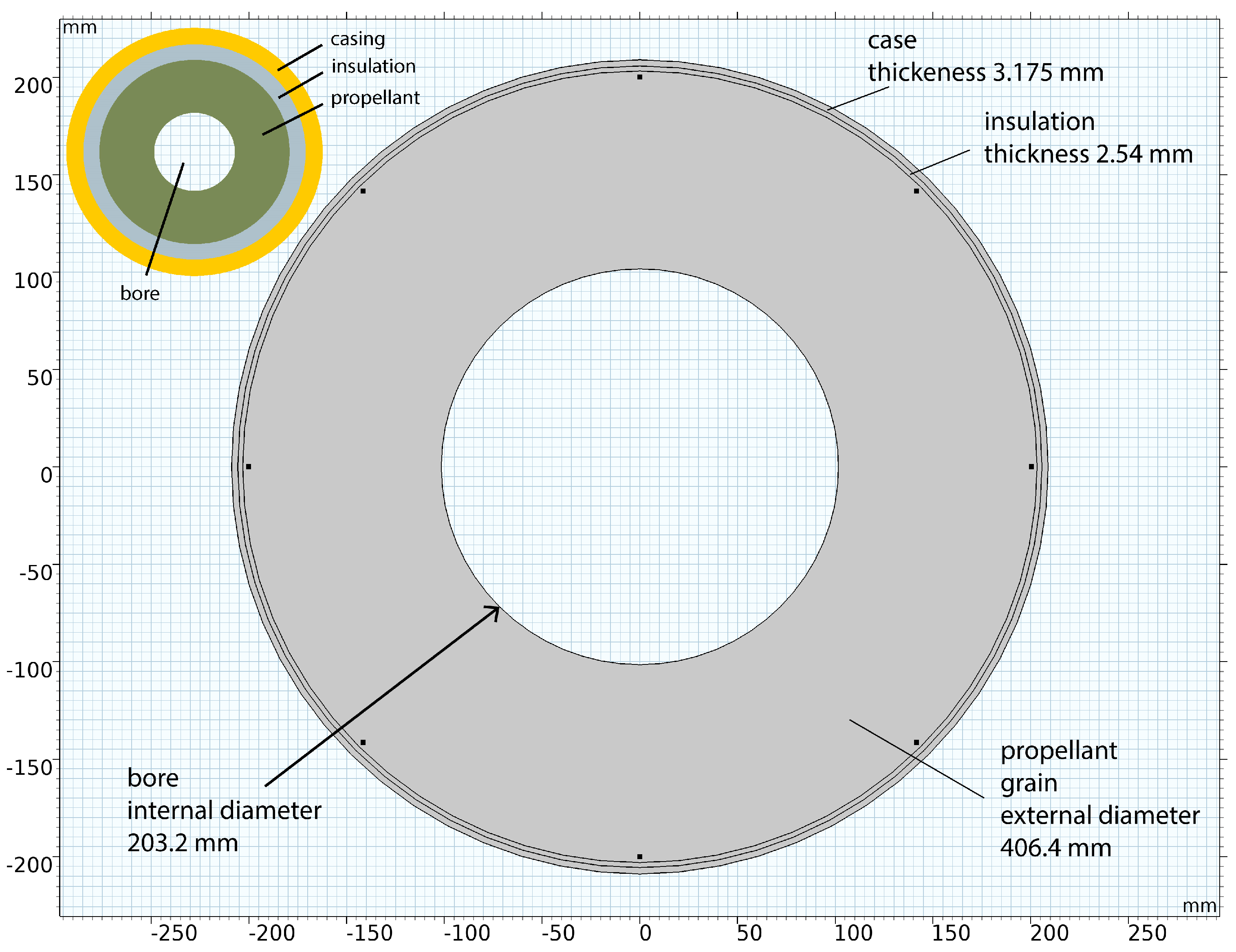
The entire propellant structure considered here is axisymmetric, with the bore diameter (inner diameter) being 203.2 mm and the outer diameter being 406.4 mm. The propellant material is a typical composite grain of hydroxyl-terminated polybutadiene (HTPB)/ammonium perchlorate (HTPB/AP). The insulation is modeled as a thin layer attached to the propellant domain, with a thickness of 2.54 mm, whose material properties correspond to an ethylene propylene diene monomer (EPDM). The insulation layer is attached to a thin stainless-steel casing with a thickness of 3.125 mm. The material properties participating in the model are given in Table 1, along with the information of the inner and outer radius of the designed domains (Figure 2). They were treated as isotropic linear elastic materials. This assumption is a simplification that is not expected to affect the final results of the simulation, as the model is subjected to a stationary regime, simulating the stress and strain fields due to the transition from the initial curing and stress-free temperature, which here is set to 71 °C (or more usually in the range 50−60 °C), down to extreme conditions of −51 °C.
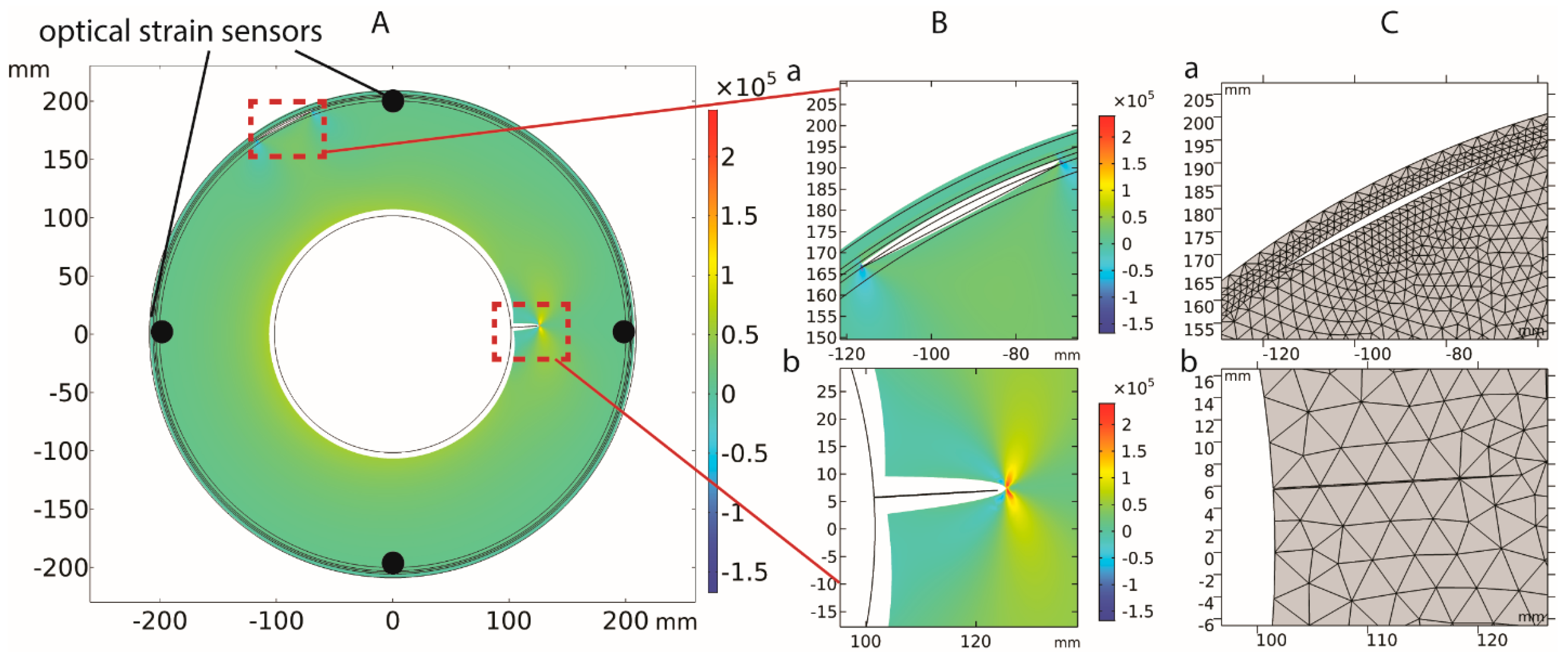
In this work, a finite element analysis (FEA), particularly the Structural Mechanics module of the COMSOL Multiphysics software (COMSOL, Inc., Burlington, MA 01803, USA), is used to study and analyze the strain distribution in the presence of thermal loads and various defects and to identify also the response of the strain sensors in the SRM under various conditions. The time and computational requirements of the study of SRM are reduced without a loss of information in a simplified two-dimensional (2D) structure of the cross-section of a center-perforated SRM, simulated using the plane strain approximation method. In Figure 2, the modeled grain structure is illustrated. For the specific case illustrated in Figure 3, we used an example of a bore crack of depth a = 22.54 mm located at 3.271° and a delamination of angle φ = 14.97° located at 117.55°. The strain field distribution in με is illustrated on the slice of the simulated cylindrical geometry of the SRM. The strain sensor locations are also depicted at 0°, 90°, 180° and 270°. The strain field distribution and the corresponding deformation is illustrated in the regions of both the bore crack and the delamination, with the deformation scale factor being set to 1.
In the conducted simulations, we assumed two types of possible flaws in the SRM: bore cracks and delamination. The designs of these flaws are depicted in Figure 3. In the case of the bore crack, the defect has a depth a within the range of (0.1 mm, 40 mm) with the corresponding gap width being equal to a/200. The delamination corresponds to an arc in the range φ (1°, 19°), with the gap appearing between the curved insulation boundary and a line segment between the limit points of the debonded region, which corresponds to the propellant domain boundary. Outside the debonded region, the two neighboring material domains—the insulation and the propellant—share a common interface corresponding to a curved arc with a radius equal to the outer radius of the propellant and an arc angle equal to 360° − φ. Based on the conducted calculations, the gap between the two domains after the thermal expansion is not expected to exceed 3 mm in the case of the largest debonding region angle examined. Provided that the simulations assume a homogeneously distributed temperature during the examined thermal cycle, this design can be considered accurate.
The study assumes the use of four strain sensors that are evenly distributed in the circular perimeter of the SRM, thus having an angular distance of 90° from each other and a 45° maximum angular distance from any defect in the worst-case scenario. The sensors are considered to be placed in the grain close to the interface between the propellant and the insulation, particularly with a distance of 3 mm from this interface. Such individual strain sensors are essentially multiple discrete FBGs integrated into a single optical fiber with a typical diameter of 125 μm or less. The study of the optimal number of sensors that should be placed per circular perimeter of the SRM is considered to be beyond the scope of this study; however, a short comparison with the preliminary study in the case of eight sensors and its impact on the diagnosis improvement is addressed in the Discussion section.

2.2. Hoop Strain Distribution vs. Radial Stress Distribution

Following the previously described SRM study formulation based on newly proposed strain distribution monitoring, it would be important to provide a direct comparison between the details and capabilities of strain and stress sensing, where the latter corresponds to the approach currently used in industry by DBST devices. It is expected that this comparison will highlight and demonstrate the differences and identify the advantages of strain monitoring employing optical strain sensors such as FBGs.
The key element of the present work is the use of optical-based strain sensors for the detection of defects in SRMs. Comparable studies in literature targeting SRM diagnosis and defect prediction focus on the use of stress sensors, particularly DBSTs. The transition to the recently introduced FBG-based strain sensors emerges with open questions regarding: (a) the differences between the strain field distribution and the stress field variations when a defect is present in the SRM, and (b) the consequent capabilities of the strain sensors to accurately detect the presence of a defect. Particularly, when a defect occurs in the SRM, it typically induces localized stress concentrations in the vicinity of the defect. These stress concentrations can lead to variations in the radial stress field, which DBST sensors are primarily designed to detect. However, since stress concentrations tend to dissipate more rapidly in the radial direction compared to the circumferential direction, the changes in the radial stress field may be more localized around the defect site. On the other hand, an equivalent defect can also cause significant changes in the hoop strain field along the circumference of the motor.
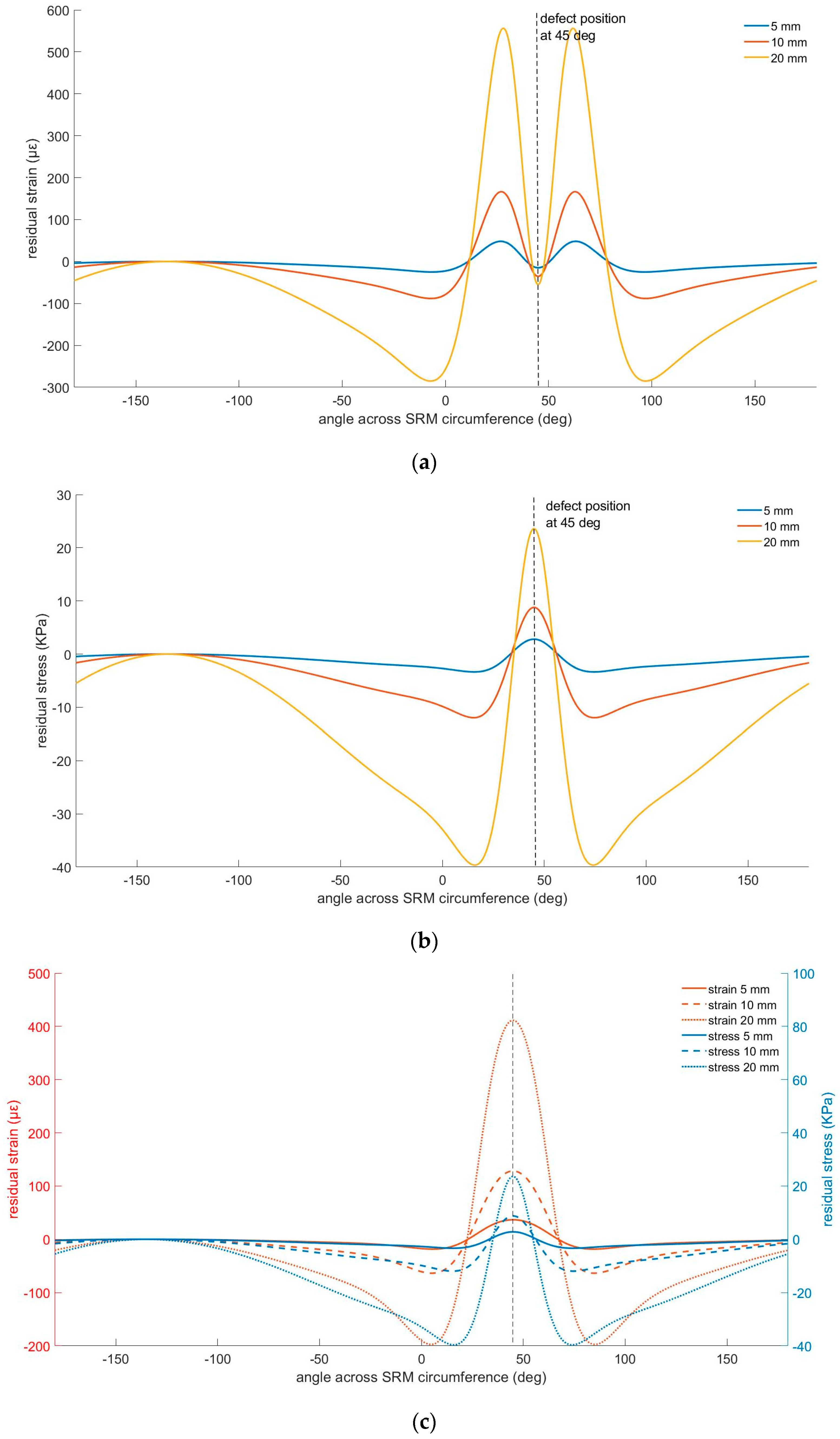
Hoop strain, which FBGs can measure, provides information about the circumferential deformation of the grain. The occurring defects can introduce disruptions in the structural integrity of both the casing and the grain, leading to alterations in the hoop strain distribution over a broader area compared to the localized changes in the radial stress field. However, the practical issues related to the sensor placements—specifically, the DBST sensors are placed in the insulation–casing interface, while FBGs should be placed within the propellant material—reduce the above-described effect, since the propellant is typically composed of a more homogeneous material compared to the casing material. Therefore, its structural integrity is less affected by localized defects. Figure 4 illustrates the radial stress and hoop strain field distribution in the typical radial position of the corresponding sensors. Particularly, Figure 4a depicts the residual strain in the grain 3 mm away from the insulation layer, and Figure 4b presents the residual stress in the middle of the insulation layer for three typical defects in the bore region (bore cracks) at depths of 5 mm, 10 mm, and 20 mm, respectively. In Figure 4c, we present the strain and stress field variation when studied at the same radial distance of the SRM, particularly in the middle of the insulation layer.
Based on the study of the above graphs (Figure 4), we can conclude that: (a) a crack of double depth (10 mm compared to 5 mm) provokes a ~3.5 times higher maximum value in both the strain and the stress fields, irrespective of the location of the maxima; (b) the same happens for a bore crack depth that is four times deeper than the initial depth (20 mm compared to 5 mm crack), which provokes an ~11.5 times higher maximum value in both the stress and strain fields; (c) the variations in the hoop strain field are extended over a larger area compared to the variations in the stress field for the same crack, and they are likely to be detected even from sensors located even 90° away from the crack. This observation is further enhanced by the comparison of the absolute residual strain and stress values with the corresponding sensor resolutions, being ~4με for the FBGs and 10 KPa for the DBSTs. Particularly, the maximum change in the residual stress due to the presence of a bore crack at a 20 mm depth is 4 times the corresponding DBSTs stress resolution, while the maximum change in the residual strain exceeds 130 times the corresponding FBG strain resolution. Similar results are extracted based on the study shown in Figure 4c, where it can be seen that strain field variations are expected to be larger compared to stress field variations when measured using sensors located in the middle of the insulation layer. The strain fields tend to show more widespread variations due to the overall deformation of the material around the crack, while the stress field variations are highly localized around the crack tips. Therefore, strain measurements provide a broader indication of the defect’s presence and impact.
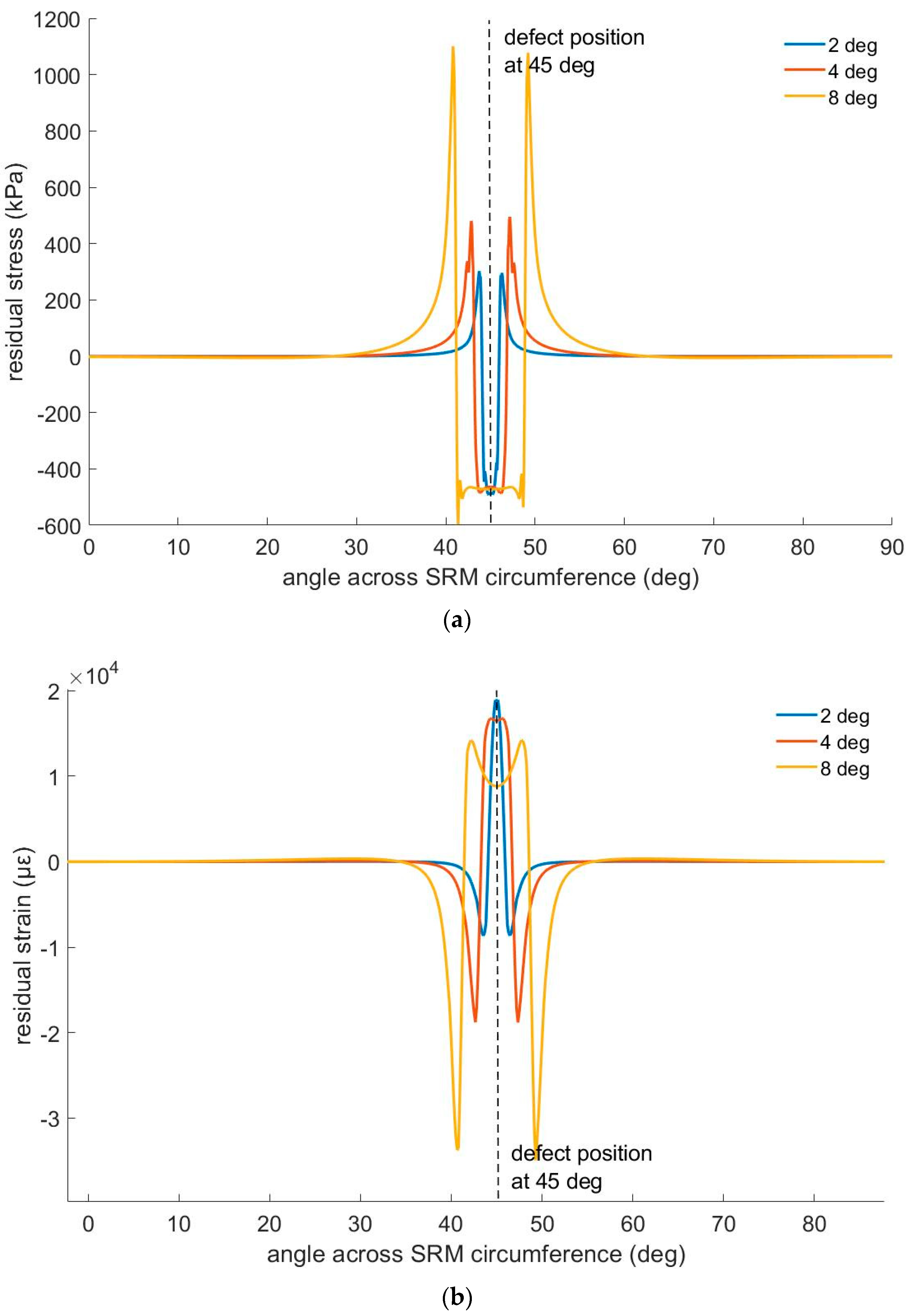
Similarly, a delamination present in the interface between the propellant and the insulation layer produces a stress and strain field distribution shown in the following graphs based on simulation results (Figure 5). Particularly, in Figure 5a, we present the residual stress in the middle of the insulation layer, while in Figure 5b, we present the residual strain in the grain, 3 mm away from the propellant–insulation interface, provided the presence of 2°, 4°, and 8° delamination. The study of the provided data shows that the stress field variation due to the presence of a delamination of 4° is detectable by the stress sensors placed in the middle of the insulation layer only 10° away from the position of the defect (delamination position at 45°, sensor position for accurate detection at 35°). The corresponding strain field distribution presents a detectable change more than 37° away from the location of the defect (delamination position at 45°, sensor position for accurate detection at 7.5°). It is also proven that a delamination of 8° produces a maximum change in the strain field approximately 8500 times the expected strain resolution of the optical fiber strain sensors (expected to be at least 4 με), while the same delamination produces a maximum stress field change that is only110 times higher than the stress resolution of DBSTs (expected to be 10 kPa).
Based on the above observations, it was necessary to study the capabilities of SRM diagnosis and defect detection using FBG-based strain sensors, aiming at determining: (a) the minimum defect that can be detected, (b) the accuracy of defect size prediction, and (c) the corresponding accuracy of diagnosis when two types of defects are present (bore cracks and delamination). The following sections focus on these emerging issues, which comprise the main contribution of this work.

2.3. Healthy State and Damaged State of SRM

Discrimination between the healthy and the damaged state (Level I SHM) of the SRM is a typical problem that may be addressed using classification neural networks. The threshold values of all participating parameters, related to the extent and location of defects, correspond to the discrimination between the healthy state and the damaged state of the SRM. These are selected according to the minimum detectable flaws based on the employed optical strain sensors. Thus, all cases with a bore crack depth larger than the corresponding threshold of the minimum detectable bore crack depth belong to the damaged state, while the cases with smaller crack depths belong to the healthy state. The same applies for the delamination angle. For the determination of the minimum detectable defect extent, it is assumed in a conservative scenario that the resolution of these sensors is 4 με (which is achievable using current FBG technology), and the worst-case scenario for the position of the defect with respect to the sensing element is set to its maximum, equal to 45°, provided the use of four sensors that are evenly distributed on the SRM perimeter.
In order to define the minimum detectable bore crack, a simulation with variable bore crack depth a in the range of [0.1 mm, 15 mm] with a step of 0.1 mm for the range of [0.1 mm, 3 mm] and a step of 1 mm for the range of (3 mm, 15 mm] was performed for a bore crack located at 45°. The detection of the bore crack is assured when the absolute difference between the strain value of the sensor closest to the flaw and the most distant sensor is higher than 4 με, provided that the location of the flaw at 45°, the nearest sensor is at 0° (or equally 90°), and the most distant sensor is located at 180° (or equally 270°). Figure 6 illustrates this strain difference, where each plot is presented with reference to the corresponding strain value of the sensor located at 180°. Particularly, Figure 6 illustrates the strain field across the circular path with a radius equal to the radius of the strain sensor locations, 3 mm away from the interface between the insulation and the propellant inside the grain, which is the circular path of interest in this study. Based on the zoomed-in region illustrated in Figure 6Aa, it is depicted that a minimum depth of 2.2 mm can be detected using a sensor located at an angular distance of 45°. The same process was repeated for the delamination case, with the parameter of the delamination angle varying in the range of [1°, 10°] with a step of 1°. The minimum detectable delamination extends in a region with an angular size equal to 7°. This process is based on a rather pragmatic consideration of the healthy state depending on the accuracy of the employed sensing technology.

2.4. Strain Data Generation Using FEA Models

To produce an adequately large dataset for the analysis and NN training, we divided the simulations into three (3) separate cases. The first case corresponds to the presence of a bore crack only; the second case corresponds to the presence of a delamination only; and the third case corresponds to the presence of both. The presence of more than two flaws of the same or different type is considered rare and is excluded from the produced dataset. For each of the above cases, a subset of 1000 data points was produced for: (a) the “healthy condition”, which corresponds to defect extent values below the threshold of the minimum detectable flaw, and (b) the “damaged condition”, corresponding to defect extent values above the threshold of the minimum detectable flaw. Thus, a total of 6000 cases of different bore crack depths and delamination angles were examined. The bore crack depth and delamination values are randomly selected within the appropriate range each time.
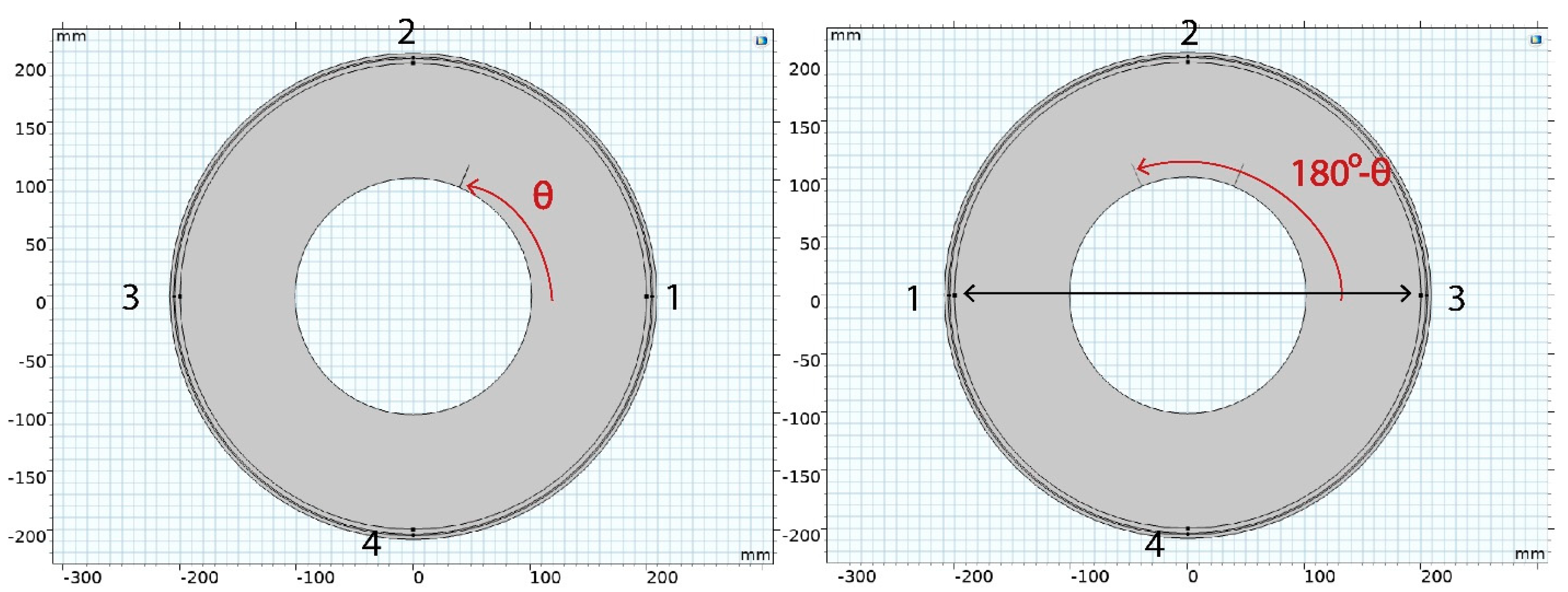
For the above-described simulations, the position of the defects is always selected using a set of random numbers that are uniformly distributed to the appropriate range. In the case of a single bore crack, the angular position is restricted for the simulations in the range of [0°, 90°]. Using the extracted values of the strain field in the exact point location of the four sensors, and based on the circular symmetry of the SRM geometry, we extended the dataset in the remaining three quarters of the cylinder. This was performed via mutual interchange of the location of the sensors, as shown in Figure 7. Particularly, provided a bore crack at a depth located in the first quarter of the cylinder, we can extract the strain values for a bore crack of an equal depth a located in the second quarter of the cylinder (angular position range: [90°, 180°]) by mutually interchanging the location of sensors 1 and 3. The corresponding position of the bore crack is given by the appropriate shift, [180°−θ], where θ is the angular position of the initial bore crack in the range of [0°, 90°]. Respectively, by mutually interchanging the location of strain sensors 2 and 4, we can result with a bore crack of the same depth located at the fourth quarter of the cylinder; i.e., in the range of [270°, 360°]. Finally, if we interchange the sensors in locations 2 and 3 while at the same time interchanging the location of sensors 1 and 4, we extract the sensors values as if the bore crack was located in the third quarter of the cylinder; i.e., in the range of [180°, 270°). Provided that the simulations are performed for 2000 cases of bore cracks located only in the first quarter, we followed this simple strategy to multiply the dataset by a factor of four while at the same time covering the entire cylinder. The same strategy is followed for the case of delamination. In the case of coexistent bore cracks and delamination, in the simulated cases, the angular position of the bore crack is restricted in the range of [0°, 90°], corresponding to the first quarter of the cylinder, while the relative angle between the two defects is a number randomly selected in the range of [0°, 360°). In this way, it is assured that the relative angular distance between the defects can take any value in the entire cylinder. This strategy results in multiplication of the data by a factor of 4. Therefore, the final dataset used for training and validating the developed neural network-based diagnostic system consists of 24,000 cases. Moreover, this approach was proven to be equivalent to the raw data production by FEA; i.e., the process was verified by comparing the results with the strain values in the particular positions of the strain sensors when the defect is initially located in the sifted angular position. The error is negligible, lower than 0.1 με, and it is attributed to the selected mesh size of the FEA. Thus, it could be further reduced through the application of a denser mesh.

3. Defect Diagnosis Using Machine Learning Techniques

3.1. Deep Neural Networks

Deep neural networks are a subcategory of machine learning techniques that can be employed to develop system diagnosis and structural health monitoring tools, provided the use of sensors readings. Deep fully connected neural networks are neural networks with multiple hidden layers between the input nodes and the output layer, which consist of fully connected (FC) layers. In FC layers, each neuron applies a linear transformation to the input vector through a weight matrix and a bias matrix. Thus, an FC layer consists of the weights and biases, along with the neurons, and it is used to connect the neurons between two different layers. In the FC layers, all the input nodes are connected to all the output nodes, meaning that a change in one input node affects all output nodes. In the following section, we present the two parts of the developed diagnostic tool, both consisting deep FC networks with the appropriate selection of the corresponding weights and bias initialization, suitable for the purposes of classification (first step of health state extraction), and regression (second step of defect extent prediction).

3.2. Classification of Health State Classes Using Deep Neural Networks

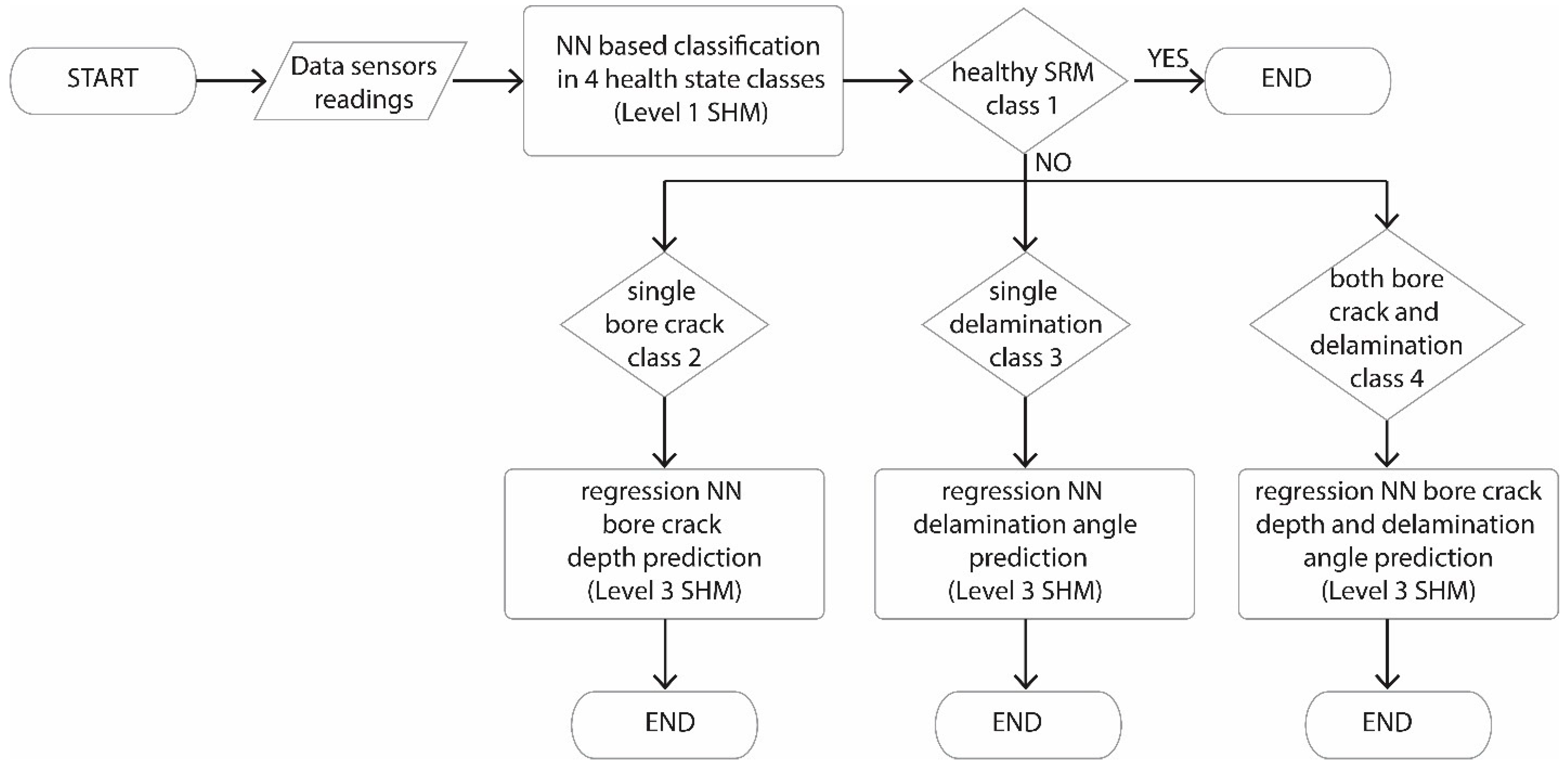
The first step of the diagnosis comprises the classification of the health state of the SRM (level I SHM) in one of the following classes: (a) healthy state in which the present flaw, either a bore crack or a delamination, is below the threshold limit, (b) damaged case with the presence of a single bore crack, (c) damaged case with the presence of a single delamination, and (d) damaged case with the presence of both a bore crack and a delamination. Figure 8 provides a high-level flowchart to illustrate the process of health state identification and defect detection. The neural network architecture is illustrated in Figure 9, while Table 2 provides a detailed description of all the layers participating in the network.
The selected architecture of the deep neural network contains 11 fully connected (FC) layers—denoted with the prefix ‘fc’—in which all input nodes of the layer are connected to all output nodes of this specific layer. Among the 11 FC (fc) layers, 10 layers are used in a sequential structure, followed by a rectified linear unit (ReLU) layer denoted with the prefix ‘ReLU’. The selected weights initializer is set to ‘orthogonal’, while the bias initializer is set to ‘narrow–normal’. The prefixes ‘add’ and ‘cat’ are used to denote addition and concatenation layers, which are both used to connect the main branch of the neural network with the two additional branches. All the developed NNs and corresponding data handling are performed in a MATLAB environment.
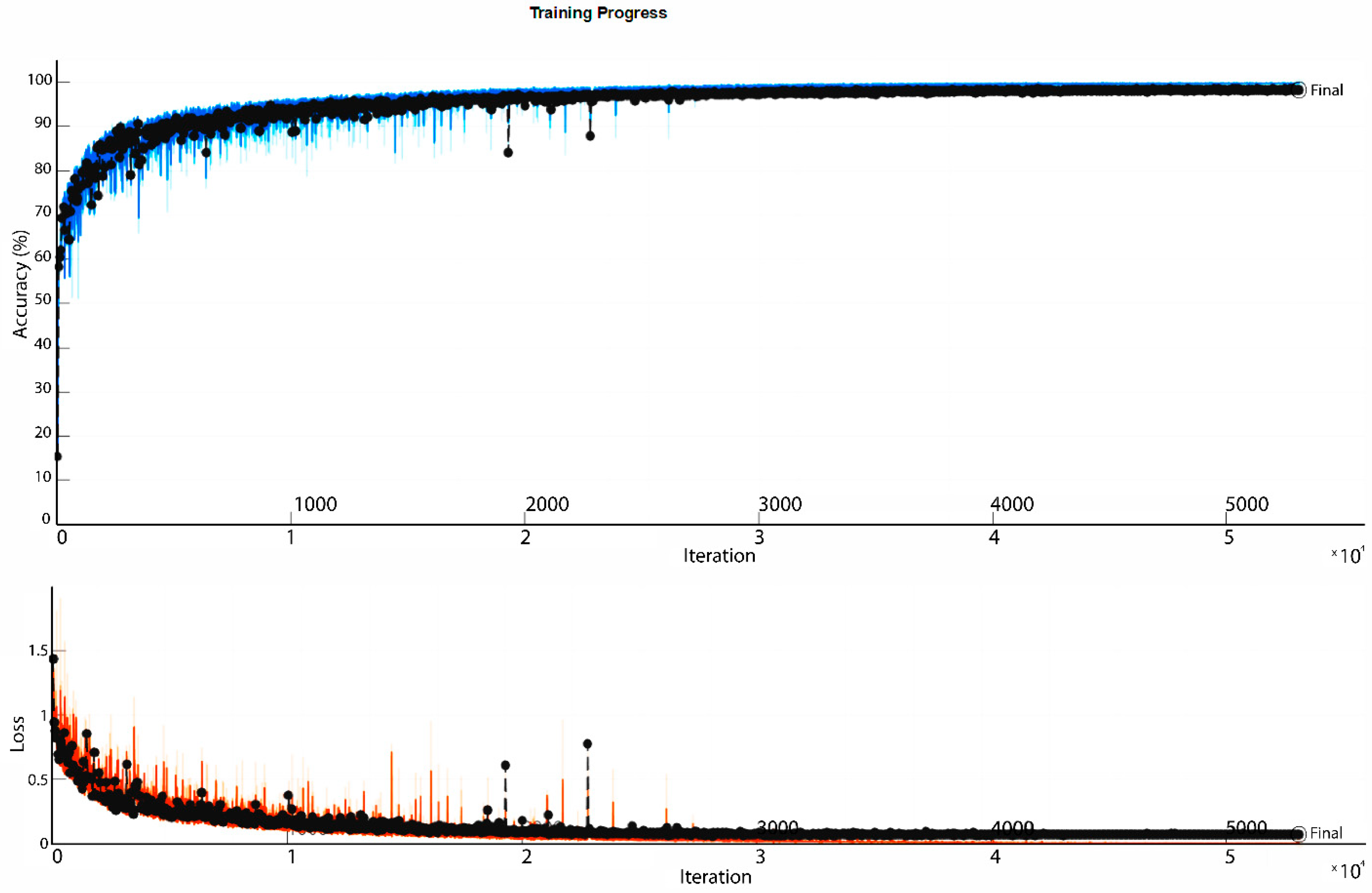
The parameters significantly affecting the training process are: (a) the selected optimizer algorithm, set to ADAM (adaptive movement estimation method), which is an extended version of stochastic gradient descent (SGD) that is particularly suitable for classification purposes, (b) the batch size, which is set to 2048, resulting in 10 iterations per epoch, provided the use of 90% of the total amount of available data for the training set and 10% of the remainder for the validation set. The training is performed using a ‘piecewise’ learning rate schedule, which means that the learning rate starting from an initial value of 0.001 drops with a factor of 1‰ every epoch during the entire training procedure. The maximum number of epochs is set to 10,000, with a validation patience of 500 epochs to avoid overfitting. Thus, the training is stopped after 5310 epochs, reaching a validation accuracy of 98.38%. The required training time does not exceed 41 min when running on a single Intel® Core i7-10750H CPU (16 Gb RAM) on a 64-bit operating system. The plots describing the accuracy increase and loss reduction during the entire training process are given in Figure 10, showing an adequate convergence after approximately 5000 iterations.
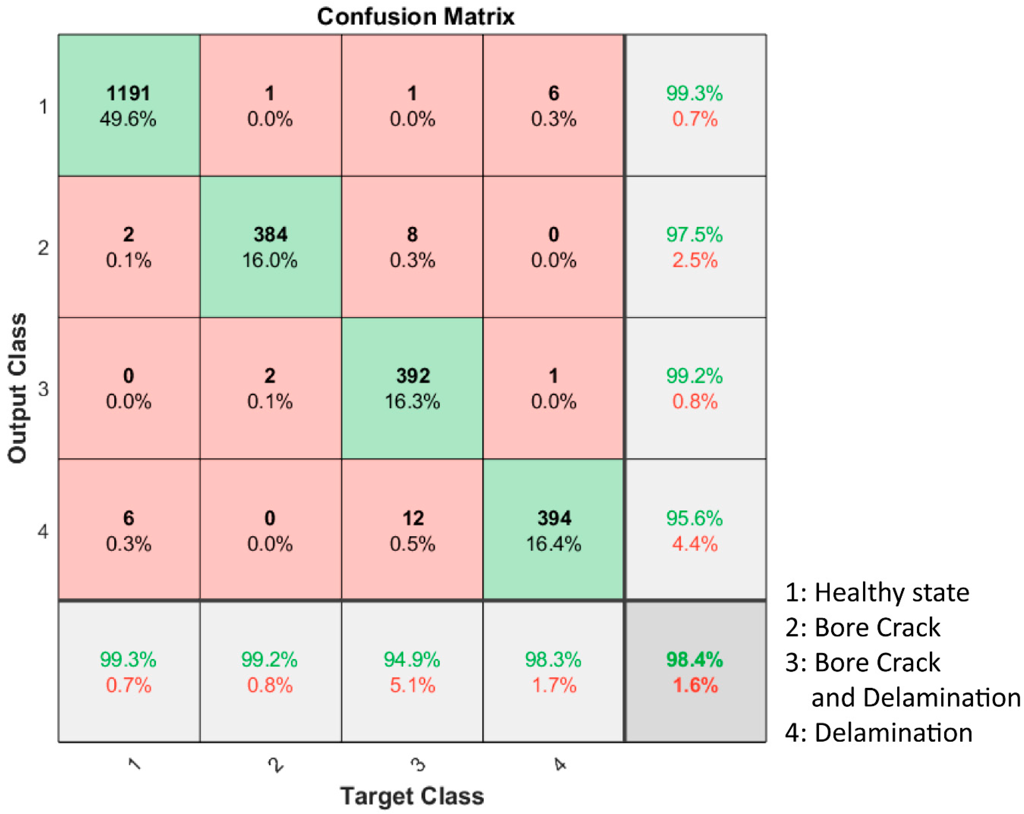
The validation accuracy is presented in Table 3 per class, along with the corresponding confusion matrix (Figure 11). In the confusion matrix, the numbers in each box represent the examined cases, with the percentage over the total sum of all examined cases given below the absolute number.
The last column of the confusion matrix gives the recall, defined as the ability of a model to find all the relevant cases within a data set, mathematically given by the following formula:
r e c a l l = T r u e   p o s i t i v e T r u e   p o s i t i v e + F a l s e   n e g a t i v e ,
The last line of the confusion matrix gives the precision of the model per class, defined as the ability of the classification model to identify only the relevant cases. It is described mathematically by the formula:
P r e c i s s i o n = T r u e   p o s i t i v e T r u e   p o s i t i v e + F a l s e   p o s i t i v e ,
It is proven that the false positive and false negative results are limited, with higher values given between the ‘bore crack and delamination’ class and the ‘delamination’ class. Twelve cases of ‘bore crack and delamination’ were falsely classified as ‘delamination’. Further analysis of these false results proved that these false classification cases mainly corresponded to rather small bore cracks (bore crack depths below 12 mm and ~75% of them below 5 mm) combined with a delamination.
The accuracy of the model is mathematically calculated as follows and it is proven to be remarkably high, reaching 98.38%:
a c c u r a c y = T r u e   p o s i t i v e + T r u e   n e g a t i v e T r u e   p o s i t i v e + T r u e   n e g a t i v e + F a l s e   p o s i t i v e + F a l s e   n e g a t i v e ,
We additionally provide the   f 1 score per class, which is a metric of how strong a classifier is. It is given as a harmonic mean between the two other provided metrics, precision and recall, per class:
f 1   s c o r e = 2 × P r e c i s i o n × R e c a l l P r e c i s i o n + R e c a l l ,

3.3. Defect Extent Prediction Using Regression Deep Networks

The second step of the SRM diagnosis comprises a regression network built using the same architecture for each one of the above three classes of damaged states of the SRM and trained individually for each case to accurately predict the extent of the defect. The structure of the neural network follows the basic principles of the deep networks’ architecture developed for classification in the previous step. The network contains a main branch with sequential use of FC layers and ReLU layers. These are combined with the raw strain sensors’ data and the output of a single FC layer, along with a ReLU activation layer, using a concatenation layer and an addition layer, respectively. The analytical description of the network architecture is depicted in Figure 12, with the participating parameters being given in Table 4.
In the case of the regression deep neural network, the weights initializer is set to ‘He’ for all FC layers. The He initialization is an initialization method used in NNs which takes into account the non-linearity of activation functions [29]. Additional batch normalization and dropout layers (20%) are used once in the entire neural network to reduce overfitting. The initial learning rate is set to 0.0005, again following a piecewise learning rate schedule with a 1‰ drop factor in every epoch. The batch size is set to a much lower value than the one in the classification due to the remarkably smaller dataset used to feed the neural network this time. The dataset for the regression network is 1/6 of the entire developed dataset, corresponding to one of the 3 cases/classes of the damaged state of the SRM. Thus, the batch size is set to 64, and the resulting number of iterations per epoch is 56. A validation patience strategy is again followed to avoid overfitting, with the corresponding parameter set to 100 epochs. Finally, the optimizer algorithm selected for the regression network is the root mean square propagation (RMSprop), which best fits regression networks, rather than the ADAM optimizer selected for the classification deep neural network. The developed network was trained individually for each case of the damaged state of the SRM; thus, all parameters related to the training process were analyzed separately for each case in the following analysis.

3.3.1. Bore Crack Prediction

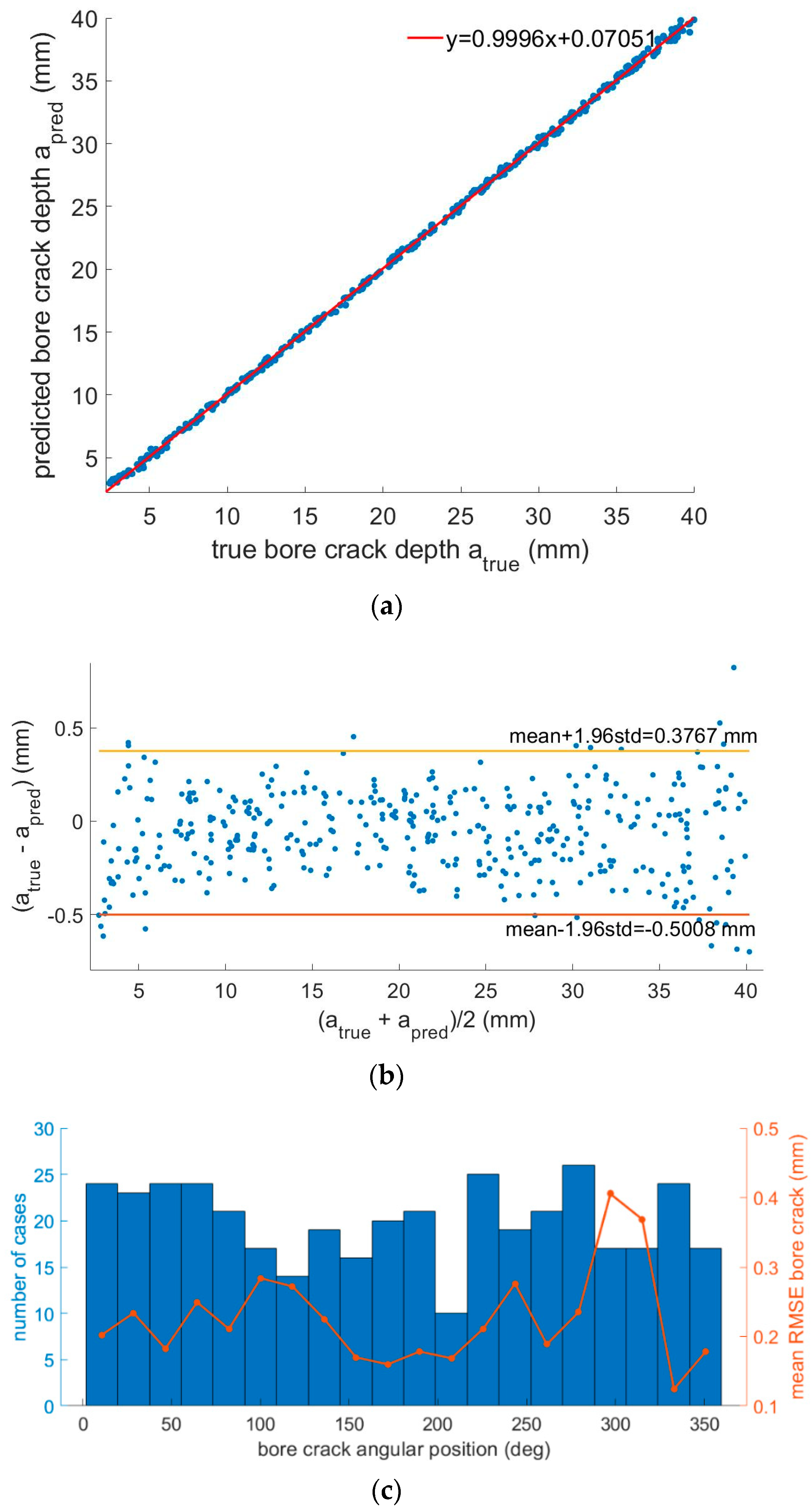
For the case of a single bore crack, the regression deep neural network is trained using 90% of the damaged cases containing a bore crack in the range of (2.2 mm, 40 mm]. The validation root mean square error (RMSE) is 0.2320 mm. A total of 428 epochs are needed to accomplish the entire training process, which corresponds to a time duration of 13 min and 50 s. In Figure 13a, the predicted values of the bore crack depth are given with respect to the true values. The fitted curve is y = p 1 · x + p 2 , with the coefficients being p 1 = 0.9996 (95% confidence bounds: (0.9976, 1.002)) and p 2 = 0.07051 (95% confidence bounds: (0.02222, 0.1188)). For the representation of the provided results, we opted for the additional use of Bland–Altman plots, giving the distribution of the error of prediction in the entire range of the targeted defect extent values to extract any dependency of the accuracy of the developed regression model on the bore crack depth. This type of plot demonstrates the error of prediction, defined as the difference a t r u e a p r e d i c t e d over the mean of the true and predicted values of the bore crack depth, ( a t r u e + a p r e d i c t e d ) / 2 . The corresponding Bland–Altman plot given in Figure 13b proves a negligible correlation between the prediction error and the depth of the bore crack. Finally, we present the distribution of the RMSE over the angular position of the bore cracks by dividing the entire angular position range (360°) into 20 bins.
The corresponding plot given in Figure 13c shows: (a) that the number of randomly selected validation cases is uniformly distributed in the entire circular SRM cross section, given by the number of cases per bin (left axis), and (b) that the distance from the sensors does not seem to affect the prediction accuracy in the selected range of bore crack depths corresponding to the damaged health state of the SRM.

3.3.2. Delamination Prediction

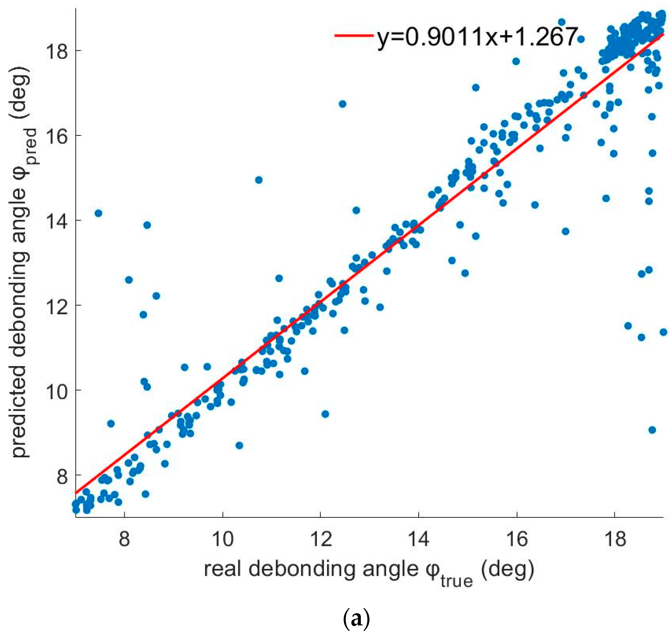
In the class of a damaged health state with a single delamination, the network is trained again using the same percentage of the available data (90%), which corresponds to 3600 cases. The remaining 400 cases are used for the validation of the network. The required time for training, provided that the use of validation patience is equal to 100 epochs, does not exceed 15 min, and the provided validation RMSE is 1.2897°. In Figure 14a, the predicted values of the delamination extent are given with respect to their true values in the validation dataset. The curve fitting the combination of the predicted and true data for the angle of delamination is y = p 1 · x + p 2 , with the coefficients being p 1 = 0.9011 (95% confidence bounds: (0.8696, 0.9325)) and p 2 = 1.267 (95% confidence bounds: (0.7968, 1.737)). The Bland–Altman plot corresponding to this case and provided in Figure 14b also proves a negligible dependence of the prediction error on the angular size of the debonded region for the specified range of (7°, 19°]. iIn other words, the developed model can predict a small or a large delaminated region with approximately the same accuracy. Finally, the plot in Figure 14c gives the distribution of the RMSE over the randomly selected angular position of the delamination for all cases participating in the validation dataset, as well as the distribution of the number of examined cases over the entire SRM circular cross section. The prediction error does not seem to be strongly affected by the position of the delamination with respect to the sensors’ positions, with the RMSE being held below 2° for most cases, apart from the bin (126°,144°], in which the mean RMSE reaches the highest value of approximately 4°. The plot also proves that the validation dataset comprises cases that are evenly distributed in the SRM circle and that there is no correlation between the number of cases per bin (left axis of the plot) and the mean RMSE of each bin (right axis of the plot).

3.3.3. Combined Cracks and Delamination Detection

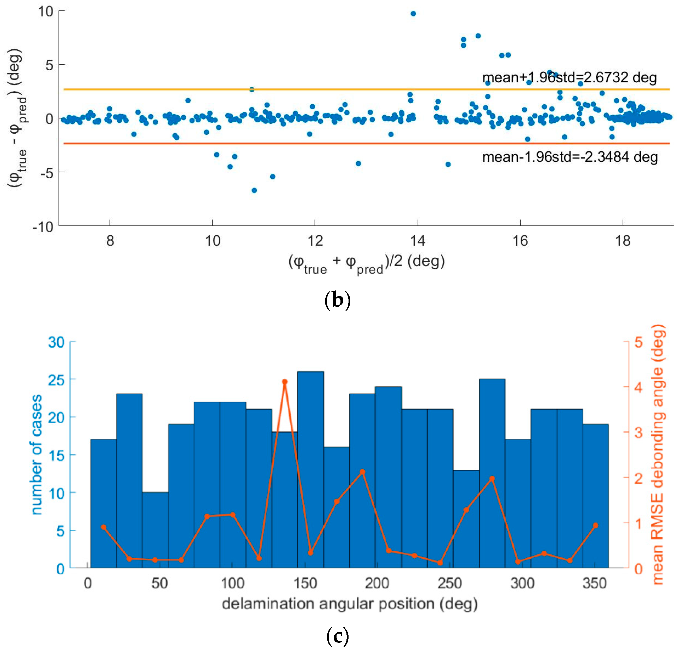
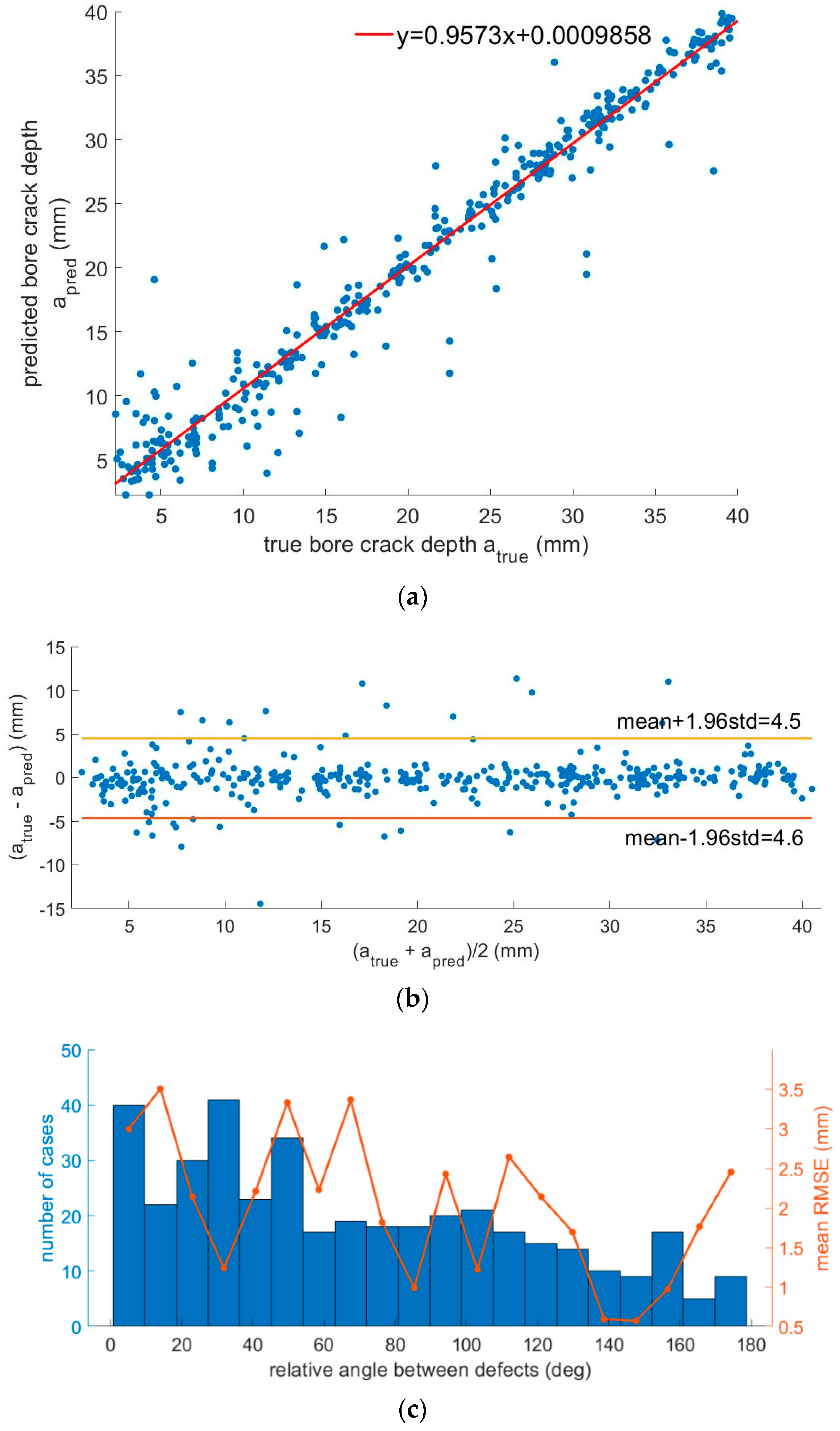
The class of the damaged state of the SRM that corresponds to the coexistence of a bore crack and a delamination is the most demanding, as two different values of the extent of the defect are to be predicted. The training process stops after 1000 epochs, with the required time reaching approximately 30 min. The provided RMSE for the case of the bore crack is 2.3 mm, and for the case of the delamination, it is 1.5678°. In Figure 15a and Figure 16a, we present the predicted values along with the true values of the bore crack depth and the delamination angle, respectively. The curve fitting the data in the predicted vs. true values plot for the bore crack is y = p 1 · x + p 2 , with the coefficients being p 1 = 0.9573 (95% confidence bounds: (0.9372, 0.9773)) and p 2 = 0.0009858 (95% confidence bounds: (0.000507, 0.001465)). The corresponding fitting curve process for the case of the delamination results in the curve y = p 1 · x + p 2 , with the coefficients being p 1 = 0.8028 (95% confidence bounds: (0.7647, 0.8409)) and p 2 = 2.612 (95% confidence bounds: (2.103, 3.122)). We also represent the corresponding Bland–Altman plots, revealing any dependency of the prediction accuracy on the extent of each defect in Figure 15 plot (b) and Figure 16 plot (b). Both Bland–Altman plots prove the negligible dependence of the prediction error on the size/extent of the defect. In this health state, we opted for presenting the variation in the RMSE with respect to the relative angle between the defects by dividing the entire range of the relative angle (180°) into 20 equally wide bins. The corresponding plots are given in Figure 15c and Figure 16c for the case of the bore crack and the delamination, respectively. It is proven that there is no correlation between the prediction error of the bore crack depth and the relative angle between the defects, with the mean RMSE per bin reaching a maximum value of approx. 3.5 mm. In the case of the delamination, the mean RMSE per bin is held below 3°; however, it reaches its maximum value for the most distant defects, corresponding to the bin (171°,180°]; i.e., the relative angle between them is approximately equal to 180°. Additionally, we observed an increased distribution of the number of cases participating in the validation dataset that belong to the bins with narrow angular distances between the two defects. This is expected to be the case for the training dataset, and it is attributed to the fact that the angular position of both defects is uniformly distributed in the entire circle.

4. Discussion and Future Perspectives

The presented results provided a systematic study on the investigation of the combined performance of both the health state classifications, particularly in predicting the types of defects that are present in the SRM and the defect extent prediction through the corresponding regression neural network. Previous research studies have reported on some of related issues [11], but none have opted for the combination of these steps, which can lead to a complete diagnosis of the SRM health state. Particularly, Liu et al. reported on the defect extent prediction error only for the case of a coexistent bore crack and delamination [11] using an architecture of deep convolutional neural networks (CNNs) similar to the one reported here. This architecture was able to predict the delamination angle and bore crack depth in the case of coexistent defects and provided the use of DBST sensors. In this work, we introduced a NN with fully connected layers instead of a CNN; the single use of four sensors readings instead of a temperature-dependent data series as the input given to the network; and the incorporation of cases of single defect prediction along with the case of combined cracks and delamination for accurate SRM diagnosis across a wider range of defects. Particularly, in the case of coexistent bore cracks and delamination, our findings are in full compliance with previous reported works [11], additionally providing a reduced prediction error as well as a broader range of defect extent detection.
The broadening of the defect extent range, with the inclusion of smaller defects, is attributed to the employment of optical fiber strain sensors that, due to their achievable resolution, are capable of detecting smaller defects compared to well-established DBST deformation sensors. Although very limited previous work is available on optical fiber integration in composite propellants, in principle, optical fibers provide the flexibility to be incorporated anywhere in the propellant at various geometries during the propellant casting process by providing suitable bonding and glueing process with specific primers [8]. However, further investigation is required depending on the fiber material (silica, polymers) and coating. In contrast, DBST sensors can be only embedded in SRMs through the metal casing in order to reach the upper layer of insulation. Therefore, optical fiber sensors are exposed to regions of larger deformations and higher variations of the strain field, which consequently leads to the detection of smaller defects. This is proven by the comparison of the calculated threshold between the healthy and the damaged state for both the bore crack case and the delamination case, which are both much smaller than previously targeted defects [11]. We opted for assuming the use of optical strain sensors profiting from their capacity to detect much smaller defects—both bore cracks and delamination—and the performance of the developed network is also evaluated in these cases. Furthermore, optical strain sensors based on Bragg gratings on optical fibers is a dynamic research area that provides continuously enhanced sensors in terms of functionality and resolution. FBGs can be concatenated in reasonably high numbers, enabling a multipoint quasi-distributed sensor operation via monitoring without deteriorating the mechanical properties of SRMs. This is accomplished through the seamless incorporation process of FBGs within the core of a fiber with a typical diameter of 125 μm or less. Furthermore, new advances have enabled the inscription of FBGs in polymer optical fibers of a higher elasticity than typical silica fibers, thus providing higher strain range capabilities [30,31]. Based on the presented results, we demonstrated the potential of neural networks combined with optical strain sensors to perform complete SRM health state diagnoses with a high accuracy and to identify the extent of the present defect.
Our approach is limited by the use of a dataset generated through simulations of the SRM behavior in specific thermal cycles due to a lack of real data recordings. There are several assumptions related to the simulated models that are made in favor of simplification and required time compensation. These assumptions impose the main restrictions of the applications of our work. Particularly, in our finite element models (FEMs), we assume homogeneous thermal change of the entire SRM body, and all materials are treated as linear elastic. We also excluded the temperature dependence of several material parameters such as the Young’s modulus to further simplify the simulation process and generate a large amount of data within a restricted time duration and a reduced computational capacity. We did not include any investigation of the material degradation that is frequent in real practice, reflecting material property changes that could result in different strain field distributions. All of above aspects are considered beyond the purposes of this work. They are treated separately in other previously published works by taking into account various material uncertainties [32], remaining open to further investigation in future works.
The present study is based on a stationary regime approach, considering only the thermal loading effect where the SRM model is subjected. Here, the transition from the initial curing and stress-free temperature of 71 °C, down to extreme conditions of −51 °C is considered. However, in realistic dynamic conditions, in addition to various environmental factors, vibrations could significantly affect the signal quality obtained by FBGs by introducing additional noise due to captured vibrations, mostly during the SRMs’ transportation or pre-operation stages. Although the detailed discussion of possible vibration issues is out of the scope of the present paper, efficient solutions for vibration noise elimination are easily identifiable. One solution could be the partial cancelation of noise due to vibrations by deploying an individual FBG sensor decoupled from the propellant material itself and the resulting stress and strain effects in order to monitor only the mechanical vibrations on the SRM casing. Feeding such individual vibration information into the machine learning (ML) algorithm could significantly improve the performance of such ML-based structural diagnosis in dynamic realistic environments with the presence of vibrations.
Additional factors that need to be further investigated concern the number of sensors per circumference that achieve optimum compensation between the cost and the accuracy of the developed diagnostic system. The neural networks developed for the presented approach were also evaluated in a preliminary study with the use of eight (8) sensors, giving no noticeable increase in the provided classification accuracy or further reduction in the RMS error in the case of the regression networks. Moreover, the use of eight sensors was related to the occurrence of overfitting earlier in the training process, resulting in a final classification accuracy of 97.17% and an RMSE of 4.1 mm in bore crack depth prediction and 2.9552° for the delamination angle in the most demanding case of coexisting defects. Thus, additional techniques for overfitting reduction, such as batch normalization and dropout [33], regularization [34], and likely the reduction of the batch size, should be employed to further investigate the ways to reach higher accuracies via the increase in available strain sensors. However, it is important to note that the existence of four sensors in the circumference of the SRM possibly imposes a reasonable limit, given that in practical real monitoring applications, the entire SRM length should be covered, thus leading to issues related to the cost of the sensors and the associated interrogation complexity with the increasing number of sensing points. Thus, most studies follow the same regime concerning the number of sensors [11,18]. However, the cost and interrogation complexity of using arrays of FBG sensors compared to multiple DBST sensors would be drastically lower. Optimal numbers of sensors in a 3D structure of the SRM as well as the optimal sensors placement issue [35] that inevitably emerges are subjects to being separately investigated in future studies.
The present study is a theoretical investigation on the applicability of FBGs in SRM structural diagnosis, and a detailed study on operational scenarios as the diagnostic approaches operated in the frame of condition-based maintenance (CBM) strategies was not included. These studies are still in an initial exploratory stage in the SRM industry. However, the monitoring of propellants in SRMs needs to take place during the propellants’ curing process at the manufacturing, storage, and transportation stages, as well as possibly during SRM loading before ignition and operation. During the curing process and storage, the environmental conditions change relatively slowly or remain mostly constant, respectively. Therefore, depending on the monitoring requirements, a sample rate for data acquisition could be one sample per hour, up to one sample per minute at most. During transportation and operation, the situation is significantly different for distinct application areas such as SRMs integrated in guided missiles for tactical applications or SRMs as boosters (SRBs) mainly for space exploration applications. SRM-based missiles can be loaded on aircrafts, thus leading to extreme temperature variations larger than 100 °C and also extreme accelerations >8 g during flights. For the monitoring of the impact of such fast-occurring environmental changes, a sample rate of >1 sample per second or even in the KHz range would be required. Additionally, continuous monitoring of SRBs in space applications could be required in order to confirm the structural integrity of propellants even just before the ignition stage. Widely commercially available FBG interrogators can provide sampling ratios of up to tens of KHz, which is perfectly adequate for the aforementioned applications.
The developed regression deep neural network was additionally evaluated for predicting the location of the defects present in each case. In this case, the position error was calculated, taking into account the circular geometry of the SRM cross section given by the following formula:
p o s i t i o n   e r r o r = ( 360 ° m o d Y v a l i d a t i o n Y p r e d i c i t o n ) 2 N ,
where Y v a l i d a t i o n represents the true values of the target angular position, Y p r e d i c t i o n represents the predicted values of this variable, and N is the total number of cases participating in the validation dataset. The provided RMSE was acceptable in the case of a single bore crack (RMSE 7.48°). It was severely increased in the case of a single delamination (RMSE 36.99°), while the network failed to accurately predict the position of the defects when more than one defect was present in the SRM, as the obtained RMSE was larger than 50° for both bore cracks and delamination in case of coexisting defects.

5. Conclusions

This work presented for the first time the theoretical design of a deep learning-based diagnosis system for SRMs by employing a scenario using fiber Bragg gratings-based strain sensors. The demonstrated performance exceeded the current capabilities of systems using traditional and widely employed DBST. More specifically, the use of efficient neural networks was introduced with fully connected layers, assuming a rather moderate strain resolution performance of 4 με, which is achievable using FBG-based strain sensors. This approach proves promising in providing accurate diagnosis of the SRM for the detection of defects and the extent of bore cracks and/or delamination by demonstrating an accuracy of more than 98% and predicting the extent of the defect with an error of 2.3 mm for the bore crack depth and 1.6° for the delamination angle in the worst case of coexistent defects. The higher prediction accuracy compared to previously published results, together with the unique characteristics of the optical fiber-based sensors, suggests a viable direction for a robust and reliable physical implementation for SHM systems in SRMs via the use of FBGs.
Focusing on the use of optical FBG strain sensors as a new approach as strain sensors for SRM monitoring, the following advantages can be identified and summarized:
  • The hoop strain monitoring approach is proven to be more efficient compared to radial stress monitoring, as the change range ratio to the FBG strain resolution for a given defect is at least one order of magnitude larger than the corresponding ratio in current DBST solutions.
  • Cracks or delamination defects induce a much wider spatial effect on hoop strain compared to the corresponding effect on axial/radial stress, thus easing their detection by strain point sensors compared to DBST/stress point sensors.
  • Optical fibers provide the flexibility to be integrated in various geometries and at optimal positions in the propellant grain even close to the bore, in contrast to DBSTs, which can be placed only through the metal casing and close to the insulation area, thus providing better sensitivity.
  • Optical FBG strain sensors can be seamlessly integrated in SRMs, not affecting their handling, transportation, storage, or operation, in contrast to DBSTs, where such external sensors are placed in the metal casing with external electric wiring, making monitoring difficult during the SRM life cycle.
  • FBG strain sensors are passive and can provide continuous monitoring of SRMs due to their seamless integration capability inside the SRM body, in contrast to DBSTs, which are placed outside the metal casing, limiting their monitoring to only controllable laboratory conditions.
  • As SRMs can experience drastic environmental changes during transportation, storage, or operation, in terms of acceleration, temperature, and humidity, their structural integrity needs to be continuously monitored. However, an event of a sudden defect under extreme conditions can be securely logged and registered as a permanent Bragg Grating wavelength shift even if the continuous real-time monitoring was offline. This is in contrast to DBSTs, where electric power is required to interrogate the SRM and register a measurable defect.
  • FBGs and optical solutions provide unique characteristics such as intrinsically electric safety and immunity to electromagnetic interference, which are crucial in a highly explosive propellant material system.
  • The optical fiber monitoring approach provides the capability of easy interconnection to the FBG interrogation unit using a single optical fiber output, also providing the capability of remote monitoring through a fiber optic channel or network.
Overall, it is anticipated that fiber optic strain sensors will become the preferred solution to SRM continuous monitoring, thus providing real-time data for feeding machine learning-based diagnostic approaches operating in the framework of modern condition-based maintenance (CBM) strategies.

Author Contributions

Conceptualization, C.R.; methodology, G.K. and C.R.; validation, G.K., C.R. and K.N.A.; formal analysis, G.K. and C.R.; investigation, C.R., G.K., K.N.A., N.C. and G.M.; resources, C.R. and K.N.A.; writing—original draft preparation, G.K.; writing—review and editing, G.K., C.R., K.N.A. and G.M.; visualization, G.K.; supervision, C.R.; project administration, C.R.; funding acquisition, C.R. All authors have read and agreed to the published version of the manuscript.

Funding

This research was funded by Bayern Chemie GmbH Germany in the framework of the collaborative Project RocketSens (Contract No: 2018-0720-1). Partial support was also received from the Hellenic Foundation for Research and Innovation (H.F.R.I.) under the “First Call for H.F.R.I. Research Projects to support Faculty members and Researchers and the procurement of high-cost research equipment grant” (Project Number: HFRI-FM17-640, InPhoQuC).

Institutional Review Board Statement

Not applicable.

Informed Consent Statement

Not applicable.

Data Availability Statement

The original contributions presented in this study are included in the article. Further inquiries can be directed to the corresponding author.

Acknowledgments

The authors are grateful to Ludwig Eineder of Bayern-Chemie GmbH (MBDA Germany) for his useful discussions and for providing technical insights regarding strain and stress sensing in SRMs.

Conflicts of Interest

Author Günter Mußbach was employed by the company Bayern-Chemie GmbH (MBDA Germany). The remaining authors declare that the research was conducted in the absence of any commercial or financial relationships that could be construed as a potential conflict of interest.

References

  1. Dhital, D.; Lee, J.R.; Farrar, C.; Mascarenas, D. A Review of Flaws And Damage in Space Launch Vehicles: Motors and Engines. J. Intell. Mater. Syst. Struct. 2014, 25, 524–540. [Google Scholar] [CrossRef]
  2. McDonald, A.J. Solid Rocket Motor Failure. Encycl. Aerosp. Eng. 2010, 2, 1123–1129. [Google Scholar]
  3. Tussiwand, G.S.; Saouma, V.E.; Terzenbach, R.; de Luca, L.T. Fracture Mechanics of Composite Solid Rocket Propellant Grains: Material testing. J. Propuls. Power 2009, 25, 60–73. [Google Scholar] [CrossRef]
  4. Tussiwand, G.S.; Eineder, L.; Mussbach, G.; Bohn, M.A. Non-Destructive Ageing State Determination of Solid Rocket Motors Charges. In Proceedings of the 8th European Workshop on Structural Health Monitoring EWSHM, Bilbao, Spain, 5–8 July 2016. [Google Scholar]
  5. Sankar, R.A.; Anees, P.; Kumar, A.; Sriram, B.T. Structural Health Monitoring of Solid Propellant Using Embedded PVDF Sensor. In Proceedings of the International Conference on Power, Institute of Electrical and Electronics Engineers, New York, NY, USA, 18–20 January 2018. [Google Scholar] [CrossRef]
  6. Lopatin, C.M. Method for Measuring the Health of Solid Rocket Propellant Using an Embedded Sensor. U.S. Patent US7652488B1, 26 January 2010. [Google Scholar]
  7. Le, A.Q.; Sun, L.Z.; Miller, T.C. Detectability of Delaminations in Solid Rocket Motors with Embedded Stress Sensors. J. Propuls. Power 2013, 29, 299–304. [Google Scholar] [CrossRef]
  8. Riziotis, C.; Eineder, L.; Bancallari, L.; Tussiwand, G. Fiber Optic Architectures for Strain Monitoring of Solid Rocket Motors’ Propellant. Sens. Lett. 2013, 11, 1403–1407. [Google Scholar] [CrossRef]
  9. Mußbach, G.; Tussiwand, G.; Buswell, J. Assessing the Ageing-State of Solid Propellant Grains in Case-Bonded Rocket Motors by Measuring Bondline Stresses. In Proceedings of the Energetic Materials. Synthesis, Characterization, Processing. Fraunhofer-Institut für Chemische Technologie (43rd International Annual Conference), Karlsruhe, Germany, 26–29 June 2012. [Google Scholar]
  10. Xiao, H.-Y.; Gao, F. Fault Diagnosis of Solid Rocket Motor Based on Fuzzy Neural Network. In Proceedings of the 2012 International Conference on Electronics, Communications and Control, Yichang, China, 16–18 October 2012. [Google Scholar]
  11. Liu, D.; Sun, L.; Miller, T.C. Defect Diagnosis in Solid Rocket Motors Using Sensors and Deep Learning Networks. AIAA J. 2021, 59, 276–281. [Google Scholar] [CrossRef]
  12. Hoffmann, L.F.S.; Bizarria, F.C.P.; Bizarria, J.W.P. Detection of Liner Surface Defects in Solid Rocket Motors Using Multilayer Perceptron Neural Networks. Polym. Test. 2020, 88, 106559. [Google Scholar] [CrossRef]
  13. Dai, J.; Li, T.; Xuan, Z.; Feng, Z. Automated Defect Analysis System for Industrial Computerized Tomography Images of Solid Rocket Motor Grains Based on YOLO-V4 Model. Electronics 2022, 11, 3215. [Google Scholar] [CrossRef]
  14. Anhduong, A.; Le, Q.; Sun, L.Z.; Miller, T.C. Health Monitoring and Diagnosis of Solid Rocket Motors with Bore Cracks. J. Aerosp. Eng. 2016, 29, 04015058. [Google Scholar]
  15. Ramakrishnan, M.; Rajan, G.; Semenova, Y.; Farrell, G. Overview of Fiber Optic Sensor Technologies for Strain/Temperature Sensing Applications in Composite Materials. Sensors 2016, 16, 99. [Google Scholar] [CrossRef]
  16. Konstantaki, M.; Violakis, G.; Pappas, G.; Geernaert, T.; Korakas, N.; Tiriakidis, N.; Tiriakidi, T.; Tiriakidis, K.; Thienpont, H.; Berghmans, F.; et al. Monitoring of Torque Induced Strain in Composite Shafts with Embedded and Surface-Mounted Optical Fiber Bragg Gratings. Sensors 2021, 21, 2403. [Google Scholar] [CrossRef] [PubMed]
  17. Filograno, M.L.; Piniotis, G.; Gikas, V.; Papavasileiou, V.; Gantes, C.; Kandyla, M.; Riziotis, C. Comparative Assessment and Experimental Validation of a Prototype Phase-Optical Time-Domain Reflectometer for Distributed Structural Health Monitoring. J. Sens. 2022, 2022, 6856784. [Google Scholar] [CrossRef]
  18. Zhang, L.; Chang, X.-L.; Zhang, Y.-H.; Chen, X.-D.; Zhang, Q. On-Line Monitoring of SRM Grain Structure Based on Embedded FBG Sensor. In Proceedings of the 7th International Conference on Power Science and Engineering, EDP Sciences, Vienna, Austria, 19–21 November 2019. [Google Scholar] [CrossRef]
  19. Lopatin, C.; Grinstein, D. Active Sensing for Monitoring the Properties of Solid Rocket Motor Propellant Grains. Propellants Explos. Pyrotech. 2015, 40, 295–302. [Google Scholar] [CrossRef]
  20. Zhang, L.; Chang, X.; Zhang, Y.; Liu, W. Response of FBG Sensors Embedded in SRM Interface of Combustor when Subjected to Tri-Axial Normal Loadings. IEICE Electron. Express 2017, 14, 20170657. [Google Scholar]
  21. Korompili, G.; Mußbach, G.; Riziotis, C. Structural Health Monitoring of Solid Rocket Motors: From Destructive Testing to Perspectives of Photonic-Based Sensing. Instruments 2024, 8, 16. [Google Scholar] [CrossRef]
  22. Riziotis, C.; Vasilakos, A. Computational Intelligence in Photonics Technology and Optical Networks: A Survey and Future Perspectives. Inf. Sci. 2007, 177, 5292–5315. [Google Scholar] [CrossRef]
  23. Farrar, C.; Worden, K. Structural Health Monitoring: A Machine Learning Perspective; John Wiley & Sons, Ltd.: Hoboken, NJ, USA, 2013. [Google Scholar]
  24. Mieloszyk, M.; Krawczuk, M.; Skarbek, L.; Ostachowicz, W. An Application of Neural Network for Structural Health Monitoring of an Adaptive Wing with an Array of FBG Sensors. In Journal of Physics: Conference Series, 9th International Conference on Damage Assessment of Structures (DAMAS 2011), St Anne’s College, University of Oxford, 11–13 July 2011; IOP Publishing: Bristol, UK. [CrossRef]
  25. Kahandawa, G.C.; Epaarachchi, J.; Wang, H.; Canning, J.; Lau, K. Extraction and Processing of Real Time Strain of Embedded FBG Sensors Using a Fixed Filter FBG Circuit and an Artificial Neural Network. Measurement 2013, 46, 4045–4051. [Google Scholar] [CrossRef]
  26. Sundaram, R.; Kamath, G.M.; Gupta, N.; Rao, M.S. Structural Health Monitoring of co-Cured Composite Structures Using FBG Sensors. In Proceedings of the Smart Structures and Materials 2005: SPIE Smart Structures and Materials + Nondestructive Evaluation and Health Monitoring, San Diego, CA, USA, 17 May 2005. [Google Scholar] [CrossRef]
  27. Wang, D.; Zhang, W. Damage Detection Combining Principal Component Analysis and Deep Convolutional Neural Network with Dynamic Response from FBG Arrays. J. Civ. Struct. Health Monit. 2023, 13, 101–115. [Google Scholar] [CrossRef]
  28. He, Y.W.M.; Ramakrishnan, K.R.; Zhang, Z. A Comparison of Machine Learning Algorithms for Assessment of Delamination in Fiber-Reinforced Polymer Composite Beams. Struct. Health Monit. 2021, 20, 1997–2012. [Google Scholar] [CrossRef]
  29. Kaiming, H.; Xiangyu, Z.; Shaoqing, R.; Jian, S. Delving Deep into Rectifiers: Surpassing Human-Level Performance on ImageNet Classification. arXiv 2015, arXiv:1502.01852v1. [Google Scholar] [CrossRef]
  30. Lacraz, A.; Polis, M.; Theodosiou, A.; Koutsides, C.; Kalli, K. Femtosecond Laser Inscribed Bragg Gratings in Low Loss CYTOP Polymer Optical Fiber. IEEE Photonics Technol. Lett. 2015, 27, 693–696. [Google Scholar] [CrossRef]
  31. Leal-Junior, A.G.; Theodosiou, A.; Díaz, C.R.; Marques, C.; Pontes, M.J.; Kalli, K.; Frizera, A. Simultaneous Measurement of Axial Strain, Bending and Torsion With a Single Fiber Bragg Grating in CYTOP Fiber. J. Light. Technol. 2019, 37, 971–980. [Google Scholar] [CrossRef]
  32. Cholevas, N.; Anyfantis, K.N.; Mußbach, G.; Korompili, G.; Riziotis, C. Crack Identification in Solid Rocket Motors Through the Neyman–Pearson Detection Theory. AIAA J. 2023, 61, 2241–2254. [Google Scholar] [CrossRef]
  33. Srivastava, N.; Hinton, G.; Krizhevsky, A.; Sutskever, I.; Salakhutdinov, R. Dropout: A Simple Way to Prevent Neural Networks from Overfitting. J. Mach. Learn. Res. 2014, 15, 1929–1958. [Google Scholar]
  34. Nusrat, I.; Jang, S.-B. A Comparison of Regularization Techniques in Deep Neural Networks. Symmetry 2018, 10, 648. [Google Scholar] [CrossRef]
  35. Liangou, T.; Katsoudas, A.; Silionis, N.; Anyfantis, K. Statistical Pattern Recognition for Optimal Sensor Placement in Damage Detection Applications. In European Workshop on Structural Health Monitoring; Rizzo, P., Milazzo, A., Eds.; EWSHM; Springer International Publishing: Cham, Switzerland, 2022. [Google Scholar]
Figure 1. (a) Schematic of a typical SRM illustrating the main components. (b) Figure of SRMs with embedded DBST sensors on the casing, together with the external electric wiring.
Photonics 11 00799 g001
Figure 2. Plan view/cross section of the SRM for 2D analysis, together with a simplified explanatory schematic of the SRM layers (inset).
Photonics 11 00799 g002
Figure 3. (A) Solid rocket motor geometry design, along with a bore crack and a delamination. (B) The strain field distribution and the simulated deformation of the grain in the region close to (Ba) the bore crack and (Bb) the delamination. (C) The mesh close to the delamination (Ca) and the bore crack (Cb).
Photonics 11 00799 g003
Figure 4. (a) Residual hoop strain field distribution across the SRM circumference, extracted from a simulation of a circle inside the grain, with a distance of 3 mm from the propellant–insulation circular interface for 3 typical bore cracks with depths of 5 mm, 10 mm, and 20 mm located at 45°. (b) Residual radial stress field distribution across the SRM circumference, extracted from a simulation of a circle located in the middle of the insulation layer for the same bore cracks. (c) Comparison of the strain and stress field variations produced by the same defects (bore cracks of 5 mm, 10 mm, and 20 mm located at 45°) measured at the same radial distance in the middle of the insulation layer.
Photonics 11 00799 g004
Figure 5. (a) Stress field distribution produced by 3 delamination cases of 2°, 4°, and 8° in the circumference of the SRM in the middle of the insulation layer, where DBST sensors are designed to be placed. (b) Corresponding strain field distribution produced by the same delamination cases in the grain, 3 mm away from the insulation–propellant interface, which is the assumed location of the optical-based strain sensors.
Photonics 11 00799 g005
Figure 6. Strain field across the circular path of interest for different bore crack depths (Aa) and delamination (Ba) located at 45° (worst-case scenario). Zoomed regions for each of the above cases, for the bore crack (Ab), and for the delamination (Bb).
Photonics 11 00799 g006
Figure 7. Description of the followed strategy of mutual interchange of sensor locations for dataset multiplication and coverage of all possible angular positions of the bore crack or delamination. In the case illustrated here, a bore crack depth initially located at an angle of θ in the range of [0°, 90°] is transferred in the second quarter of the cylinder by mutually interchanging the location of sensors 1 and 3.
Photonics 11 00799 g007
Figure 8. Flow chart depicting the 2 steps of SHM diagnosis: step 1 (Level 1 SHM), providing the classification in the four (4) classes of health state, and step 2 (Level 3 SHM), providing the quantification of defects in each of the 3 damaged classes.
Photonics 11 00799 g008
Figure 9. Architecture of the developed classification layer.
Photonics 11 00799 g009
Figure 10. Accuracy and loss during the entire training process for the classifier corresponding to the prediction of the health state of the SRM. Blue and red lines indicate the training accuracy and loss respectively in a batch level, while black dots indicate the corresponding values at the end of each iteration.
Photonics 11 00799 g010
Figure 11. Confusion matrix based on the dataset used to validate the developed deep neural network. True indications appear in green color and false indications appear in red color. The same color rule applies in the boxes.
Photonics 11 00799 g011
Figure 12. The architecture of the regression deep neural network developed for the prediction of the present defect in each of the damaged health state cases/classes.
Photonics 11 00799 g012
Figure 13. Validation results of the regression deep neural network trained with damaged health state cases containing a single bore crack with a depth in the range of (2.2 mm, 40 mm]. (a) Plot of the predicted bore crack depth with respect to the real values of the bore crack depth along with the fitting curve. (b) Bland–Altman plot of the same validation data. (c) Plot of the RMSE (right axis) with respect to the angular position of the bore crack, separated into 20 bins.
Photonics 11 00799 g013
Figure 14. Validation results of the regression deep neural network trained using damaged health state cases containing a single delamination with an angular size in the range of (7°, 19°]. (a) Plot of the predicted delamination angle with respect to the real values of the delamination angle along with the fitting curve. (b) Bland–Altman plot of the same validation data. (c) Plot of the RMSE (right axis) with respect to the angular position of the delamination, separated into 20 bins.
Photonics 11 00799 g014aPhotonics 11 00799 g014b
Figure 15. Validation results of the regression deep NN trained with damaged state cases containing both a bore crack and a delamination, particularly related to the prediction of the bore crack defect. (a) The predicted bore crack depth with respect to its real value, along with the fitting curve. (b) Bland–Altman plot of the same validation data; (c) Plot of the RMSE (right axis) and the number of cases (left axis) with respect to the relative angle between the coexisting defects, separated into 20 bins.
Photonics 11 00799 g015
Figure 16. Validation results of the regression deep NN trained with damaged state cases containing both a bore crack and a delamination, particularly related to the prediction of the delamination. (a) The predicted delamination angle with respect to its real values, along with the fitting curve. (b) Bland–Altman plot of the same validation data. (c) Plot of the RMSE (right axis) and the number of cases (left axis) with respect to the relative angle between the coexisting defects, separated into 20 bins.
Photonics 11 00799 g016
Table 1. Material and geometry design parameters used in the simulations.
Material Domains
Material PropertiesPropellantInsulationCasing
Young’s modulus14.2 MPa33.5 MPa55.9 GPa
Coefficient of thermal expansion9.56 × 10−5 1/K8.75 × 10−5 1/K2.16 × 10−6 1/K
Poisson’s ratio0.4990.4990.3
Inner radius101.6 mm203.2 mm205.74 mm
Outer radius203.2 mm205.74 mm208.915 mm
Table 2. Classification network analysis parameters.
NameTypeActivationsLearnablesTotal Learnables
1InFeature input4-0
2fc1Fully connected layer 1024Weights 1024 × 4
Bias 1024 × 1
5120
3relu1ReLU1024-0
4fc2Fully connected layer1024Weights 1024 × 1024
Bias 1024 × 1
1,049,600
5relu2ReLU1024-0
6fc3Fully connected layer1024Weights 1024 × 1024
Bias 1024 × 1
1,049,600
7relu3ReLU1024-0
8fc4Fully connected layer512Weights 512 × 1024
Bias 512 × 1
5,248,000
9relu4ReLU512-0
10fc5Fully connected layer256Weights 256 × 512
Bias 256 × 1
131,328
11relu5ReLU256-0
12fc6Fully connected layer128Weights 128 × 256
Bias 128 × 1
32,896
13relu6ReLU128-0
14fc7Fully Connected Layer64Weights 64 × 128
Bias 64 × 1
8256
15relu7ReLU64-0
16fc11Fully connected layer64Weights 64 × 4
Bias 64 × 1
320
17relu10ReLU64-0
18add1Addition layer64-0
19fc8Fully connected layer32Weights 32 × 64
Bias 32 × 1
2080
20relu8ReLU32-0
21fc9Fully connected layer16Weights 16 × 32
Bias 16 × 1
528
22relu9ReLU16-0
23cat1Concatenation layer20-0
24fc10Fully connected layer4Weights 4 × 20
Bias 4 × 1
84
25sm1Softmax4-0
26cl Classification layer--0
Table 3. Validation accuracy factors per health state class provided by the developed deep neural network.
Healthy StateBore CrackBore Crack and DelaminationDelamination
Accuracy0.9838
Precision0.99330.99220.94920.9825
Recall0.99330.97460.99240.9563
f1 score0.99330.98340.99030.9692
Table 4. Regression network analysis parameters.
NameTypeActivationsLearnablesTotal Learnables
1inFeature input4-0
2fc1Fully connected layer1024Weights 1024 × 4
Bias 1024 × 1
5120
3relu1ReLU1024-0
4fc2Fully connected layer1024Weights 1024 × 1024
Bias 1024 × 1
1,049,600
5relu2ReLU1024-0
6fc3Fully connected layer1024Weights 1024 × 1024
Bias 1024 × 1
1,049,600
7relu3ReLU1024-0
8fc4Fully connected layer512Weights 512 × 1024
Bias 512 × 1
5,248,000
9relu4ReLU512-0
10fc5Fully connected layer256Weights 256 × 512
Bias 256 × 1
131,328
11bnBatch normalization layer256Offset 256 × 1
Scale 256 × 1
512
12relu5ReLU256-0
13dp5Dropout256-0
14fc6Fully connected layer32Weights 32 × 256
Bias 32 × 1
8224
15relu6ReLU32-0
16fc9Fully connected layer4Weights 32 × 4
Bias 32 × 1
160
17relu9ReLU32-0
18add1Addition layer32-0
19fc7Fully connected layer16Weights 16 × 32
Bias 16 × 1
528
20relu7ReLU16-0
21cat1Concatenation layer20-0
22fc8Fully connected layer1 or 2Weights 1 or 2 × 20
Bias 1 or 2 × 1
42
23relu8ReLU1 or 2-0
24outputRegression layer--0
Disclaimer/Publisher’s Note: The statements, opinions and data contained in all publications are solely those of the individual author(s) and contributor(s) and not of MDPI and/or the editor(s). MDPI and/or the editor(s) disclaim responsibility for any injury to people or property resulting from any ideas, methods, instructions or products referred to in the content.