Article

Adaptive Flow Timeout Management in Software-Defined Optical Networks

Institute of Telecommunications, Faculty of Computer Science, Electronics and Telecommunications, AGH University of Krakow, Al. A. Mickiewicza 30, 30-059 Krakow, Poland
*
Author to whom correspondence should be addressed.
Photonics 2024, 11(7), 595; https://doi.org/10.3390/photonics11070595
Submission received: 28 April 2024 / Revised: 17 June 2024 / Accepted: 19 June 2024 / Published: 26 June 2024

Abstract

:
Current trends in network traffic management rely on the efficient control of individual flows. Software-defined networking popularized this notion. Per-flow management is perfectly viable in standard IP networks, in which packet processing is in the electric domain. However, optical networks provide more restrictions and constraints making per-flow traffic management difficult. One of the most important challenges is to reduce the concurrent number of flows present in the flow tables to make the switching process quicker. In this paper, we propose a mechanism to manage flow timeout values that uses idle timeout and hard timeout parameters. To calculate the appropriate values of the parameters, the mechanism analyzes the packet inter-arrival times. The algorithm also takes into account the current occupancy of the flow table.

1. Introduction

Software-defined networking has gained a lot of attention in recent years, as it provides flexibility and fosters easier and faster network innovation. SDNs separate the data transmission layer from the control layer. The control layer, which is the responsibility of the central controller, is fully programmable, meaning that network devices allow packets to be transmitted according to rules defined by the SDN controller. Communication between the controller and network devices requires rules to enable the connection. One of the most popular solutions in this area is the OpenFlow protocol.
Although SDN, as a concept, was originally proposed for standard IP networks where packet processing is performed in the electrical domain, several approaches to using SDNs in the optical domain have also been proposed. In [1], the authors demonstrate the architecture of software-defined optical networks (SDONs). They show that the SDON concept proves to be more efficient and leads to making the networks flexible and programmable. Similarly, in articles [2,3,4,5], the authors highlight the importance of the SDN concept in controlling the optical part of the backbone network. The authors of [6] show that the OpenFlow protocol has the potential to be extended towards core optical networks. They experimentally demonstrate the integration of OpenFlow and GMPLS control planes. The proposed overlay model extends the functionality of a typical OpenFlow controller to interface with the GMPLS control plane.
Per-flow management, in general, is perfectly viable in standard IP networks, in which packet processing is in the electric domain. However, optical networks provide more restrictions and constraints, making per-flow traffic management difficult. One of the most important challenges is to reduce the concurrent number of flows present in the flow tables to make the switching process quicker. In this paper, we propose a mechanism to manage flow timeout values that uses idle timeout and hard timeout parameters. To calculate the appropriate values of the parameters, the mechanism analyzes the packet inter-arrival times and the current occupancy of the flow table.
The goal of our mechanism is to expedite packet processing times in software-defined optical networks. Upon receiving a packet, an SDON switch must find a corresponding entry in its flow table to read instructions related to packet handling. Our mechanism efficiently reduces the number of flows that occupy flow tables. This provides two advantages: (1) optical packet switching devices can be constructed with smaller table sizes, which often makes them faster and cheaper, and (2) the flow table occupancy is lower on average, which allows the user to find a particular entry quicker.
Before we investigate the state-of-the-art literature, an introduction to flow processing in SDN is necessary. An OpenFlow-compliant switch is based on the concept of a flow table, in which flows are stored. If traffic arriving at the switch matches a flow in the table, it is handled by the device according to the rules stored in the table. Otherwise, the node routes the request to the central controller. The controller can add, update, and delete flow table entries, either reactively in response to packets or proactively by installing a rule before any packet arrives at the switch. Flows installed in the flow table, thanks to the instructions they contain, allow the switch to decide what to do with a received packet. Flows can be written into the flow table permanently or temporarily. Flows entered permanently are deleted only at the controller’s command. Flows entered temporarily (the default mode) are deleted when the flow lifetime is exceeded. There are two parameters that determine the flow lifetime:
  • Hard timeout: the flow will be deleted after a set number of seconds, regardless of its activity;
  • Idle timeout: the flow will be deleted after a set number of seconds of inactivity.
Flow array entries require memory resources. Flow tables are commonly implemented in ternary content-addressable memory (TCAM). Due to the huge amount of traffic occurring in networks and the need to quickly decide where to direct such traffic, high performance of these memories is needed. TCAM allows very fast browsing of the flow entries stored in it, but this is associated with a high production cost and high power consumption [7]. Optimizing the size of the required arrays is an important research problem. The problem is especially important for optical networks, which operate at greater bit rates, imposing even more severe restrictions on required flow search efficiency and speeds.
The remainder of this text is organized as follows. Section 2 provides a comprehensive and detailed state-of-the-art review. Section 3 presents our mechanism. In the following subsections, the capacity, adaptive, and eviction modules are presented in detail, respectively. Afterward, Section 4 shows the carefully selected simulation results, which demonstrate the efficiency of our proposal. Finally, Section 5 concludes the paper, highlighting future research possibilities.

2. Literature Review

To date, there has been a lot of research in the SDN area related to flow array management. Some solutions focus on reducing the number of flows in an array by using an aggregation of the entries. Some works have focused on splitting rules and distributing them across the network to switches based on the capacity of those devices. A sizable area of research includes solutions that deal with the management of lifetimes for flows. There are also solutions that propose a method for caching rules in additional controller memory.
A lot of research has been conducted on flow table optimization in the SDN, mainly related to TCAM size and cost. Optimization has been achieved in various ways. Examples include compressing the size of flows, using high-performance data structures, managing flow lifetime limits, and some factors depending on the characteristics and types of flows. The following methods related to removing flows or replacing a flow with another flow can be distinguished: FIFO, Random, and LRU [8]. FIFO (first-in first-out) is an algorithm that assumes that entries are deleted in the order in which they arrive at the switch. Random, as the name implies, removes flows randomly. LRU (last recently used) is an algorithm that replaces the oldest entries first.
Article [9] examines flow replacement algorithms (Random, FIFO, and LRU). In the tests, the table was treated as a cache, from which flows were deleted only when the flow table was full. This means that when the limit of the table was reached according to the selected algorithm, an entry was selected to be deleted. The results show that the FIFO algorithm is superior to the Random algorithm, but with a minimal difference. The problem with the Random algorithm is that it may remove entries that have just been added and are currently in use. Although the LRU algorithm requires additional communication with the switch to obtain information from the switch about the current state of use of flows stored in the table, research has indicated that it is much better than the others. It has also been shown that when the table size is smaller than the number of active entries, the flow lifetime has no significant impact on the performance of handling incoming packets to the switch. Performance then depends on the mechanism responsible for removing entries from the flow table.
In [10], a solution was proposed to reduce the mismatch rate between packets and flows in the flow table. This was performed by distinguishing between large flows (elephants) and small flows (mice). One of the features of traffic reaching data centers is that elephants are treated equally with mice. Therefore, it is likely that a large flow will be excluded due to the limited capacity of the flow table, to the same extent as a small flow. For a large flow, the match rate of packets to flows in the table will be reduced, and the number of references for these packets to the controller will increase. Therefore, to solve this problem, a cache layer is placed between the switches and the controller. This memory can be shared by several switches. Entries deleted in the flow table are saved in the cache. This memory contains buckets that are separately defined for small and large flows. When a flow arrives at a switch, it is first compared to the flow table. If there is no matching entry, the cache will be checked, and if no matching entry is found in the cache, a query will be sent to the controller. Contrary to our method, the method proposed in this paper, this solution requires additional hardware, the memory of which may also be limited. The LRU algorithm is used to remove the full cache. Similarly, the LRU algorithm is also used to remove entries from the flow table when it is full.
An interesting approach to using the available space of the flow table was proposed by Eun-Do Kim [11,12]. The method is intended to reduce the number of messages sent to the controller due to missing entries in the table. After a flow expires, it should not be removed from the table but should be kept there for as long as possible. When an entry becomes inactive, the switch sets the additional flow counter to 0 and increases all other inactive entries by 1. In this way, the flow with the highest counter value is marked as the one most recently used. When a packet is matched to an inactive entry, the counter is reset to zero. However, if the flow table is full, entries are removed according to the LRU rule.
The method of using the LRU algorithm in an OpenFlow switch contradicts the premise of software-controlled networks, where the management layer should be installed in the controller. This results in a higher communication overhead between the switch and the controller. IBM researchers in [13] proposed that the OpenFlow controller, called Smart Time, combines the idle timeout and the algorithm responsible for removing packets from the flow table. IBM’s main goal was the efficient use of TCAM. The analysis was mainly based on authentic traffic from data centers. Observations of the behavior of such movement were also included. It has been observed that there are many flows that never repeat or consist of 1 or 2 packets. As a result of the experiments performed, it was shown that such flows are below the idle timeout setting of 100 ms. Therefore, the OpenFlow protocol was modified, and the idle timeout time was set to below 1 s (the original minimum was defined as 1 s). The flow’s first packet installs the flow with an idle timeout of 100 ms to quickly handle one-off packets and short flows. For subsequent repetitions requiring packets to be handled by the controller, flows are installed with an idle timeout calculated taking into account the repetitions in the controller. For frequently repeated flows, the idle timeout value increases very quickly, so a maximum limit of 10 s is set (so as not to take up too much TCAM space). Additionally, when the flow table capacity exceeds 95%, the entry eviction algorithm is activated. As shown in these studies, the Random algorithm turned out to be superior at removing entries from the table.
In [14], another mechanism, called Intelligent Timeout Master, was proposed. The mechanism calculates the appropriate value of the idle timeout parameter based on the flow characteristics. Initially, the flow is installed with an initialization value in the flow table and is saved with an appropriate timestamp in the controller memory. When such a packet reappears in the controller, a new value is calculated according to the traffic characteristics of this flow. The solution uses a mechanism similar to the above to examine the utilization level of the switch’s TCAM. TCAM is divided into three levels of use. The lifetime of the installed flows is adjusted to the current state of the flow table. The solution does not propose a mechanism for eviction of entries; however, the authors propose to use a more aggressive setting of the flow lifetime when the flow table utilization threshold is exceeded. In our method, presented in this paper, the flow eviction process represents the main advantage.
The solution proposed in [15] considers a group of switches, each of which must have a flow installed. The method uses the install-ahead technique. It also includes a mechanism for appropriately replacing entries for predictable and unpredictable flows. When rules are installed on switches for each flow (they must have been previously installed on all switches that are on the path of a given packet), the value of the counter associated with the flow being installed is also set. This value is set to the estimated time of the next packet match in the table. When an entry in the switch memory is changed, the flow with the highest counter value is considered. Each time the counter is set, two types of flows are considered:
  • Predictable flows (for example, flows for deterministic network services);
  • Unpredictable flows (for example, spontaneous network traffic).
In the method in [16], it is proposed to set the idle timeout parameter depending on the actual network traffic. The method assumes that sampling takes place periodically, during which the following steps are performed:
  • The remaining space in the flow table is estimated;
  • The flow lifetime value is set, which will be assigned to newly arrived flows to be handled by the controller;
  • An appropriate sampling period is selected based on the current network traffic.
TF-Idle Timeout [17] is a solution that indicates that setting appropriate lifetimes of entries in the flow table requires checking the following:
  • The time between packet arrivals (inter-arrival time);
  • Controller bandwidth;
  • Current flow table usage.
TF-Idle Timeout dynamically sets flow lifetimes according to the above indicators. They are determined by estimating the distribution of packet arrival rates and inter-packet times in a log-normal distribution. The disadvantage of the solution is that it does not propose any mechanism responsible for removing flows from the table.
Instead of relying on flow entry lifetime alone, Challa et al. [18] proposed efficient entry management through an intelligent packet eviction mechanism. The mechanism is based on data recording using multiple Bloom filters. This approach allows unused table entries to be removed, but the process of encoding some important values into the SRAM causes additional delays in the system.
An approach to modeling flows as ON and OFF in [19] was used to analyze packet lengths. On this basis, the value of the spacing between packets is calculated. This value is then used to calculate the appropriate value of the idle timeout parameter. The solution does not use any mechanism responsible for the eviction of entries, which in our method constitutes the key novelty.
A solution called STAR was proposed in [20]. It is based on the routing method in software-controlled networks. The solution allows the determination of the performance of the flow table in real time and removes entries when a new entry is required. The LRU algorithm is responsible for replacing entries and dynamically setting the idle timeout parameter. Each entry in the table has a label set that determines whether it is active/inactive. When the controller installs a flow in the flow table, the label is set to active. When the last packet is matched to the flow, the label is set to inactive. This allows the controller to estimate the performance of the flow table based on active entries and remove inactive ones before they are cleared by the expiration of the set counter. However, this solution interferes with the structure of the OpenFlow switch, which makes it computationally demanding and not very scalable.
TimeoutX [21] checks how long an entry occupies memory space. Then, based on this, it sets appropriate (for entries) adaptive timeouts. It uses three parameters: estimated flow duration, flow type, and table utilization rate. When the packet is first forwarded to the controller, the flow is installed with a time that initializes the flow’s lifetime and is saved in the module responsible for storing historical entry data. Then, the algorithm performs measurements. If the flow has not been erased from the table (idle timeout parameter), it is updated and modified in the flow table. Such measurements are made three times, but only a small number of very long flows are modified a third time. Most flows expire after the first or second measurement.
Ref. [22] describes a two-step mechanism to better identify and maintain flows that may still be needed. Each entry is installed with the tide lifetime calculated by the controller. The flow is then written to the main table. When a flow expires, it is moved to the inactive flow queue (IFQ) table, where the entry gets a second chance. It can go back to the main board, and a package will appear, matching the entry. A cache architecture with a two-stage mechanism for calculating the flow lifetime has also been designed. The goal is to better identify important entries (to retain them). The purpose of the method is to keep entries in memory for as long as possible.
Ref. [23] presents table entry adjustments based on real-time network traffic monitoring. Depending on the proportion of active entries in the OpenFlow switch, the value of the idle timeout parameter is dynamically adjusted. It does this based on various data from the movement characteristics of the flow. Contrary to our method, the method proposed in this paper, the process of calculating the appropriate flow lifetime causes quite a large computational overhead for the controller.
Article [24] presents one of the first approaches to setting flow lifetimes using machine learning. A solution called HQ-Timer assigns different lifetime values for different flows. Depending on the dynamics of the movement and the use of the control plane, decisions about assigning the appropriate value are made using the Q-learning method. However, this method requires a massive set of data for training, which in turn require huge memory resources.
The Dynamic Hard Timeout proposed in [25] is intended to improve the TCAM allocation. The method involves appropriately setting the hard timeout parameter. The method applies dynamic counter value allocation for both predictable and unpredictable flows. For this purpose, it tracks a few recent packets of the flow. Based on the collected information, it calculates the inter-arrival time, i.e., the time between the arrivals of packets. The LRU algorithm is used to remove packets. The LRU is started when the set threshold is exceeded; in this case, it is set to 90%.
IHTA [26] is a method that proposes setting the flow lifetime with both the idle timeout and hard timeout parameters. In order to assign appropriate times, the time between packet arrivals is determined. However, deleting entries from the table is based on the number of counted packets N that have been matched to a given flow in the switch’s entry table. The IHTA method divides entries into two groups: entries that had packet matches below the N value and entries that had packet matches above the N value. First, entries that had fewer matches are removed.
Article [27] proposes the STEREOS method, which uses machine learning to classify entries as active or inactive. Moreover, STEREOS formulates rules responsible for the mechanism of the intelligent removal of entries from the flow table. Another solution is shown in [21]. Thanks to the use of real-time network monitoring and appropriate heuristic algorithms, methods have been developed that dynamically assign values to the times of entries in the table. The developed method allows for the proactive deletion of entries when resources are in the flow table. Moreover, the removal threshold and other parameters for time allocation are adjusted based on the current load.
The approach presented in [28] proposes using the reference history of flows to assign an appropriate level of importance to each of them. Severity levels are dynamically changed and updated. They are used to determine the most appropriate entry to remove from the table. More important entries (a larger number of references in its history) will remain in the table. Three attributes are considered when determining flow importance. The first is the average number of packets matching a given flow at a historical time (when the flow was in the table). The attribute indicates the number of references to a given flow. Its value is directly related to its importance level; a greater number of references means that it should remain in the table longer and assume a higher importance level. The next attribute is the average number of bytes matching the flow. Like the previous one, it is directly related to the degree of importance. The third attribute is the time between deleting and reinstalling the flow in the array. This attribute is inversely related to the degree of importance. This means that a flow that has not been used for a long time is unusable and should be removed.
An interesting approach to the problem is also presented in the article [29]. The developed method manages a flow table for software-controlled networks adapted for vehicles. In this method, the hard timeout value is assigned based on the vehicle mobility forecast and the load on network devices.
This next section presents our mechanism. In the following subsections, the capacity, adaptive, and eviction modules are presented in detail, respectively.

3. Adaptive Flow Timeout Management

The developed mechanism of adaptive flow lifetime management in the OpenFlow switch acquires information about arrival times between successive packets. It implements some standard, already-known concepts concerning the management of an array of flows, such as, e.g., the mechanism responsible for evicting packets. However, the mechanism introduces our approach in the following aspects. It uses both parameters responsible for setting the lifetime of flows, i.e., idle timeout and hard timeout parameters, simultaneously, which is a novelty and and provides new possibilities. It also introduces the concept of a three-zone approach to adaptively set flow lifetimes depending on the current TCAM utilization of the switch. Furthermore, the whole flow management process, comprising several levels of operation, as described in the subsequent sections, is perfectly tuned to cooperate and to provide the best results.
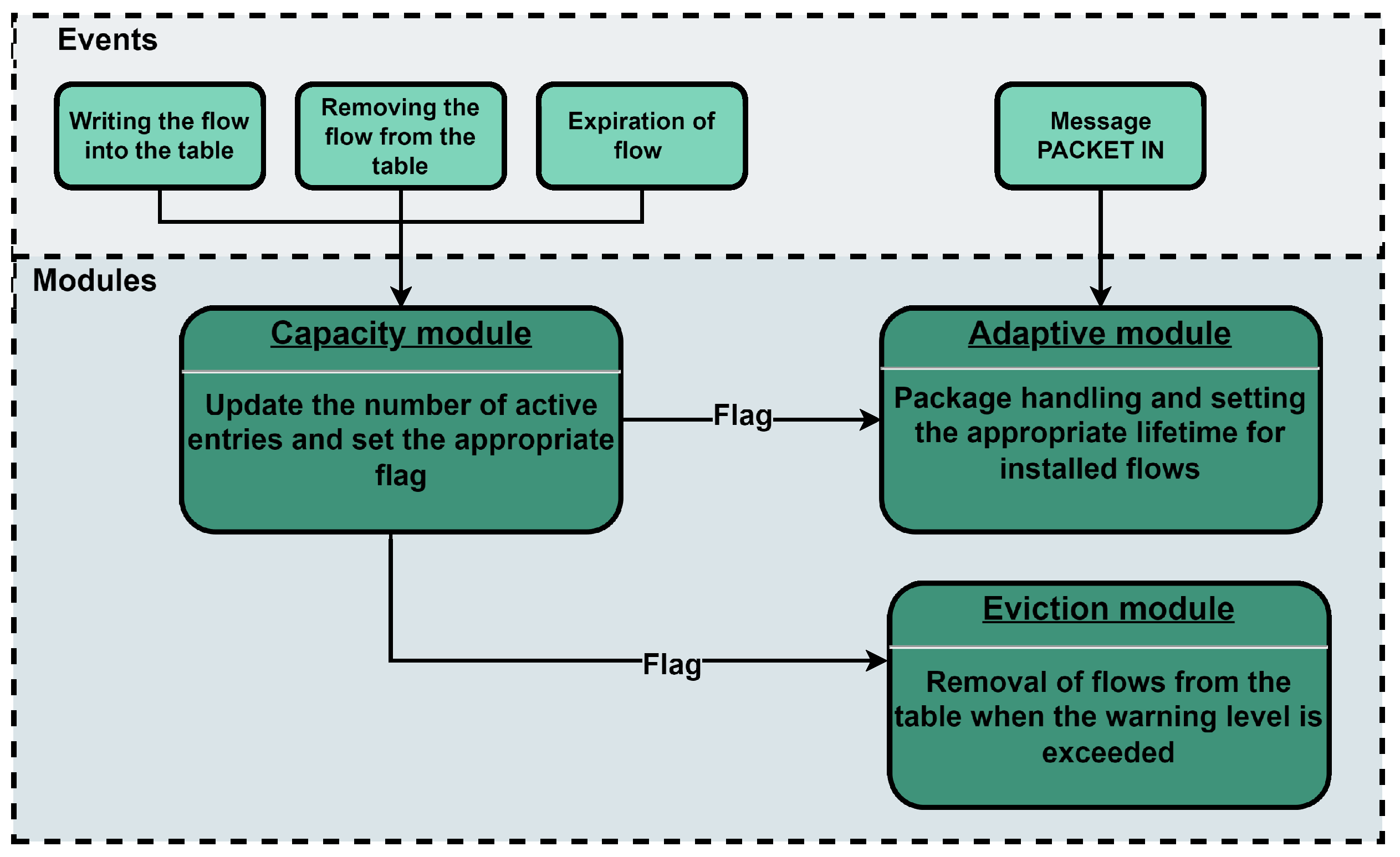
For the formulated problem, the solution is divided into three main aspects of the adaptive mechanism. The components of the solution are the adaptive module, the capacity module, and the eviction module. A diagram of the modules is presented in Figure 1. The respective modules are described below.

3.1. Capacity Module

This module is responsible for monitoring the filling of the flow entry table in the switch. It uses the controller’s auxiliary memory, in which it stores all the flows that are installed in the switch. The operation of the module is to build a replica of the flow table in the cache, based on which the controller calculates the TCAM usage level of the switch. It starts up every time an entry is sent to the flow table. The occupancy of the flow table is then checked, and then, depending on how full the flow table is, an appropriate flag is set. When the controller orders a flow to be installed in the switch’s memory, this is also recorded in its memory. Thus, the controller has information about the number of active entries in the memory of individual switches. The main task of this module is to set the flag on which the operation of other modules depends. The flag can be set at three levels, determined by the current filling of the switch’s memory: normal (0–50%), increased filling (51–97%), and warning (>97%).
Figure 1. Diagram of the modules of the adaptive mechanism.
Photonics 11 00595 g001

3.2. Adaptive Module

The adaptation module is a module that is responsible for setting the lifetimes of the flows that will be installed in the flow table in the switch. The developed mechanism will use both idle timeout and hard timeout. The calculated time between packet arrivals will be used to calculate the appropriate idle timeout. Both lifetime values will be allocated to flows adaptively, depending on the situation in which the switch’s TCAM is currently located. The operation of the module can be divided into three areas: initialization, setting idle timeout, and hard timeout. This module makes the proposed adaptive mechanism for managing flow lifetimes unique.
Initialization. When a packet arrives at the switch and does not find a match to the entry, a PACKET IN message is sent to the controller. Each packet is logged in the controller, so the controller knows whether it is the first occurrence of a message for a given flow or a subsequent one. If a packet with a given characteristic appears for the first time in a new flow, it is handled by the initialization module. This is the part that is responsible for assigning the idle timeout and hard timeout parameters to flows installed in the switch for the first time.
Most unpredictable flows and short flows will usually not occur again. They can therefore be handled only by the initialization part. This group includes short flows, i.e., short–large and short–small. When the packet does not find a match for any entry, the controller handles the packet. The controller instructs the switch to forward the packet. The rule is then installed in the switch table. After this, the controller will not need to support a similar package. For such flows, the value of lifetimes is set to the initialization value. Research shows that a significant number of network flows have packet-to-packet arrival times of less than 1 s. In addition, some flows are one-time. Referring to the tested flow characteristics, it was shown that 50% of the flows are below 1 s and that the 80th percentile of the times before the arrival of subsequent packets is also below 1 s [13]. For 75% of flows, lifetimes below 1 s are given in [25]. However, ref. [14], where an analysis of data from the university [30] was carried out, showed that in 76% of flows, the arrival time between subsequent packets is below 1 s. Therefore, when installing all new flows in the flow table, the controller will set their lifetime as equal to 1 s for both hard timeout and idle timeout.
Using the above solution allows you to avoid keeping entries with a small number of packets remaining in the flow table for a long time. Single packets and a large part of packets whose duration is less than 1 s are also handled in this way.
Idle timeout. Setting the flow lifetime with the idle timeout parameter is one of the main tasks of the adaptation module. It is performed for each re-request to handle a flow that has already occurred before and that the controller handled with the settings appropriate for the initialization part. The main calculation of the time-to-live value is performed in an adaptive manner using the arrival time between successive packets. Additionally, the value of the flag returned by the capacity module is taken into account, which determines how rigorously the lifetime will be calculated.
Collecting information about the time interval between subsequent flow packets is not easy and usually requires additional work on the controller’s part. This is due to the fact that, according to the idea of software-controlled networks, the control layer is separated from the forwarding layer, so the controller does not have information related to network traffic. In order for the controller to obtain such information, it is necessary to perform some additional actions. In the presented solution, the arrival time of subsequent packets, defined as r, is obtained by the controller using the cache memory. The controller stores the information in memory flows that have already appeared and were reported with a PACKET IN message, based on which the controller determines whether a given flow appeared for the first time or whether the message notification is a subsequent occurrence. If the flow occurs again, the controller records the timestamp of the packet’s arrival when the message arrives. Instead of immediately sending an entry to the flow table for this switch, it only sends a PACKET OUT message. The switch sends the packet to the appropriate location, but the rule for handling this packet is not installed on the switch. This results in the next packet arriving at the switch still not matching in the flow table, so the PACKET IN message is reported again to the controller. In the controller, in addition to the mechanism for distinguishing whether a packet comes from the first handling of this flow or whether it is the next appearance of a packet for the flow, there is a mechanism for the temporary handling of packets. This mechanism has a temporary structure in the cache, in which timestamps are written successively when a packet for a given flow arrives at the controller. The controller repeats the situation N times, and for each subsequent packet arrival, it calculates the average value of r, i.e., the interval between the arrivals of subsequent packets. When N packets arrive, the controller installs a packet rule for this flow in addition to ordering the packet to be sent to the appropriate location. The minimum value that N can take is two because at least two packets must arrive for the controller to be able to calculate the arrival time between these packets. If the value of N is set at more than two, then the current value of r is calculated as the average arrival time between successive packets.
Determining the idle timeout works in such a way that it also covers other possible situations occurring in the network traffic. The method used focuses on two flows from the long category (Figure 2), i.e., long–small and long–large. In order to set the appropriate flow lifetime for the idle timeout parameter, the presented line of reasoning was considered. The flow was set with a constant idle timeout, T1 = T2. In order to illustrate the difference, it was assumed that for the long–small flow, the interval between the arrivals of subsequent packets, r1, is very long, while for the long–large flow, the interval between the arrivals of subsequent packets, r2, is very small. The flows were named f1 for the long–small flow and f2 for the long–large flow, respectively. The time, T1, for a long–small flow is smaller than the interval between the arrivals of subsequent packets, r1. This means that for each subsequent packet that arrives at the switch, it will not find a match because the entry will be removed from the flow table. This will generate a PACKET IN message for each such packet, which in turn means that the controller will have to handle such a packet and reinstall the entry in the flow table. This situation will occur with each subsequent packet that arrives at the switch because the entry will be deleted again before the next packet arrives. Additionally, this will impose a load on the controller, which will have to handle a single packet of such a flow each time, so it will significantly increase the controller utilization load. In the second considered flow, the long–large flow, the value of the idle timeout parameter was set as time T2 equal to the value of T1. In this case, the time T2 is much longer than the time between the arrivals of successive packets, r2, for this flow; the time T2 is a multiple of the time r2. This means that if such a flow is entered into the flow table, each packet that arrives will be matched to this flow and will be handled in accordance with the rules written in the matched rule entry. Each packet match resets the idle timeout counter. The existence of this parameter will only start to make sense when the last packet of this flow arrives. This situation is much better than the previous one because the controller will not be forced to handle the flow with each new packet appearing in the switch. It just needs to be entered into the board when the first packet arrives. However, in this situation, the problem occurs after the last packet arrives because the T2 entry remains in the table even though it is inactive. In this situation, switch memory is used inefficiently because it takes up unnecessary space that could be used for new entries. Examples are shown in Figure 3 for the long–small flows, f1, and long–large flows, f2, respectively.
The above considerations show that setting a constant lifetime for flows in SDNs is ineffective. If the time is set too low, as is the case with the long–small flow, it causes over-communication with the controller and the flow, and instead of being handled by the switch, it actually starts being handled as much by the controller as by the switch. This leads to an inefficient use of controller resources. Too long a flow lifetime, as is the case with the long–large flow, causes the flow to dwell excessively in the switch’s memory even though it is no longer active and no packets are using the flow. This means that the TCAM is used inefficiently because such entries could be deleted earlier and free up space for new entries.
The setting of this parameter is performed for each resubmission of the flow service that occurred earlier. The main calculation of the idle timeout value uses the arrival time between successive packets. In addition, the value of the flag returned by the capacity module is considered, which determines how strictly the lifetime will be calculated. In order to effectively set the idle timeout parameter, the solution for the basic version uses the calculation of flow lifetimes according to Formula (1):
t i d l e = m a x ( [ r + T ] , t i d l e _ m i n )
where r is the arrival time between successive packets, T is a constant used to minimize the impact of the potential fluctuation of the packet interval (most often the value T = 1 ), and t i d l e _ m i n is the minimum value that the idle timeout parameter can take (most often t i d l e _ m i n = 1 ).
The calculation procedure used is the basic method for calculating the flow lifetime. The proposed mechanism uses three variants of this formula, which are used depending on the switch memory filling, i.e., on the flag set by the capacity module. More about the modifications of this formula is in the synthesis of the operation of the entire mechanism.
Hard timeout. Setting the flow lifetime using the hard timeout parameter is one of the next main tasks of the adaptation module. This parameter is calculated similarly to the idle timeout parameter. Setting this time for the flow is intended as a kind of security. This nature results from the property of setting the hard timeout time: after its expiry, the entry from the switch flow table is always deleted; therefore, setting this parameter means that, if it has not happened earlier due to setting the idle timeout counter or explicitly deleting the entry, then the flow will be removed from the flow table at this time. Therefore, this time is used as an upper security.
Setting this parameter performs security functions. Features of SDN-based data center traffic [17] have shown that the average transfer time of 80% of flows is less than eleven seconds. Also, as to the upper limit of the lifetime of flows, refer to [25], where it was found that nearly 90% of flows are below eleven seconds. A study conducted in [14] showed a similar relationship for 88% of flows. Similarly, this was investigated in [26], where it was reported that 90% of flows have a life of less than eleven seconds. Taking into account all the studies presented on duration, the hard timeout parameter was set to a value equal to t h a r d = 11 seconds for operation at the normal level of filling the flow array. For the intensified and warning levels, the values of the t h a r d parameter were 8 and 4 s, respectively.

3.3. Eviction Module

The tasks of this module include evicting packets when the switch memory is full or when the controller requests such an operation. This mechanism is very useful because it allows the controller to delete entries from the switch’s memory at any time. The lack of such a mechanism means that to remove entries from the flow table, it is necessary to wait until their lifetime expires.
In the proposed solution, the flow eviction mechanism is activated based on the flag value set by the capacity mechanism. Packet eviction is triggered when the flow table occupation is above 97%. This value was set below 100% because deleting entries when the flow table is full turned out to be inefficient. The adaptive mechanism tries to prepare in advance for the table to be full in order to be able to better handle subsequent packets that will require the controller to handle and enter the rule into the flow table. To deal with this effect, a buffer zone is introduced in the switch memory approach. Cache works well when you need to install many rules. This solution is based on the assumption that if the number of entries approaches a given warning level, it will most likely be required to handle flows that exceed the limit of the switch’s entry table capacity. Therefore, deletion operations are ordered in advance.
When removing packages, the controller works based on an algorithm that decides which package should be removed. The proposed mechanism enables cooperation with various types of algorithms responsible for selecting the flow to be removed. In accordance with previous research that showed the implementation weakness of the LRU algorithm [31], the Random flow removal algorithm was chosen as the main algorithm in the proposed solution. As shown in research by IBM researchers, the random flow removal algorithm performs significantly better than the FIFO algorithm [13]. However, some simulations tested a solution using the FIFO algorithm.
In the next section, we show carefully selected simulation results that demonstrate the efficiency of our proposal.

4. Simulations

The solution was implemented using the RYU controller. It is a controller developed for software-controlled networks written in Python. Simulations were performed in the Mininet environment, which provides simulations of network infrastructure, where Open vSwitch was used as a switch. The solution was implemented, and simulations were performed with the OpenFlow protocol version 1.3.1, due to the use of this protocol by many hardware devices. The whole simulation was simulated using the Virtual Box virtual machine, on which the Ubuntu 20.04 operating system was installed. TCP Replay was used as the traffic simulation tool.
For model training and evaluation, we used a dataset from the Measurement and Analysis on the WIDE Internet (WIDE MAWI) Working Group collection [32]. WIDE MAWI collects network traffic measurements, and provides analysis, evaluation, and verification. The mechanism for the adaptive management of flow lifetimes was compared with static settings of idle timeout and hard timeout parameters. For the adaptive mechanism, simulations were performed with a value of N = 3 , giving details on for how many packets the average value of time between packet arrivals should be counted. Measurements were made for 1000 and 3000 TCAM capacity entries. The graphs indicate the 95% confidence intervals determined by the bootstrap method.
A wide variety of measurements were made in the simulations. The mechanism for the adaptive management of flow lifetimes was compared with tangential settings of idle timeout and hard timeout parameters, considering a combination of Random and FIFO eviction policies. The numbers in the names of the simulations indicate for what time the corresponding parameter was set.

4.1. Packet Handling Ratio

To compare the solution, the packet handling ratio was used. It tells what number of packets were matched in the flow table of the switch to the number of packets handled by the switch and those that the controller had to handle when installing a new flow. It is defined as follows: The number of packets that pass through the switch using the rules stored in the flow table is c. The number of entries sent by the controller to the switch, modifying the flow table so that packets can be handled by the switch, is s c . The service ratio is described by Equation (2).
h a n d l i n g r a t i o = c / ( c + s c )
In order to compare the solution, the packet handling ratio was used, which is a coefficient indicating the number of packets that were matched in the switch flow table to the number of packets handled by the switch and those that the controller had to handle when installing a new flow in the switch table.
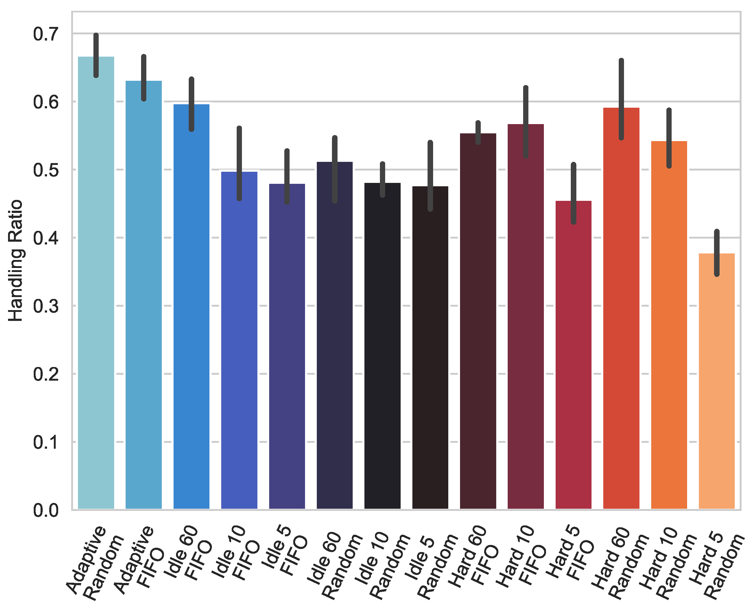
Figure 4 and Figure 5 show the results for simulations with the adopted TCAM and 1000 and 3000 entries, respectively. The proposed adaptive method was compared with static idle timeout and hard timeout settings. For the adaptive mechanism, FIFO and Random flow eviction were used. Similarly, for static settings, the combination of the eviction of Random and FIFO flows was also tested. The proposed solution of the adaptive mechanism in the figures is named Adaptive Random and Adaptive FIFO, respectively, for the adaptive mechanism with the Random and FIFO flow eviction policies used. The simulations were performed several times, and then the average value was calculated, including the 95% confidence interval, which was calculated based on the bootstrap method.
Figure 4 and Figure 5 show that the proposed algorithm has a higher service factor for a larger array size. A similar relationship occurs for the static setting of the idle timeout and hard timeout parameters. This is because a larger memory size allows more entries to be stored in it, which results in a higher rate of packet handling by the switch. Figure 4 and Figure 5 also show that the proposed algorithm has a higher service rate compared to methods with set static values of the flow lifetime. The results also indicate that algorithms with greater timeout values, i.e., 60 s, tend to provide greater ratios, although the difference is not very significant.
This implies that the proposed algorithm manages the same traffic with fewer requests to write flow rules to the switch memory. Based on the results presented in Figure 5, it can be observed that the proposed algorithm is highly effective at maintaining flows in the table for an extended period, during which new packets continuously appear and there is no need for the controller to re-handle them. This is particularly evident when compared to setting the static flow lifetime for the hard timeout parameter to 5 s. For these methods, the switch service factor is considerably lower than it is for the proposed method. This is due to the fact that the hard timeout parameter is responsible for deleting entries regardless of whether there are new packages that have been matched to it. Consequently, after 5 s, the flow is deleted and must be re-handled by the controller and re-installed in the switch’s memory. Consequently, the presented mechanism for adaptive management of flow lifetimes is demonstrated to utilize more efficiently the available space in the switch memory. Our mechanism performs better for any simple queue with timeout values of even 60 s. Therefore, we were able to achieve a better handling ratio with a much smaller required table capacity, as will be shown in subsequent figures. The results also indicate that algorithms with greater timeout values, i.e., 60 s, tend to provide a greater ratio, although the difference is not very significant.

4.2. Capacity Lack of Storage Indicator

The capacity lack of storage indicator (3) indicates how many packets were mismatched due to a lack of space in the switch’s flow table.
c a p a c i t y l a c k o f s t o r a g e i n d i c a t o r = ( f m / t m ) 100
where f m packets are not supported due to a lack of space for new entries in the switch, and t m are all packets that appear in the switch and do not find a match.
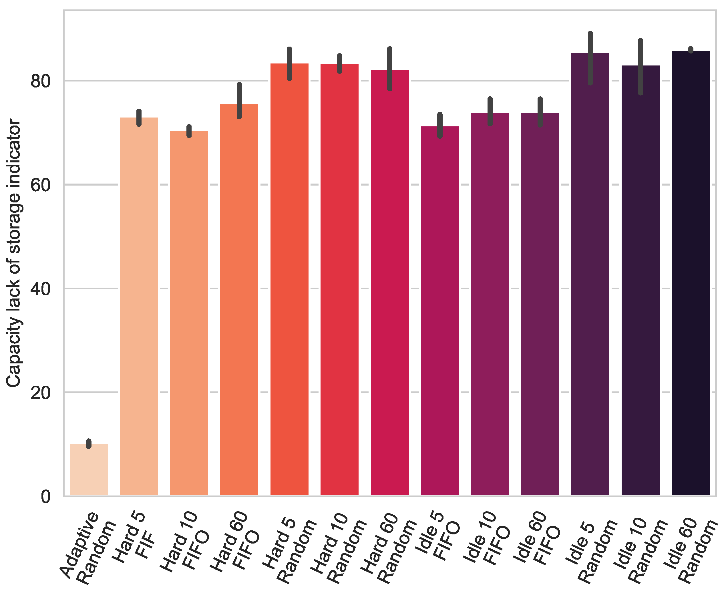
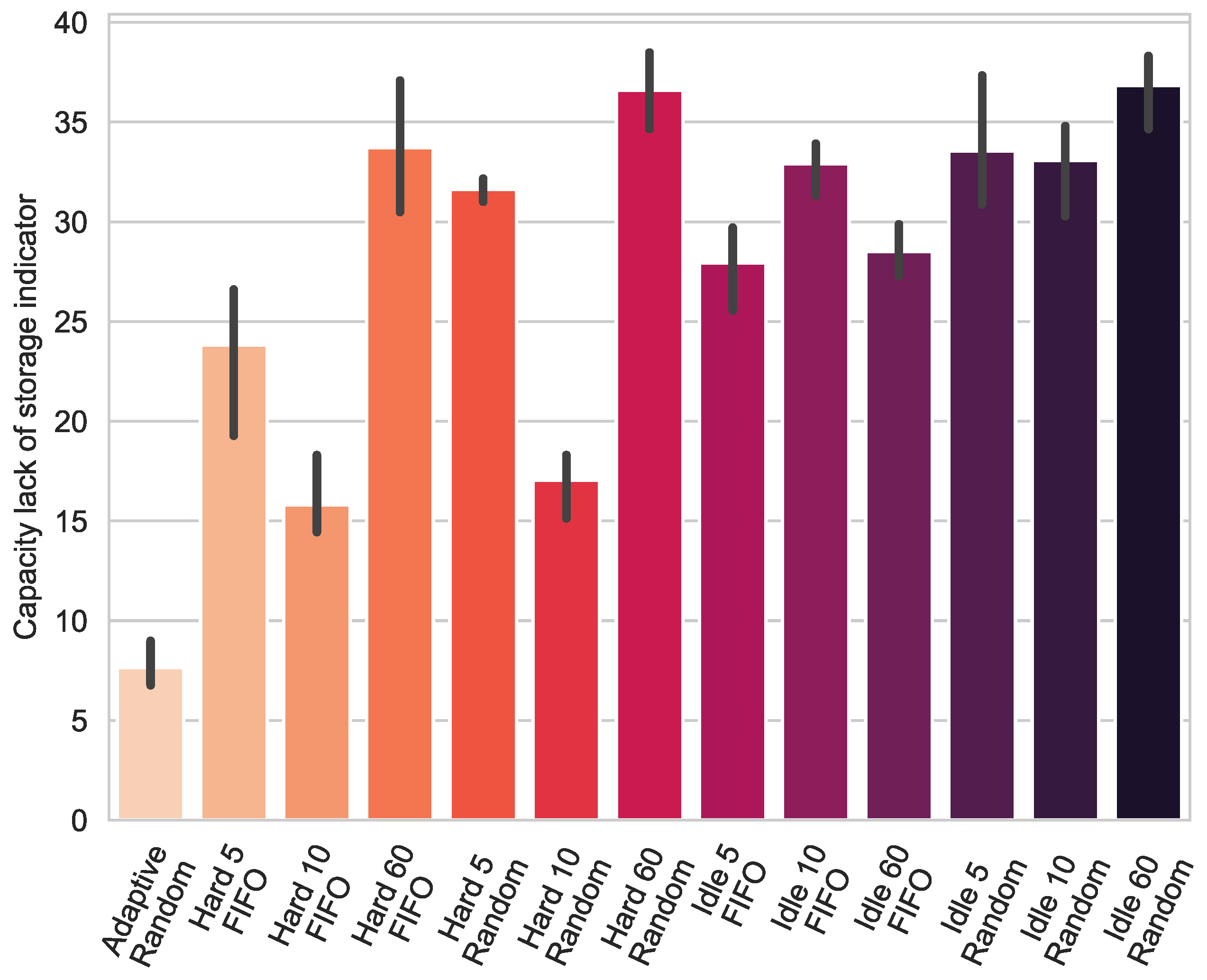
Figure 6 and Figure 7 show a capacity lacking a storage indicator for a memory size of 1000 and 3000 thousand entries. This means that the algorithm is much less likely to completely load the switch’s memory; thus, fewer rules are rejected.
The out-of-capacity indicator indicates how many packets were mismatched due to a lack of space in the switch’s flow table. When a packet arrives at the switch that does not match one in the table, it is handled by the controller. The controller instructs the flow to be installed this way, serving the package and any subsequent similar packages that match the saved flow. However, it may happen that the entry was not added to the flow table because there was no space. In this case, the next packet that arrives at the switch again does not find a match in the flow table, requiring it to be handled by the controller. The lack of a capacity indicator means that the controller must handle those packets marked as fm. These are packages that are not supported due to a lack of space for new entries in the switch. The number of all packets that arrive at the switch and do not find a match is tm. This indicator is expressed by Formula (3).
In the presented simulations, the proposed method with the Random packet eviction algorithm was used because simulations conducted for the FIFO algorithm give very similar results. The mechanism for the adaptive management of flow lifetimes is marked as Adaptive Random. Simulations were performed several times, and then, similarly to the service factor, the average value was calculated, including the 95% confidence interval calculated based on the bootstrap method.
Figure 6 and Figure 7 show the out-of-capacity rate for memory sizes of 1000 and 3000 thousand entries, respectively. The presented simulations show that, for a smaller memory size, there are more unhandled packets due to a lack of space in the flow table. In this situation, a more common phenomenon occurs that forces the controller to handle the packet, resulting in the controller sending a message adding an entry to the switch’s memory, but due to a lack of space, the rule is rejected. This means that the next packet that could be handled in accordance with the rejected rule is, due to its lack of space, sent again to the controller, which once more orders an entry to be added to the flow table. This situation will continue until the controller explicitly requests the entry be deleted or the entry is deleted due to the expiration of its time-to-live. Both Figure 6 and Figure 7 show a significant difference between the proposed adaptive mechanism and methods with set static flow lifetimes. This means that the number of packets that do not find a suitable match in the entry table due to switch memory overflow is much smaller in the adaptation mechanism. This is mainly due to the fact that the mechanism operates on three levels: normal, where entries are stored in the table as long as possible; increased overflow, where more restrictive rules are applied regarding the setting of flow lifetimes; and warning, where when a certain value is exceeded, the packet eviction algorithm is activated. In the proposed solution, the warning level is set to 97% of the maximum TCAM size; this value was selected experimentally. Other mechanisms operate at the level of 70–80 percent of the table capacity, regardless of the used flow timeout and type of queue. There are a few differences that are insignificant in relation to the outcome of our algorithm.
As the results show, setting a threshold that triggers the early eviction of packets allows you to prepare for handling subsequent packets when the switch memory is approaching full.
As shown, the adaptive flow timing mechanism can remove an entry early to sufficiently minimize the probability of running out of space for the entry due to its memory being full. It can be argued that deleting entries before the table is full is a suboptimal use of available space. However, combining the results presented in Figure 6 and Figure 7 with the results presented in Figure 4 and Figure 5, it can be concluded that when it is possible to store entries in the table, the adaptive mechanism does so for as long as possible, and when the switch memory is close to overflowing, the adaptive mechanism allows you to prepare for such an eventuality. The presented properties show that the mechanism of adaptive management of flow lifetimes can adapt to various circumstances and conditions that may occur in the network, which makes the proposed mechanism a very flexible tool.

4.3. The Dependence of the Parameter N

The proposed mechanism to calculate the average arrival time between consecutive packets r uses N packet arrivals to the controller. Only after N packets have arrived, flows with calculated lifetime values are installed in the controller.
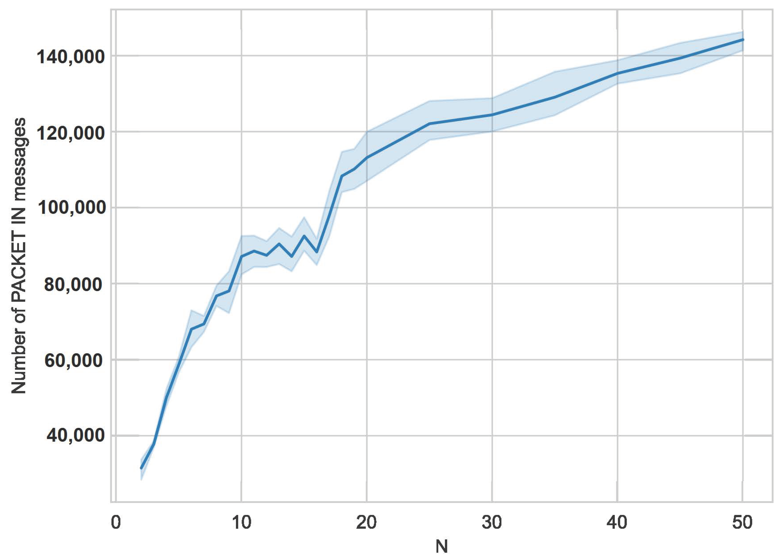
Figure 9 shows an almost linear increase in the number of PACKET IN messages for N from 2 to 10. For larger values of the number N, the number of PACKET IN messages coming to the controller grows more slowly.
Obtaining the value of r by the controller in the presented mechanism is costly because, to handle one flow, the switch needs to generate a larger number of PACKET IN messages than would be the case if a given flow were handled immediately. Simulations were performed for a size of 1000 switch memory entries.
Figure 8 presents the average values calculated for the PACKET IN message, considering the 95% confidence interval calculated on the basis of the bootstrap method. As the number of N increases, the number of PACKET IN messages sent to the controller increases. This is the cost of the presented mechanism because, in order to obtain a more accurate value of the average time between the arrivals of subsequent packets r, the number N must be increased, indicating for how many packets the average value is to be calculated. For small values presented in Figure 9, where N is in the range from two to ten, a linear increase in PACKET IN messages can be observed as the number of N increases. This is due to the fact that the flows for which the mechanism calculates the time between subsequent packet arrivals usually have more than the currently set N packets. In practice, this means that failure to install a rule for a flow results in subsequent appearances of the PACKET IN message for the same flows, which is a desired effect, but at the same time, a cost is incurred by the controller resulting from the handling of these packets. Note, however, that the increase is relative to the smallest possible value of N of two, where the number of PACKET IN messages is about thirty-five thousand, it is not directly proportional to the next value of N. This is caused by the effect of the correct operation of the initialization module, which handles about 70% of the flows in the first PACKET IN message in the controller. The remaining 30% is the part of the flow that is handled by setting the flow lifetimes using information about the time intervals between subsequent packets. The simulations carried out confirm the validity of the assumptions made for the module and the research on which the principle of operation of this module was based.
Figure 9 also takes into account the 95% confidence interval for the average number of PACKET IN messages and the calculated average value depending on the number N. Figure 9 shows the dependence of the PACKET IN messages on the set number N in a broader perspective compared to Figure 8 because the number N varies from two to fifty. This is better illustrated by another property for the settings of the number N, which shows that for increasingly larger values, the number of PACKET IN messages to the controller grows increasingly slowly. This is because, for example, when N is set to thirty, when reporting subsequent PACKET IN messages in order to calculate the average value of time between subsequent packets, a large part of the packets will be handled, and the installation of this flow in the table will not take place because it will no longer be active.

4.4. Impact of Mechanism on Network Traffic

In order to check the impact of the adaptive flow time management mechanism on network traffic, service time was measured for the bigFlows dataset, which was simulated using the TCP replay tool. The TCP replay functionality was used, which allows the captured traffic to be installed on the network at any speed. This means that the traffic reproduced during the simulation used the maximum resources of the switch and controller in such a way that traffic coming to the switch from other hosts could only be handled after the traffic coming from the dataset had been serviced. The time comparison was made for a TCAM with a capacity of 1000 entries. The adaptive flow timing mechanism was tested with the default Random packet eviction setting, marked as Adaptive Random in Figure 10. It was compared with setting static lifetimes for the version using the Random eviction algorithm. The set values of flow lifetimes were 5, 10, and 60 for the hard timeout and idle timeout parameters, respectively. Additionally, in order to compare the methods with the lifetime setting, the same dataset was used and tested with the default version of the simple_switch_13 controller, which is provided with the basic version of the Ryu software. This controller is a very simple version because only the input port, destination address, and source address are taken into account when analyzing packets. The service time calculated in the measurements is the time the switch needs to service the dataset reproduced by the TCP replay simulator. When the reproduced traffic is simulated at maximum speed, it blocks the switch’s resources for a period of time, and it is unable to handle any other incoming traffic, for example, from another host. This time also takes into account communication with the controller during this process.
The times presented in Figure 10 were calculated as the average of several simulations, and the 95% confidence interval calculated based on the bootstrap method was also considered. As Figure 10 shows, the fastest traffic was handled using a simple version of the controller, but it should be noted that this controller does not support protocols such as UDP or TCP, and practically all traffic was handled by the switch. Because traffic was only distinguished by its source and destination addresses, it only needed to install two flows in the switch table to handle this traffic. Compared to the basic version of the controller, the adaptive flow time management mechanism handled the sample dataset a little longer, but it should be kept in mind that it supports both TCP and UDP protocols. The figure indicates that our mechanism handles large flows only slightly worse than the simplest possible flow-handling procedure, which is a great outcome. On the other hand, the efficiency is much better than in the case where other mechanisms are implemented.
Such action involves a better matching of the traffic occurring in the network but also requires the installation of a larger number of flows, which involves a larger number of messages sent to the controller. Ultimately, this translates into longer service times compared to a simpler controller. However, when comparing the adaptive mechanism for managing flow lifetimes to the static method of setting flow lifetimes, the proposed adaptive mechanism handles traffic faster, mainly due to its appropriate preparation for the situation of flow table overflow, which reduces excessive communication of the switch with the controller. It should also be noted that the proposed adaptive method is able to handle traffic faster, despite the occurrence of additional communication with the controller, in order to calculate the average value between the arrivals of subsequent packets.

5. Conclusions

The mechanism presented in the paper combines several concepts and creates a complete solution. It uses the setting of lifetimes with both the idle timeout and hard timeout parameters. To calculate the idle timeout value, calculations have been proposed that use the arrival time between successive flow packets. A method has been developed that allows the controller to obtain the average value of time between successive flow packets for the first N flow packets. Lifetime values are set depending on the current filling level of the switch flow table. Initialization lifetimes of the flow were used, which are installed for the first time the flow is served. In the mechanism, the table filling level has been divided into three zones, which determine the approach used to assign appropriate lifetime values for the installed flows. For the first level, the policy used is to store entries in the flow table for as long as possible; this applies in situations of low network load. When setting the flow lifetimes, the next level considers the packet frequency of a given flow so that the traffic is handled by this flow, but at the same time, so that the flow does not take up too much space in the table if it is no longer active. The last level of array filling is the level where the array begins to fill with entries, and the set lifetimes for flows are treated rigorously. Additionally, after exceeding the appropriate table occupancy threshold, the mechanism starts evicting packets based on the Random algorithm to prepare space for subsequent entries that require servicing. The results indicate that the presented mechanism can handle the same amount of traffic by performing fewer requests to write rules to the switch memory compared to the static time-to-live setting. Additionally, for the presented mechanism, a smaller number of packets are mismatched due to a lack of space in the switch memory, which is a huge advantage of the proposed solution.
The proposed mechanism works well as is. However, we plan to extend its functionalities in the future. The algorithm can be extended towards additional classifications of flows based on a higher number of characteristics of the generated traffic. There are a plethora of possibilities regarding the flow classification process. For example, current studies focus on classifying flows based on only the first packet of the flow and achieve adequate accuracy. In our mechanism, it is also possible to add another packet eviction mechanism that will achieve even greater efficiency than the one presented.

Author Contributions

Conceptualization, K.R. and R.W.; methodology, K.R. and R.W.; validation, W.Z., J.D. and R.W.; formal analysis, K.R.; investigation, K.R., W.Z., J.D. and R.W.; resources, K.R. and R.W.; writing—original draft preparation, K.R. and W.Z.; writing—review and editing, J.D. and R.W.; visualization, K.R.; supervision, J.D. and R.W.; project administration, R.W. All authors have read and agreed to the published version of the manuscript.

Funding

This work was supported by the Polish Ministry of Science and Higher Education with the subvention funds of the Faculty of Computer Science, Electronics and Telecommunications of AGH University.

Data Availability Statement

Data are contained within the article.

Conflicts of Interest

The authors declare no conflicts of interest.

References

  1. Jha, R.K.; Llah, B.N.M. Software Defined Optical Networks (SDON): Proposed architecture and comparative analysis. J. Eur. Opt.-Soc.-Rapid Publ. 2019, 15, 16. [Google Scholar] [CrossRef]
  2. Díaz-Montiel, A.A.; Lantz, B.; Yu, J.; Kilper, D.; Ruffini, M. Real-Time QoT Estimation through SDN Control Plane Monitoring Evaluated in Mininet-Optical. IEEE Photonics Technol. Lett. 2021, 33, 1050–1053. [Google Scholar] [CrossRef]
  3. Tao, Y.; Ranaweera, C.; Edirisinghe, S.; Lim, C.; Nirmalathas, A.; Wosinska, L.; Song, T. Automated Control Plane for Reconfigurable Optical Crosshaul in Next Generation RAN. In Proceedings of the 2024 Optical Fiber Communications Conference and Exhibition (OFC), San Diego, CA, USA, 5–9 March 2024; pp. 1–3. [Google Scholar]
  4. Muñoz, R.; Lohani, V.; Casellas, R.; Martínez, R.; Vilalta, R. Control of Packet over Multi-Granular Optical Networks combining Wavelength, Waveband and Spatial Switching For 6G transport. In Proceedings of the 2024 Optical Fiber Communications Conference and Exhibition (OFC), San Diego, CA, USA, 5–9 March 2024; pp. 1–3. [Google Scholar]
  5. Bakopoulos, P.; Patronas, G.; Terzenidis, N.; Wertheimer, Z.A.; Kashinkunti, P.; Syrivelis, D.; Zahavi, E.; Capps, L.; Argyris, N.; Yeager, L.; et al. Photonic switched networking for data centers and advanced computing systems. In Proceedings of the 2024 Optical Fiber Communications Conference and Exhibition (OFC), San Diego, CA, USA, 5–9 March 2024; pp. 1–3. [Google Scholar]
  6. Azodolmolky, S.; Nejabati, R.; Escalona, E.; Jayakumar, R.; Efstathiou, N.; Simeonidou, D. Integrated OpenFlow–GMPLS control plane: An overlay model for software defined packet over optical networks. Opt. Express 2011, 19, B421. [Google Scholar] [CrossRef]
  7. Ghiasian, A. Impact of TCAM size on power efficiency in a network of OpenFlow switches. IET Netw. 2020, 9, 367–371. [Google Scholar] [CrossRef]
  8. Nguyen, X.N.; Saucez, D.; Barakat, C.; Turletti, T. Rules Placement Problem in OpenFlow Networks: A Survey. IEEE Commun. Surv. Tutor. 2016, 18, 1273–1286. [Google Scholar] [CrossRef]
  9. Zarek, A. OpenFlow Timeouts Demystified; University of Toronto: Toronto, ON, Canada, 2012. [Google Scholar]
  10. Lee, B.S.; Kanagavelu, R.; Aung, K.M.M. An efficient flow cache algorithm with improved fairness in Software-Defined Data Center Networks. In Proceedings of the 2013 IEEE 2nd International Conference on Cloud Networking (CloudNet), San Francisco, CA, USA, 11–13 November 2013; pp. 18–24. [Google Scholar] [CrossRef]
  11. Kim, E.D.; Choi, Y.; Lee, S.I.; Shin, M.K.; Kim, H.J. Flow table management scheme applying an LRU caching algorithm. In Proceedings of the 2014 International Conference on Information and Communication Technology Convergence (ICTC), Busan, Republic of Korea, 22–24 October 2014; pp. 335–340. [Google Scholar] [CrossRef]
  12. Kim, E.D.; Lee, S.I.; Choi, Y.; Shin, M.K.; Kim, H.J. A flow entry management scheme for reducing controller overhead. In Proceedings of the 16th International Conference on Advanced Communication Technology, Pyeong Chang, Republic of Korea, 16–19 February 2014; pp. 754–757. [Google Scholar] [CrossRef]
  13. Vishnoi, A.; Poddar, R.; Mann, V.; Bhattacharya, S. Effective switch memory management in OpenFlow networks. In Proceedings of the 8th ACM International Conference on Distributed Event-Based Systems, Mumbai, India, 26 May 2014. [Google Scholar] [CrossRef]
  14. Zhu, H.; Fan, H.; Luo, X.; Jin, Y. Intelligent timeout master: Dynamic timeout for SDN-based data centers. In Proceedings of the 2015 IFIP/IEEE International Symposium on Integrated Network Management (IM), Ottawa, ON, Canada, 11–15 May 2015; pp. 734–737. [Google Scholar] [CrossRef]
  15. Li, H.; Guo, S.; Wu, C.; Li, J. FDRC: Flow-driven rule caching optimization in software defined networking. In Proceedings of the 2015 IEEE International Conference on Communications (ICC), London, UK, 8–12 June 2015; pp. 5777–5782. [Google Scholar] [CrossRef]
  16. Liu, Y.; Tang, B.; Yuan, D.; Ran, J.; Hu, H. A dynamic adaptive timeout approach for SDN switch. In Proceedings of the 2016 2nd IEEE International Conference on Computer and Communications (ICCC), Chengdu, China, 14–17 October 2016; pp. 2577–2582. [Google Scholar] [CrossRef]
  17. Lu, M.; Deng, W.; Shi, Y. TF-IdleTimeout: Improving efficiency of TCAM in SDN by dynamically adjusting flow entry lifecycle. In Proceedings of the 2016 IEEE International Conference on Systems, Man, and Cybernetics (SMC), Budapest, Hungary, 9–12 October 2016; pp. 002681–002686. [Google Scholar] [CrossRef]
  18. Challa, R.; Lee, Y.; Choo, H. Intelligent eviction strategy for efficient flow table management in OpenFlow Switches. In Proceedings of the 2016 IEEE NetSoft Conference and Workshops (NetSoft), Seoul, Republic of Korea, 6 June 2016; pp. 312–318. [Google Scholar] [CrossRef]
  19. Li, Z.; Hu, Y.; Zhang, X. SDN Flow Entry Adaptive Timeout Mechanism based on Resource Preference. Iop Conf. Ser. Mater. Sci. Eng. 2019, 569, 042018. [Google Scholar] [CrossRef]
  20. Guo, Z.; Liu, R.; Xu, Y.; Gushchin, A.; Walid, A.; Chao, H. STAR: Preventing Flow-table Overflow in Software-Defined Networks. Comput. Netw. 2017, 125, 15–25. [Google Scholar] [CrossRef]
  21. Zhang, L.; Wang, S.; Xu, S.; Lin, R.; Yu, H. TimeoutX: An Adaptive Flow Table Management Method in Software Defined Networks. In Proceedings of the 2015 IEEE Global Communications Conference (GLOBECOM), San Diego, CA, USA, 6–10 December 2015; pp. 1–6. [Google Scholar] [CrossRef]
  22. Li, X.; Huang, Y. A Flow Table with Two-Stage Timeout Mechanism for SDN Switches. In Proceedings of the 2019 IEEE 21st International Conference on High Performance Computing and Communications; IEEE 17th International Conference on Smart City; IEEE 5th International Conference on Data Science and Systems (HPCC/SmartCity/DSS), Zhangjiajie, China, 10–12 August 2019; pp. 1804–1809. [Google Scholar] [CrossRef]
  23. Xu, X.; Hu, L.; Lin, H.; Fan, Z. An Adaptive Flow Table Adjustment Algorithm for SDN. In Proceedings of the 2019 IEEE 21st International Conference on High Performance Computing and Communications; IEEE 17th International Conference on Smart City; IEEE 5th International Conference on Data Science and Systems (HPCC/SmartCity/DSS), Zhangjiajie, China, 10–12 August 2019; pp. 1779–1784. [Google Scholar] [CrossRef]
  24. Li, Q.; Huang, N.; Wang, D.; Li, X.; Jiang, Y.; Song, Z. HQTimer: A Hybrid Q-Learning-Based Timeout Mechanism in Software-Defined Networks. IEEE Trans. Netw. Serv. Manag. 2019, 16, 153–166. [Google Scholar] [CrossRef]
  25. Panda, A.; Samal, S.S.; Turuk, A.K.; Panda, A.; Venkatesh, V.C. Dynamic Hard Timeout based Flow Table Management in Openflow enabled SDN. In Proceedings of the 2019 International Conference on Vision Towards Emerging Trends in Communication and Networking (ViTECoN), Vellore, India, 30–31 March 2019; pp. 1–6. [Google Scholar] [CrossRef]
  26. Isyaku, B.; Kamat, M.B.; Abu Bakar, K.b.; Mohd Zahid, M.S.; Ghaleb, F.A. IHTA: Dynamic Idle-Hard Timeout Allocation Algorithm based OpenFlow Switch. In Proceedings of the 2020 IEEE 10th Symposium on Computer Applications & Industrial Electronics (ISCAIE), Malaysia, 18–19 April 2020; pp. 170–175. [Google Scholar] [CrossRef]
  27. Yang, H.; Riley, G.F.; Blough, D.M. STEREOS: Smart Table EntRy Eviction for OpenFlow Switches. IEEE J. Sel. Areas Commun. 2020, 38, 377–388. [Google Scholar] [CrossRef]
  28. Abbasi, M.; Maleki, S.; Jeon, G.; Khosravi, M.R.; Abdoli, H. An intelligent method for reducing the overhead of analysing big data flows in Openflow switch. IET Commun. 2022, 16, 548–559. [Google Scholar] [CrossRef]
  29. Mendiboure, L.; Chalouf, M.A.; Krief, F. Load-Aware and Mobility-Aware Flow Rules Management in Software Defined Vehicular Access Networks. IEEE Access 2020, 8, 167411–167424. [Google Scholar] [CrossRef]
  30. Benson, T.; Akella, A.; Maltz, D. Network Traffic Characteristics of Data Centers in the Wild. In Proceedings of the 10th ACM SIGCOMM Conference on Internet Measurement, Melbourne, Australia, 1–3 November 2010; pp. 267–280. [Google Scholar] [CrossRef]
  31. Isyaku, B.; Mohd Zahid, M.S.; Bte Kamat, M.; Abu Bakar, K.; Ghaleb, F.A. Software Defined Networking Flow Table Management of OpenFlow Switches Performance and Security Challenges: A Survey. Future Internet 2020, 12, 147. [Google Scholar] [CrossRef]
  32. Traffic Trace Info. Available online: http://mawi.wide.ad.jp/mawi/samplepoint-F/2022/202209091400.html (accessed on 24 May 2024).
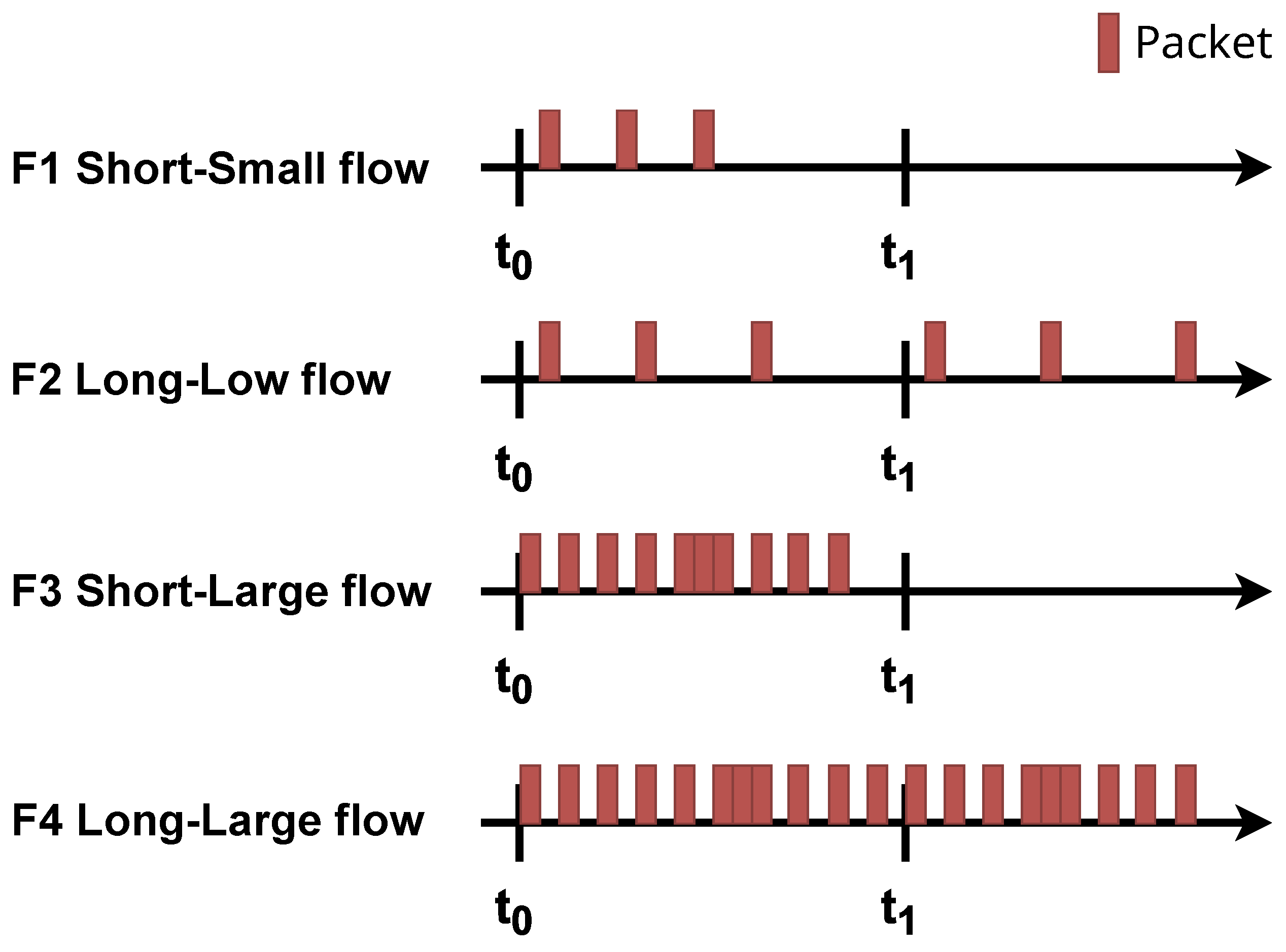
Figure 2. Types of flows depending on the number and arrival times of packets (own study based on [31]).
Photonics 11 00595 g002
Figure 3. Too small and too large flow lifetimes (based on [14]).
Photonics 11 00595 g003
Figure 4. Handling ratio for memory with 1000 entries.
Photonics 11 00595 g004
Figure 5. Handling ratio for memory with 3000 entries.
Photonics 11 00595 g005
Figure 6. Capacity lack of storage indicator for memory size of 1000 entries.
Photonics 11 00595 g006
Figure 7. Capacity lack of storage indicator for memory size of 3000 entries.
Photonics 11 00595 g007
Figure 8. The number of PACKET IN messages relative to the number N for N from 2 to 50 (N: the number of packets for which the average arrival time between successive packets is calculated).
Photonics 11 00595 g008
Figure 9. Number of PACKET IN messages in relation to the number N for N from 2 to 10 (N: number of packets for which the average arrival time between consecutive packets is calculated).
Photonics 11 00595 g009
Figure 10. Service time of all packages for bigFlows data at maximum simulation speed.
Photonics 11 00595 g010
Disclaimer/Publisher’s Note: The statements, opinions and data contained in all publications are solely those of the individual author(s) and contributor(s) and not of MDPI and/or the editor(s). MDPI and/or the editor(s) disclaim responsibility for any injury to people or property resulting from any ideas, methods, instructions or products referred to in the content.