Abstract
As a space camera works in orbit, the stress rebound caused by gravity inevitably results in the deformation of its optomechanical structure, and the relative position change between different optical components will affect the Line-Of-Sight pointing of the camera. In this paper, the optical sensitivity calculation of a space camera’s Line-Of-Sight pointing is realized based on the optomechanical constraint equations, and the Line-Of-Sight equations are constructed using the second type of response (DRESP2) method to realize an optomechanical integrated analysis of the camera’s Line-Of-Sight stability at the structural finite element solver level. The verification results show that the Line-Of-Sight stability error is 6.38%, meaning that this method can identify the sensitive optical elements of the optical system efficiently and quickly. Thus, the method in this paper has important significance as a reference for the analysis of the Line-Of-Sight stability of complex optical systems.
1. Introduction
From development to on-orbit operation, space cameras need to go through various environments, such as the laboratory, transportation, launch, and orbit. The pointing accuracy of the Line-Of-Sight of a space camera system will be affected by many complex environmental factors [1]. High-precision analysis and the design of Line-Of-Sight pointing are key technologies that need our full attention and in-depth research.
The traditional optomechanical system usually adopts the iterative design method of Line-Of-Sight pointing recalculation after the completion of component design [2], which cannot create a balanced impact assessment of optical, mechanical, thermal, and other factors [3]. At present, the mainstream method to ensure the Line-Of-Sight pointing of a space camera domestically and abroad is to use the integrated comprehensive design of a star sensor and camera [4,5], integrated optomechanical analysis technology that can also be used for simulation research. In addition, the integrated optomechanical analysis of Line-Of-Sight stability is mostly based on the optical sensitivity coefficient matrix generated by optical design software and the rigid body motions calculated by finite element calculation [6,7]. There are few studies on the theoretical calculation method of optical sensitivity coefficients. Therefore, an optical sensitivity coefficient calculation method based on the optomechanical constraint equations is proposed to analyze the stability of the visual axis, which has an important role in helping mechanical engineers understand the optical properties of the designed products and how to improve them.
This paper takes the off-axis three-mirror optical system of a space camera as an example. A structural finite element solver-level integrated optomechanical analysis method based on the theory of the optomechanical constraint equations is proposed to study the influence of mechanical loading on the Line-Of-Sight stability of the space camera, which can be used to understand the complex environment surrounding the camera and locate the sensitive optical elements that can be used to improve the design of its optomechanical system.
2. The Optomechanical Constraint Equations
Through the joint derivation of first-order optical theories such as the Gaussian imaging formula, paraxial imaging principle, magnification ratio formula, and geometric relations, the functional relationship between the change in the image’s position and size and the change caused by the movement of optical elements is established, which is the optomechanical influence function [8,9]. According to the linear part of the optomechanical influence function, the coefficient matrix of the influence functions about each optical element can be obtained.
The matrix of the optomechanical influence coefficients for the curved mirror under study is shown in Table 1 [10]. For example, the X-direction motion of the image is a function of the X-direction motion of the object (Txo), the Y-direction motion of the object (Tyo), the relative angle θ, and the magnification M, which can be expressed as

Table 1.
The matrix of optomechanical influence coefficients for the curved mirror.
The same equation will apply to the rotation of an optical element about an axis. the rotation of an optical element about the X-axis is Rxo.
Where M is the magnification at which the curved mirror works. The relative angle θ is a rotation angle, which can make the optical axis turn out of its plane, which is where the object is rotated about its own Z-axis, thus turning the object’s X-axis into its Y-axis. The image distance s′ is the distance from the imaging point to the vertex of the mirror. The focal length f is the distance from the vertex of the mirror to the focal point.
The optomechanical constraint equations are used to study the change in image position and size caused by the subtle motion of optical elements in the system-level state. Changes in the position and focal length of each optical element (Txo, Tyo, Tzo, Rxo, Ryo, Rzo, Δf) will cause changes in the position and the size of the image point about the optical system (Txi, Tyi, Tzi, Rxi, Ryi, Rzi, ΔM/M) in six degrees of freedom, thus forming seven equations [9] (pp. 41–53).
The establishment of the optomechanical constraint equations involves convoluting the optical influence coefficients from the optical element being analyzed to the detector to obtain the latter’s corresponding variables (the position variable and the size variable of the image). For the change in image size ΔM/M, the optical influence coefficients of the optical elements are convoluted and superimposed.
The specific steps used to establish the optomechanical constraint equations of the optical system are as follows: Firstly, the lens data of the optical system are obtained by using the optical design software. Secondly, according to the Gaussian imaging formula and the definition difference between the optical coordinate system and the mechanical coordinate system, the lens data are converted into the Gaussian data. Then, the influence coefficient matrix of each optical element is calculated by using the Gaussian data. Finally, the optomechanical constraint equations of each optical element are calculated using a special convoluted form of the optical influence coefficients. In order to realize the optomechanical integration analysis of the finite element solver level, a mathematical calculation code is written based on the theory of the optomechanical constraint equations.
The off-axis three-mirror optical system consists of an object at infinity, three mirrors, and a detector in Figure 1. The system’s image at the detector can be considered as the sequential product of each of the elements in the system. According to the optical influence coefficients of every element, including the detector, the optomechanical constraint equations of each mirror can be calculated. If this system’s mirror moves in the X-direction, Tx1, the system’s image also moves in its X-direction, Txi. For example, when the relative angle θ is 0 rad, the optomechanical constraint equations of the primary mirror are as follows:
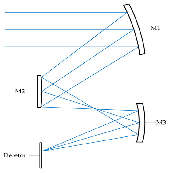
Figure 1.
A simple example of an off-axis triplex optical system.
3. Space Camera System Modeling
3.1. Optical Model
As shown in Figure 2, the large-field-of-view space camera uses an off-axis three-mirror astigmatic Cook-TMA optical system. In order to correct the wavefront aberration and distortion of the system, the primary mirror (M1) and the tertiary mirror (M3) adopt a high-order aspheric surface, and the secondary mirror (M2) adopts a quadric surface. Furthermore, the folded mirror (M4) is a plane mirror with a folding optical path, and the focal plane (FP) is the position of the detector.

Figure 2.
The optical model diagram of an off-axis three-mirror optical system.
3.2. Finite Element Model
As shown in Figure 3, the main bearing structure of the camera is mainly composed of the front frame, the back frame, and rods, which are all made of carbon fiber material. Each mirror is installed on the front/back frames of the main bearing structure through a thermal adaptive support structure. The carbon fiber front/back frames adopt a shell element with composite layup properties, the carbon fiber rods adopt a beam element with composite equivalent properties, and the rest of the structure adopts isotropic solid elements. In order to verify the influence of the gravity loading condition on the system’s Line-Of-Sight pointing, three gravity loading conditions in the direction of the optical system coordinate system were analyzed.
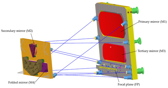
Figure 3.
The finite element model diagram of an off-axis three-mirror optical system.
4. Integrated Optomechanical Analysis of Line-Of-Sight
The analysis of Line-Of-Sight pointing errors involves many fields, such as optics, mechanics, and thermology, and it is necessary to adopt appropriate methods to establish the data transmission channels between each field [11,12]. Figure 4 shows the process of the integrated optomechanical analysis of Line-Of-Sight pointing.
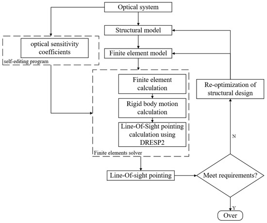
Figure 4.
Flow chart of the integrated optomechanical analysis of Line-Of-Sight pointing.
The structural finite element model of the space camera is established according to its optical system and initial structure. The optical sensitivity coefficients of the space camera are calculated according to the theory of the optomechanical constraint equations. The second type of response (DRESP2) of the Line-Of-Sight pointing to the rigid body displacement of each optical element is established. The model solution, rigid body displacement calculation, and Line-Of-Sight pointing calculation are contained within the finite element solver. The determination of whether to adjust the structural model or the structural finite element model can be made according to whether the Line-Of-Sight pointing result meets the tolerance requirements of the optical system.
4.1. Establishment and Verification of Line-Of-Sight Equations
If the perturbations are small, the higher-order optical sensitivity impacting the wavefront aberration and Line-Of-Sight pointing of the optical model is negligible, so the optical elements can be assumed to be rigid bodies. Based on the matrix of optical sensitivity coefficients and the rigid body displacements [13,14], the linear optical model can be expressed as
where k is the optical system component number. i is the number of degrees of freedom. is the optical sensitivity coefficient of optical element k in the direction of the i-th degree of freedom. is rigid body displacement of optical element k in the direction of the i-th degree of freedom.
The matrix of the optical sensitivity coefficients about the Line-Of-Sight pointing to the motion of each optical element in the image space is obtained by the optomechanical constraint equations, as shown in Table 2. Here, Δx is the motion of the optical system image along the X-axis; Δy is the motion of the optical system image along the Y-axis; MiΔx, MiΔy, MiΔz are the translation of the optical element i in three directions; Mi∆α, Mi∆β, Mi∆γ are the rotation of optical element i in three directions. i is mainly used to distinguish between optical elements.

Table 2.
The matrix of optical sensitivity coefficients calculated using the optomechanical constraint equations.
In the traditional analysis process, the calculation method of the optical sensitivity coefficients includes the addition of a small perturbation to the mirror along or around the axis of the coordinate system in the optical software and then the division of the software’s image movement output by the perturbation input to obtain the optical sensitivity coefficients [15]. This method is complicated and cannot directly obtain the optical sensitivity coefficient. Table 3 shows the matrix of optical sensitivity coefficients obtained using the above method.

Table 3.
The matrix of optical sensitivity coefficients calculated by traditional method.
The comparison of the data in Table 2 and Table 3 shows that the results are similar, which verifies the feasibility of calculating optical sensitivity coefficients using the theory of the optomechanical constraint equations. The matrix of optical sensitivity coefficients is calculated using the principle of optical imaging formula and geometric relationship and contains linear theoretical values. The traditional analysis method is based on the calculation of the output results of the optical software, and the image motion will be affected by nonlinear factors.
4.2. Static Analysis and Verification of Line-Of-Sight Stability
A single radial Line-Of-Sight error term may be calculated by vector summing the two image motion terms Δx and Δy, as illustrated in Figure 5. This method may be used to combine static error terms (i.e., pointing errors).
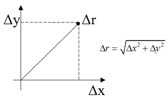
Figure 5.
Radial LOS error computed as the vector sum.
The feasibility of using the optomechanical constraint equations to calculate the optical sensitivity coefficients is verified in Section 4.1. The Line-Of-Sight equations [16,17] are established by the finite element solver card DRESP2 to conduct the Line-Of-Sight stability analysis. The response results are shown in Table 4:

Table 4.
Line-Of-Sight errors under gravity loading conditions analyzed using finite element solver.
The traditional method is to calculate the optical sensitivity coefficient of the optical system according to the output of the optical design software and then construct the LOS equation to calculate the Line-of-Sight error. The response results of the Line-Of-Sight stability analysis of the space camera under gravity loading conditions calculated using the traditional analysis method are shown in Table 5.

Table 5.
Line-Of-Sight errors under gravity loading conditions analyzed using traditional method.
The comparison of the data in Table 4 and Table 5 shows that the Line-Of-Sight errors under gravity loading conditions in the X-, Y-, and Z-direction are approximately the same, and the Line-Of-Sight error under the gravity condition in the X-direction is larger. The main reasons for the slight differences between the two methods are as follows: (1) The methods used to calculate the optical sensitivity coefficients are different, resulting in a slight difference in the calculation results. (2) There are differences between the two methods used to calculate rigid body motions [18,19].
The optical element that contributes the most to the Line-Of-Sight error can be determined by analyzing the translational error components and the rotational error components generated by each optical element in the image space. Figure 6 and Figure 7 contain drawings of the translation and rotation components of the Line-Of-Sight error for each optical element examined under gravity loading conditions in three directions. From Figure 6, it can be seen that the translational error of the secondary mirror under the X-direction and Y-direction gravity loading conditions, respectively, contributes significantly to the Line-Of-Sight error. From Figure 7, the rotation error of the secondary mirror around the Y-axis under the X-direction gravity loading condition contributes significantly to the Line-Of-Sight error, and the rotation error of the folding mirror around the X-axis under the Z-direction gravity loading condition also contributes significantly to the Line-Of-Sight error. It can be determined that the secondary mirror is the optical element that contributes the most to the Line-Of-Sight error, which provides a reference for the subsequent structural optimization and assembly of these space cameras.
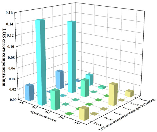
Figure 6.
Line-Of-Sight error components caused by the translation of each optical element under gravity loading conditions in three directions.
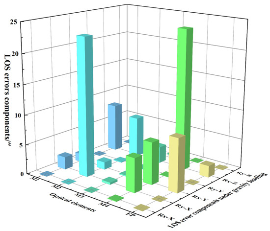
Figure 7.
Line-Of-Sight error components caused by the rotation of each optical element under gravity loading conditions in three directions.
In Figure 6 and Figure 7, the static LOS error components of each optical element are displayed under different gravity loading conditions, which is convenient for analyzing which are the sensitive optical elements and facilitating the optimization of the system’s structure. The X-axis represents each optical element of the off-axis three-mirror space camera (M1, M2, M3, M4, FP). The Y-axis represents the X-direction and Y-direction translation and rotation (Tx-X, Ty-X, Tx-Y, Ty-Y, Tx-Z, Ty-Z, and so on) of each optical element under three gravity loading conditions. Tx-X represents the translational motion of the optical element in the X-direction under the gravity loading condition in the X-direction. The Z-axis represents the LOS error components.
5. Discussion
The integrated analysis method of Line-Of-Sight stability based on the optomechanical constraint equations can effectively analyze the sensitive loading environment and the sensitive optical elements of the space camera. The feasibility and accuracy of this method are also verified by comparing it with traditional methods. Based on the results, the following discussion is summarized, and future research is envisaged.
The error of the Line-Of-Sight stability calculation results using this method is less than 6.38% relative to those obtained from traditional methods.
The optomechanical constraint equations allow optical theory to be applied to structural models for optomechanical integration. However, the stability analysis of Line-Of-Sight in the current paper adopts the spherical radius to simulate the effect of the change in the vertex curvature radius on the mirror node displacement, missing the description of the linear relationship between the change in the vertex curvature radius and the mirror node displacement directly. This linear relationship should be considered in later stages for face shape analysis.
In this paper, DRESP2 is used for integrated Line-Of-Sight stability analysis at the finite element solver level. To improve evaluation speed, DRESP3 can be utilized to construct code for optomechanical constraint equations and compute optical sensitivity coefficients directly into finite element solvers for more rapid and effective evaluation.
A comprehensive optical, mechanical, and thermal analysis should be performed. For a more detailed analysis, mechanically and thermally induced changes in Line-Of-Sight stability will be fully considered in subsequent studies. The methodology of this paper can also be used for dynamic environmental space camera Line-Of-Sight stability analysis and optical system structure optimization. Thus, the integration of optomechanical at the level of linear finite element solvers is closer to real structural analysis.
6. Conclusions
The motions of optical elements caused by gravity will affect the pointing accuracy of space cameras. In this paper, an off-axis three-mirror optical system is taken as the research object, and an optomechanical integration method is proposed for assessing Line-Of-Sight stability based on the optical sensitivity calculation of the optomechanical constraint equations in the finite element solver level. This method can effectively analyze the Line-Of-Sight stability of complex optical systems. Through the analysis of the static characteristics of the space camera, the most sensitive optical element was found to be the secondary mirror, and the sensitive motion state is its rotation around the Y-axis of the lens in the X-direction gravity loading condition, its translation along the X-axis of the lens in the X-direction gravity loading condition, and its translation along the X-axis of the lens in the Y-direction gravity loading condition. The X-direction gravity loading condition has the greatest influence on all optical elements. These conclusions are consistent with the comparative verification results, demonstrating the effectiveness of this method of analysis. The feedback sensitivity matrix of the Line-Of-Sight stability analysis method proposed in this paper has significance as a reference for the online evaluation and topology optimization of the system-level optical performance of space cameras in static and dynamic environments.
Author Contributions
Conceptualization, Y.L. and S.W.; methodology, Y.L.; software, Y.L.; validation, Y.L. and B.S.; formal analysis, Y.L. and G.M.; investigation, S.W. and Y.L.; resources, S.W. and Q.Z.; data curation, S.W. and B.S.; writing—original draft preparation, Y.L.; writing—review and editing, S.W.; visualization, Y.L.; supervision, S.W. and G.M.; project administration, Y.G. and Z.W.; funding acquisition, S.W. All authors have read and agreed to the published version of the manuscript.
Funding
Please add: This research was funded by the National Natural Science Foundation of China (11873046).
Institutional Review Board Statement
Not applicable.
Informed Consent Statement
Not applicable.
Data Availability Statement
The data underlying the results presented in this study are not currently publicly available but may be obtained from the corresponding authors upon request.
Conflicts of Interest
The authors declare no conflicts of interest.
References
- Bao, Q.H. Lineweight and Optimization Design and Research for the Opto-Mechanical Structure of Off-Axis Space Camera; Changchun Institute of Optics, Fine Mechanics and Physics, Chinese Academy of Sciences: Changchun, China, 2016. [Google Scholar]
- Koppen, S.; Van Der Kolk, M.; Van Kempen, F.C.M.; De Vreugd, J.; Langelaar, M. Topology optimization of multicomponent optomechanical systems for improved optical performance. Struct. Multidiscip. Optim. 2018, 58, 885–901. [Google Scholar] [CrossRef]
- Hu, M.; Pan, Y.; Zhang, N.; Xu, X. A Review on Zernike Coefficient-Solving Algorithms (CSAs) Used for Integrated Optomechanical Analysis (IOA). Photonics 2023, 10, 177. [Google Scholar] [CrossRef]
- Takanori, T. Precision attitude and position determination for the Advanced Land Observing Satellite (ALOS). Enabling Sens. Platf. Technol. Spaceborne Remote Sens. 2005, 5659, 34–50. [Google Scholar]
- Gao, H.T.; Luo, W.B.; Shi, H.T.; Mo, F.; Li, S.H.; Zhang, X.W.; Liu, X.G.; Cao, G.Y. Structural Stability Design and Implementation of ZY-3 Satellite. Spacecr. Eng. 2016, 25, 18–24. [Google Scholar]
- Gong, D.; Tian, T.Y.; Wang, H. Computer-aided alignment of off-axis three-mirror system by using Zernike coefficients. Opt. Precis. Eng. 2010, 18, 1754–1759. [Google Scholar]
- Yang, Y.S.; Zhao, Q.; Wang, J.L.; Liu, J.; Wang, P. Optical Axis Stability Modeling and Analysis of Infrared Optical System. Electron. Opt. Control 2017, 24, 81–84. [Google Scholar]
- Burge, J.H. An easy way to relate optical element motion to system pointing stability. Level of Thesis, Degree-Granting University, Location of University, Date of Completion. Curr. Dev. Lens Des. Opt. Eng. VII 2006, 6288, 168–179. [Google Scholar]
- Hatheway, A.E. The Optomechanical Constraint Equations: Theory and Applications; SPIE Press: San Diego, CA, USA, 2016; pp. 19–39. [Google Scholar]
- Anees, A. Handbook of Optomechanical Engineering; CRC Press: Boca Raton, FL, USA, 2017; pp. 412–429. [Google Scholar]
- Cheng, X.; Liu, C. Optical and Mechanical Performance and Feasibility Analysis of Meter-Level Corrector Lenses for Survey Telescope. Photonics 2023, 10, 422. [Google Scholar] [CrossRef]
- Liu, J.; Xue, J.; Ren, J.Y. Review of Research on Integration Design of Structural, Thermal and Optical Analysis with Key Technique of Space Camera. J. Astronaut. 2009, 30, 422–427+480. [Google Scholar]
- Zhang, C.; Xing, H.; Song, J.R.; Yan, J.H.; Zhang, K.; Li, C.Y.; Liu, Z.Y.; Jin, Z.R. Measurement of optical axis eccentricity of a large-aperture concave ellipsoid mirror. Infrared Laser Eng. 2021, 50, 12. [Google Scholar]
- Liu, Y.; Tang, T.J.; Wang, Q.X.; Jiang, Y.H.; Hu, Y.L. Research on decomposition method of camera LOS thermal stability index based on Monte Carlo method. Infrared Laser Eng. 2023, 52, 12. [Google Scholar]
- Li, X.Y.; Li, Y.C.; Ma, Z.; Yi, H.W. Computer-aided alignment method of coaxial three-mirror-anastigmat system. J. Appl. Opt. 2009, 30, 6. [Google Scholar]
- Genberg, V.L.; Michels, G.J.; Doyle, K.B. Integrated modeling of jitter MTF due to random loads. Opt. Model. Perform. Predict. V SPIE 2011, 8127, 157–165. [Google Scholar]
- Doyle, K.B.; Victor, L.G.; Gregory, J.M. Integrated Optomechanical Analysis, 2nd ed.; SPIE Press: San Diego, CA, USA, 2002; pp. 178–183. [Google Scholar]
- Zhang, Y.; Ding, Z.M.; Zhao, H.J.; Zou, B.Y. Rigid-body displacement separation of optics in optical-structural-thermal integrated analysis. Infrared Laser Eng. 2012, 41, 2763–2767. [Google Scholar]
- Zeng, C.F.; Ouyang, Y.G. Research on Optical Axis Stability of Optical System Based on Thermal-Structural-Optical Integrated Analysis. Opt. Optoelectron. Technol. 2021, 19, 50–56. [Google Scholar]
Disclaimer/Publisher’s Note: The statements, opinions and data contained in all publications are solely those of the individual author(s) and contributor(s) and not of MDPI and/or the editor(s). MDPI and/or the editor(s) disclaim responsibility for any injury to people or property resulting from any ideas, methods, instructions or products referred to in the content. |
© 2024 by the authors. Licensee MDPI, Basel, Switzerland. This article is an open access article distributed under the terms and conditions of the Creative Commons Attribution (CC BY) license (https://creativecommons.org/licenses/by/4.0/).