Article

Double-Cycle Alternating-Flow Diode Pumped Potassium Vapor Laser

1
Aerospace Information Research Institute, Chinese Academy of Sciences, Beijing 100094, China
2
University of Chinese Academy of Sciences (UCAS), Beijing 100049, China
*
Author to whom correspondence should be addressed.
Photonics 2024, 11(5), 391; https://doi.org/10.3390/photonics11050391
Submission received: 28 March 2024 / Revised: 7 April 2024 / Accepted: 22 April 2024 / Published: 23 April 2024

Abstract

:
A novel double-cycle alternating-flow diode-pumped potassium vapor laser is proposed, theoretically modeled and simulated. The results show that the optical-to-optical efficiency of the laser increases with increasing gas flow rates, although at high flow rates the rate of increase in efficiency decreases. The optical-to-optical efficiency reaches 74.8% at a pump power density of 30 kW/cm2 and a gas flow rate of 50 m/s. The optical-to-optical efficiency of the laser is greater with a narrow linewidth pump and high buffer gas pressure. The optical-to-optical efficiency of a flow gas cell is higher than that of a static gas cell. There is an optimal gas cell length that provides the highest optical-to-optical efficiency. At higher pump power densities, higher flow rates are required to obtain higher optical-to-optical efficiencies.

1. Introduction

The diode-pumped alkali vapor laser (DPAL) is a new type of optically pumped gas laser with extremely high quantum efficiency. It is a type of laser system with the potential to provide single-aperture MW-class average power output. Since it was first proposed at Lawrence Livermore National Laboratory in 2003 [1], DPALs have been rapidly developed to increase their advantages and potential applications. The gain medium of DPALs is a gaseous alkali metal, usually potassium (K), rubidium (Rb), or cesium (Cs). Compared with rubidium and cesium, potassium vapor lasers (K-DPAL) have the following advantages: Firstly, their quantum efficiency can reach 99.5%, compared with 98.11% and 95.2% for their rubidium and cesium equivalents, respectively. Secondly, they can provide alkane-free operation, which avoids contamination by carbon particles caused by the high-temperature reaction of alkali metals with alkane-based gases. Therefore, K-DPALs have great potential for high power output.
Theoretically, in 2012, Barmashenko et al. from Gurion University, Israel, developed a simplified semi-analytical flow DPAL model [2] without considering the quenching of the electronic states of alkali metal atoms, ionization, and higher energy level leaps, which simulated the gas flow and output lasing relationship [3,4]. The results show that the assumption of the semi-analytical model for the uniform distribution of different material densities and temperatures in the laser region is inaccurate, so the group further proposes a two-dimensional/three-dimensional computational fluid dynamics model (2D/3DCFD) [4,5,6]. For low pump powers, the laser powers predicted by the two models are very close to each other; however, at higher pump powers, the laser powers calculated using the 2D/3DCFD model are much higher than those calculated using the semi-analytical model. The group used the two models to theoretically analyze the effects of gas flow rate, buffer gas composition, pumping mode, flow mode and other parameters on the output laser performance and found that gas flow mode, pumping mode and buffer gas composition have a significant effect on the output performance of the circulating flow-type DPAL.
In 2013, the group first proposed the supersonic DPAL model [7] to obtain the temperature and alkali metal atomic concentration favorable for pump absorption. It was found that for the long-term continuous operation of supersonic DPAL, cyclic operation is required to save gas [8]. Subsequent comparison of the output performance of K-DPAL and Cs-DPAL at supersonic, subsonic, and transonic speeds [9,10,11,12] reveals that supersonic speeds are superior to transonic speeds, and transonic speeds are superior to subsonic speeds, while the maximum output power of K-DPAL is higher than that of supersonic Cs-DPAL at supersonic speeds [13,14]. In order to realize high-pressure and high-speed gas flow, ultra-high-power mechanical pumps are required, which is the key to the long-term continuous operation of supersonic recirculating flow-type DPAL.
In 2018, Gavrielides et al. at the U.S. Air Force Institute of Technology [15,16] systematically investigated the effect of the flow mode on the far-field beam quality, and the results showed that the beam quality of circulating-flow type DPAL was better in the case of transverse flow of gas relative to that in the case of axial flow, which was in agreement with the conclusion of Gurion University.
In 2018, Endo et al. from Tokai University, Japan, numerically simulated the circulating flow-type DPAL using a fluctuating optical resonant cavity model to simplify the thermal lensing effect in the case of gas flow [17]. The model correctly predicted the temperature distribution of the gain medium and the calculated values were in good agreement with the experimental values, but it was only applicable to forced-flow DPALs. In 2020, the group proposed an incompressible 3D-CFD model [18]. The modified Boussinesq approximation was used to simulate the natural convective flow, and the model can accurately calculate the flow field distribution of DPAL and agrees well with the experimental results.
Experimentally, in 2013, the Livermore Lawrence Laboratory in the U.S. realized the first circulating flow-type DPAL laser output at several kW level, and the circulating flow-type DPAL output power reached 4 kW by increasing the size of the vapor cell and improving the optics, optical coatings, and the window of the vapor cell. In 2015, the group effectively controlled the working gas temperature to achieve 13 kW of laser output [19,20].
In 2015, the first circulating flow type K-DPAL laser output was realized by Zhdanov’s group at the U.S. Air Force Academy Laboratory [21]. The circulating flow system consists of a magnetically driven gas blower, a reservoir for alkali metal vapors, a gas handling system for filling as well as discharging the vapors, and a vapor pool. All system components and connecting tubes are made of alkali-resistant stainless steel. The steam cell has four windows with an alkali-resistant anti-reflective coating on both sides for end and side pumping. With end-face pumping, the gas flow direction is perpendicular to the laser and pump axes, which reduces turbulence in the gain region. The buffer gas pressure is 800 torr, the flow rate is 6.6 m/s, the temperature of the alkali metal vapor cell is 180 °C, and the maximum laser output power is 5 W with a pump power of 40 W, with a slope efficiency of 31%.
In 2016, the group continued to explore the effect of gas flow rate on the power of circulating flow type DPAL. Comparing the output power of Cs-DPAL and K-DPAL with and without gas flow under low gas pressure in the vapor cell [22], the experimental results show that the larger the gas flow rate, the DPAL peak power and continuous power increase, and the attenuation of power with time increases is smaller. When the gas flow rate increases from 0 to 6 m/s, the attenuation of K-DPAL output power decreases from 60% to 40%. For Cs-DPAL, this difference decreases from 20% at 1 m/s to 3% at 4 m/s. This suggests that the power of K-DPAL output decreases from 60% to 40% in continuous wave mode. This shows that in continuous-wave mode, a higher gas flow rate can mitigate the gas thermal effect in time to suppress the downward trend of laser power. Even in the case of imperfect mode matching, the K-DPAL slope efficiency is still 30% higher when the gas is flowing than when the gas is stationary. In addition, Zhdanov and Knize compared the performance of K-DPAL and Cs-DPAL. The Cs-DPAL system has a higher gain and lower threshold than K-DPAL. However, Cs-DPAL requires alkanes as buffer gases, which tend to chemically react with Cs at higher temperatures, reducing Cs-DPAL output performance. K-DPAL, on the other hand, can realize laser output without hydrocarbons. However, K-DPAL requires high pumping intensity due to its relatively low gain, which may cause strong thermal effects on the gas. Since the thermal effect can be mitigated by using a high-speed recirculating flow method, the recirculating flow K-DPAL is expected to realize high-power and high-efficiency laser output, as is the case for the Cs-DPAL. Currently, thermal management is the key challenge limiting the power of K-DPALs. The gain medium of K-DPAL is potassium, which has a high threshold. To generate high power, a high potassium vapor density is required, creating temperatures of >200 °C. Such high temperatures and the waste heat generated by the high-energy-level spontaneous radiation of potassium atoms have severe thermal effects on the gas inside the vapor cell, degrading the DPAL’s output.
In this paper, a novel double-cycle alternating-flow diode-pumped potassium vapor laser is proposed. It controls the potassium and high-temperature regions in the gain zone to reduce thermal effects.

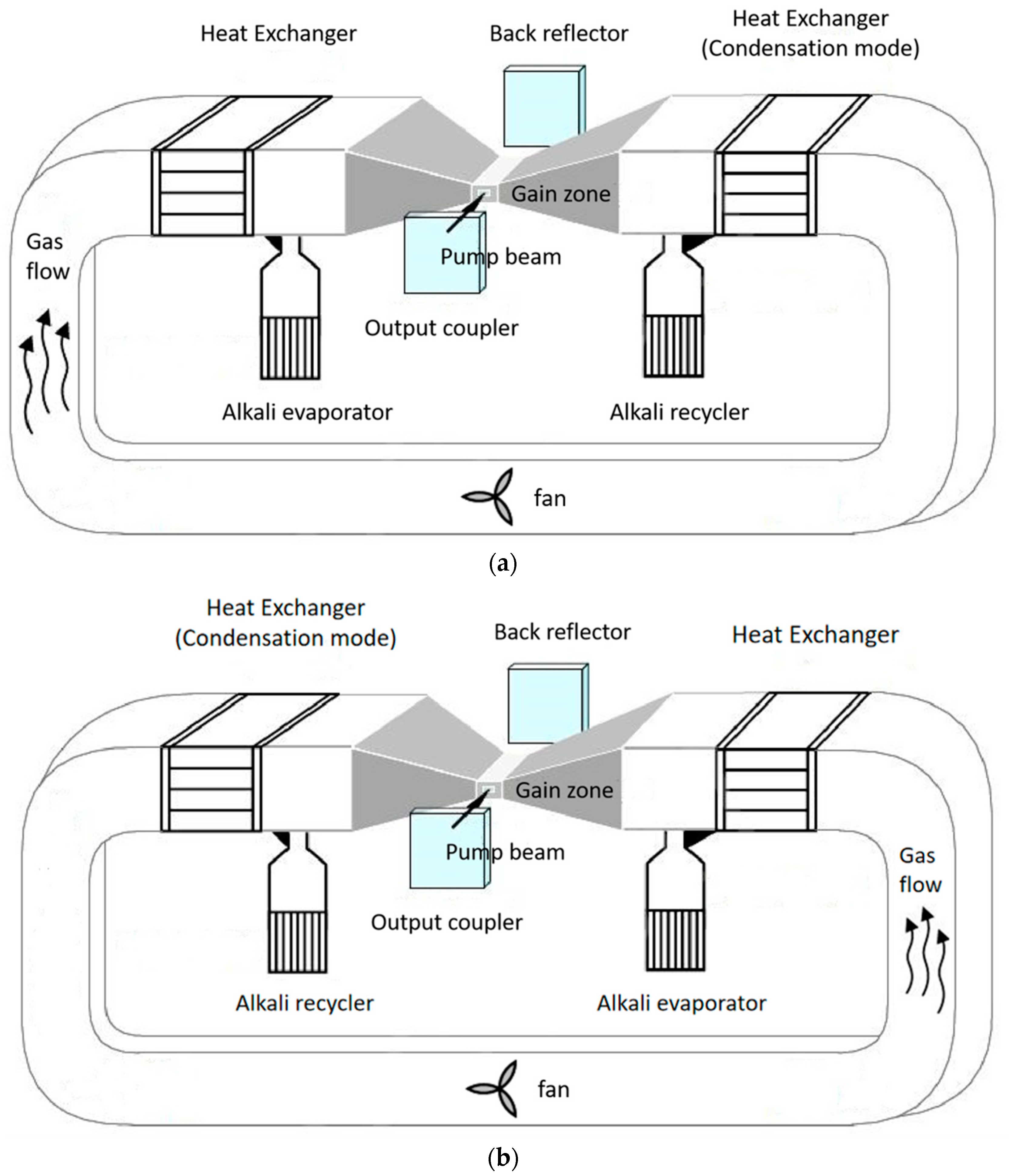
2. Description of the Novel DPAL

Figure 1 shows a schematic diagram of the double-cycle alternating-flow diode-pumped potassium vapor laser. Helium is pre-filled throughout the device as a buffer gas. The device is operated in an alternating cycle, where only the gas flow direction and the operating state of some of the devices are different. The working cycle shown in Figure 1a has a clockwise gas flow. After the helium buffer gas passes through the heat exchanger, the gas temperature increases to operating temperature T in the DPAL gain zone. At the same time, the gas is mixed with potassium atoms produced by the evaporator and enters the DPAL gain zone. Then the potassium atoms are pumped, generating particle number inversion between energy levels, and laser output is achieved. After the gas flows through the gain zone, it reaches the right-side heat exchanger, which cools the working state and reduces the gas temperature. Then, potassium atoms are condensed and returned to the alkali recycler. The set temperature of the condenser is decided according to the measured condensation efficiency. The working cycle ends when there is little-to-no potassium remaining in the left-side alkali evaporator. In the next working cycle (Figure 1b), the gas flows counterclockwise. The roles of the two heat exchangers are swapped so that the potassium atoms collected in the right-side alkali evaporator are gradually returned to the left one after passing through the gain zone, achieving a complete working cycle.
In the proposed laser, potassium vapor flows between evaporation and condensation processes in a localized small circuit. The buffer gas flows throughout the cavity in a closed major circuit. The two circulation flow paths only overlap near the gain zone. The gas flow alternates clockwise and counterclockwise. Potassium vapor produced by the evaporator is fully condensed after passing through the gain zone with the gas flow to the heat exchanger on the other side. Most of the atoms are converted from a gaseous state to a liquid state and flow back into the evaporator. Previous flow-based DPALs have maintained a high temperature throughout the flow channel through which alkali vapor and buffer gas flow. In this paper, most of the potassium atoms are confined between the sides of the gain zone, which greatly reduces contamination of the whole device by alkali atoms and increases the range of housing materials that can be used. Moreover, the use of double heat exchangers only necessitates a high temperature of about 200 °C near the gain zone of the DPAL. The temperatures in other zones can be lower, even at room temperature, which reduces the requirements for vacuum heat resistance and cavity insulation.
A theoretical model of the laser was established using an end pump. The schematic diagram is shown in Figure 2. The blue and red line represent the pump and the laser, respectively. The change in flow direction over time is not taken into account in the following calculations because it does not change the optical-to-optical efficiency of the laser output. The pump and laser beam intensities are uniform across the beam cross section. The pump light is injected into the resonant cavity through the PBS and passes through the gain medium from left to right, generating particle number inversion and laser output. The parameters shown in the figure are defined in Table 1.
The K-DPAL is a three-level system. The three-level rate equations are as follows:
d n 1 z d t = n 1 z 1 2 n 3 z × 0 σ 13 ν I p z , ν h v p d ν + n 2 z n 1 z σ 21 I l + z + I l z h v l + n 2 z τ 21 + n 3 z τ 31
d n 2 z d t = n 2 z n 1 z σ 21 I l + z + I l z h v l + γ m i x n 3 z 2 exp E k T n 2 z n 2 z τ 21
d n 3 z d t = n 1 z 1 2 n 3 z × 0 σ 13 ν I p z , ν h v p d ν γ m i x n 3 z 2 exp E k T n 2 z n 3 z τ 31
where n 1 , n 2 , and n 3 are the population densities of particles at energy levels S 1 / 2 2 , P 1 / 2 2 , and P 3 / 2 2 , respectively. I l ± are the forward and backward laser power densities in the gain zone, and T is the gain zone temperature.
σ 13 ν is the stimulated absorption cross section:
σ 13 ν = f 3 f 1 c 2 8 π τ 31 ν D 2 2
where ν D 2 is the center frequency of the potassium atomic absorption, f 3 and f 1 are the statistical weights of energy levels P 3 / 2 2 and P 1 / 2 2 , respectively.
γ m i x is the fine-structure mixing rate:
γ m i x = n H e σ 32 v r
v r = 3 k T 1 m H e + 1 m K 1 2
where σ 32 is the mixing cross section, n H e is the helium population density and v r is the thermally averaged relative velocity of helium to potassium.
The total population density of potassium vapor is obtained by the following equations [23]:
log ( n t o t k T ) = 9.408 4453 / T
n 1 z + n 2 z + n 3 z = n t o t z .
The propagation intensities of the pump and the laser in the gain zone are expressed by the following equations:
I p z + z , ν = I p z , ν exp n 1 z 1 2 n 3 z σ 13 ν z .
I l ± z + z = I l ± z exp ± n 2 z n 1 z σ 21 z .
The heat dissipation of the gas in the lateral flow condition [24] is:
R h e a t = 2 π ω l l u N w N A T w T C p T d t + 2 π ω l k T N u T T w
where l is the gain length of the vapor cell, u is the gas flow rate, k is the thermal conductivity of the gas, T is the temperature of the gas in the vapor cell, Tw is the temperature of the wall of the vapor cell, ω l is the radius of the laser spot, Nw is the concentration of working gas particles at the sidewalls of the vapor cell, NA is Avogadro’s constant, Cp(T) is the total molar heat capacity of the buffer gas, k(T) is the total thermal conductivity of the buffer gas, and Nu is the Nusselt number.
The waste heat generated during steady-state operation of the DPAL [18] can be expressed as:
P w a s t e = 0 l γ 32 n 3 2 n 2 exp E / k B T E + h ( ν 21 Q 21 + ν 31 Q 31 ) d z
where the first term on the right-hand side of the equation is the waste heat generated by the relaxation of the P 3 / 2 2 energy level to the P 1 / 2 2 energy level, and the second term is the waste heat generated by the radiation-free jump to the ground state of the P 1 / 2 2   P 3 / 2 2 energy levels.
When the heat is in equilibrium, heat production equals heat dissipation:
R h e a t = P w a s t e
The laser’s output power is calculated as follows: Assume that the initial laser light intensity is 0 and that the initial temperature of the gas in the gain zone and the pump power density are known. The calculation process is shown in Figure 3.
(a)
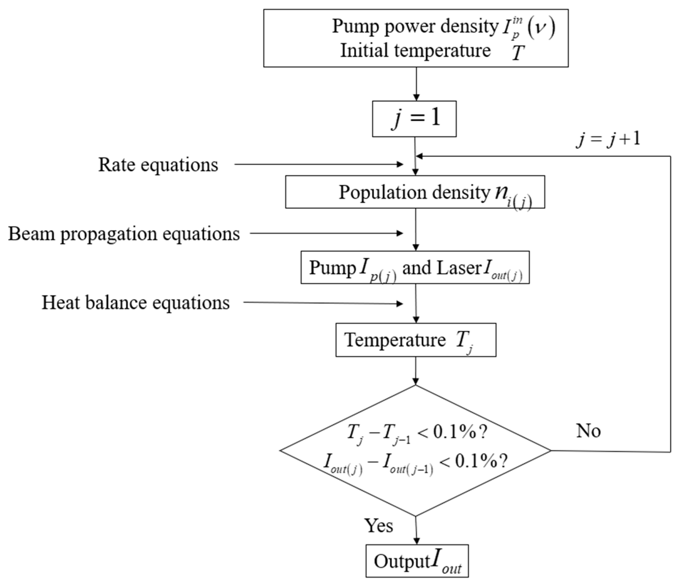
Solve the rate Equations (1)–(3) to obtain the population density of K atoms at each energy level;
(b)
Substitute K into the beam propagation Equations (7) and (8) to obtain the initial distribution of the pump and laser in the resonant cavity;
(c)
Solve the heat balance Equation (13) to obtain the temperature in the gain zone;
(d)
Use the obtained temperature instead of the initial temperature to correct the parameters affected by temperature, then re-substitute these parameters into the rate equation and beam propagation equation to solve the new atomic population density K of each energy level and the distribution of the pump and laser;
(e)
Repeat Steps (b)–(d) until the temperature and laser amplitude in the gain zone stabilize; finally, obtain the laser output in the steady state.

3. Results and Discussion
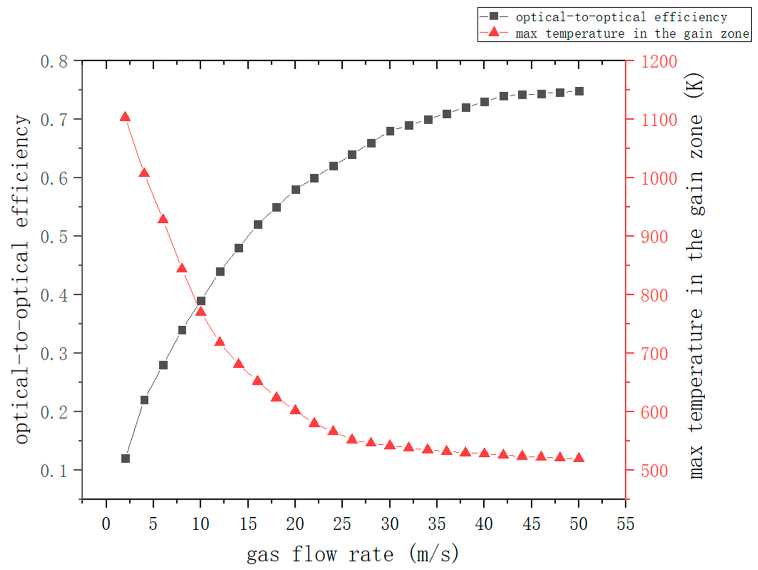
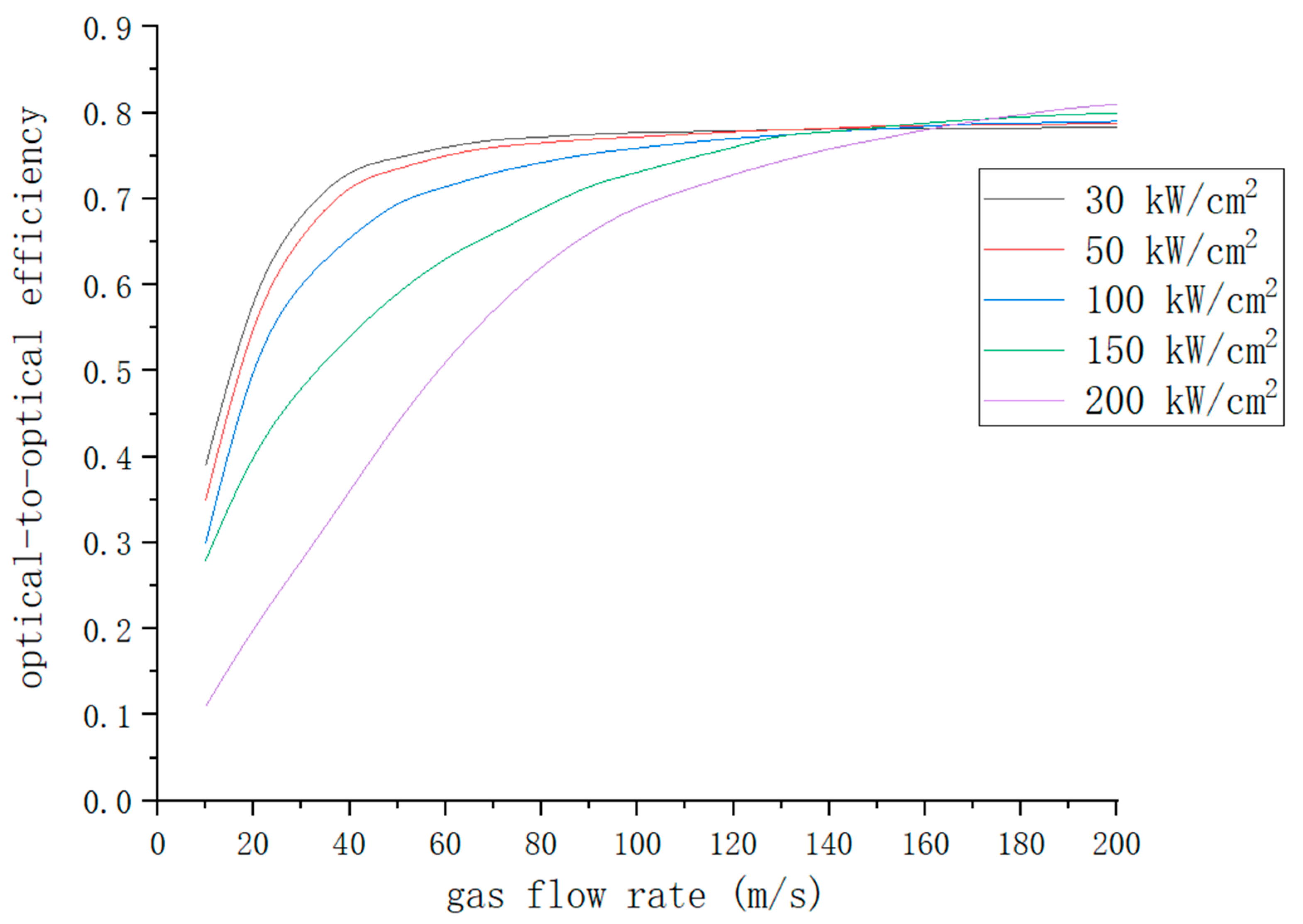
3.1. Gas Flow Rate

Assume that the pump’s center wavelength is 766.5 nm, the linewidth of the pump is 0.1 nm, the pump’s power density is 30 kW/cm2, the length of gain zone l is 1 cm, and the helium pressure is 600 torr. Then, the dependence of the optical-to-optical efficiency and maximum gain zone temperature on the gas flow rate can be calculated (Figure 4).
In Figure 4, at gas flow rates < 20 m/s, the optical-to-optical efficiency increases rapidly with the flow rate. The optical-to-optical efficiency is 12.2% at a gas flow rate of 2 m/s and reaches 66.3% at 20 m/s. At gas flow rates > 20 m/s, the optical-to-optical efficiency increases more gradually. The optical-to-optical efficiency is 74.8% at a gas flow rate of 50 m/s. The maximum temperature in the gain zone changes in the opposite direction, reaching temperatures of 602.4 K and 520.5 K at gas flow rates of 20 m/s and 50 m/s, respectively. This indicates that higher gas flow rates correspond to higher photoluminescence efficiency and lower maximum temperatures in the gain zone.

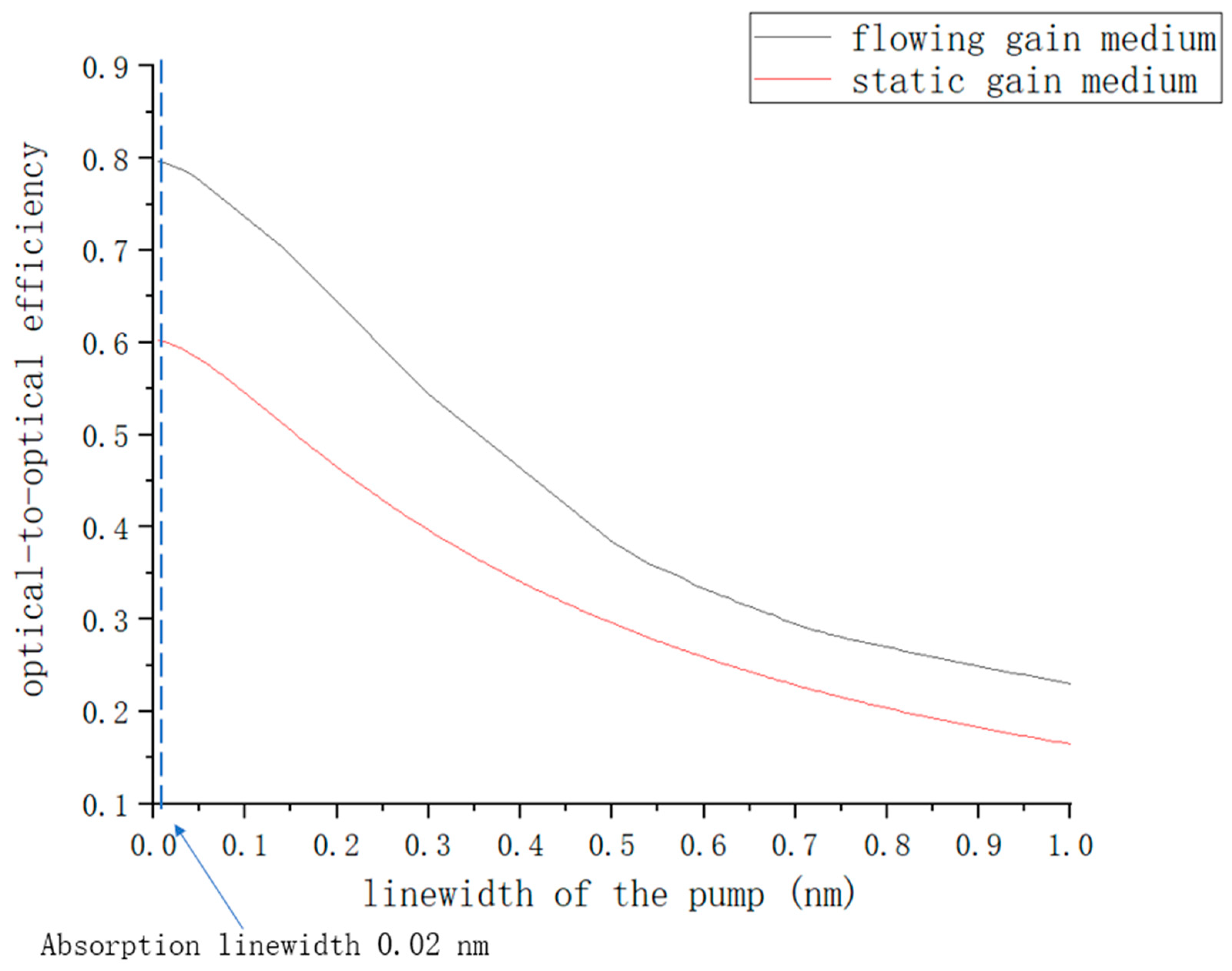
3.2. Linewidth of the Pump

Using the parameters in Section 3.1, the effect of pump linewidth on laser output characteristics is analyzed at a gas flow rate of 50 m/s. The model of the static gain medium is taken from [18]. The results are shown in Figure 5.
Figure 5 shows that when the pump linewidth is narrower, the pump’s spectral line shape matches well with the broadened alkali D2 spectral line. The pump absorption is high, so there will be a higher optical-to-optical efficiency. When the pump linewidth is 0.02 nm, the optical-to-optical efficiency of the flowing gain medium is 79.2%, which is optimal. At higher linewidths, the matching effect decreases and pump absorption decreases, resulting in lower optical-to-optical efficiency. At a linewidth of 0.5 nm, the flowing and static gain media have only 38.4% and 29.8% optical-to-optical efficiencies, respectively. At a pump linewidth of 0.1 nm, the optical-to-optical efficiency is 73.6%, which is 92.9% of the optimal value. A 0.1 nm linewidth was easily achieved by the LD pump source in the experiments, so the linewidths used in the simulations were all set to 0.1 nm. At the same time, regardless of pump line width, the optical-to-optical efficiencies of the flowing gain medium were higher than those of the static gain medium.

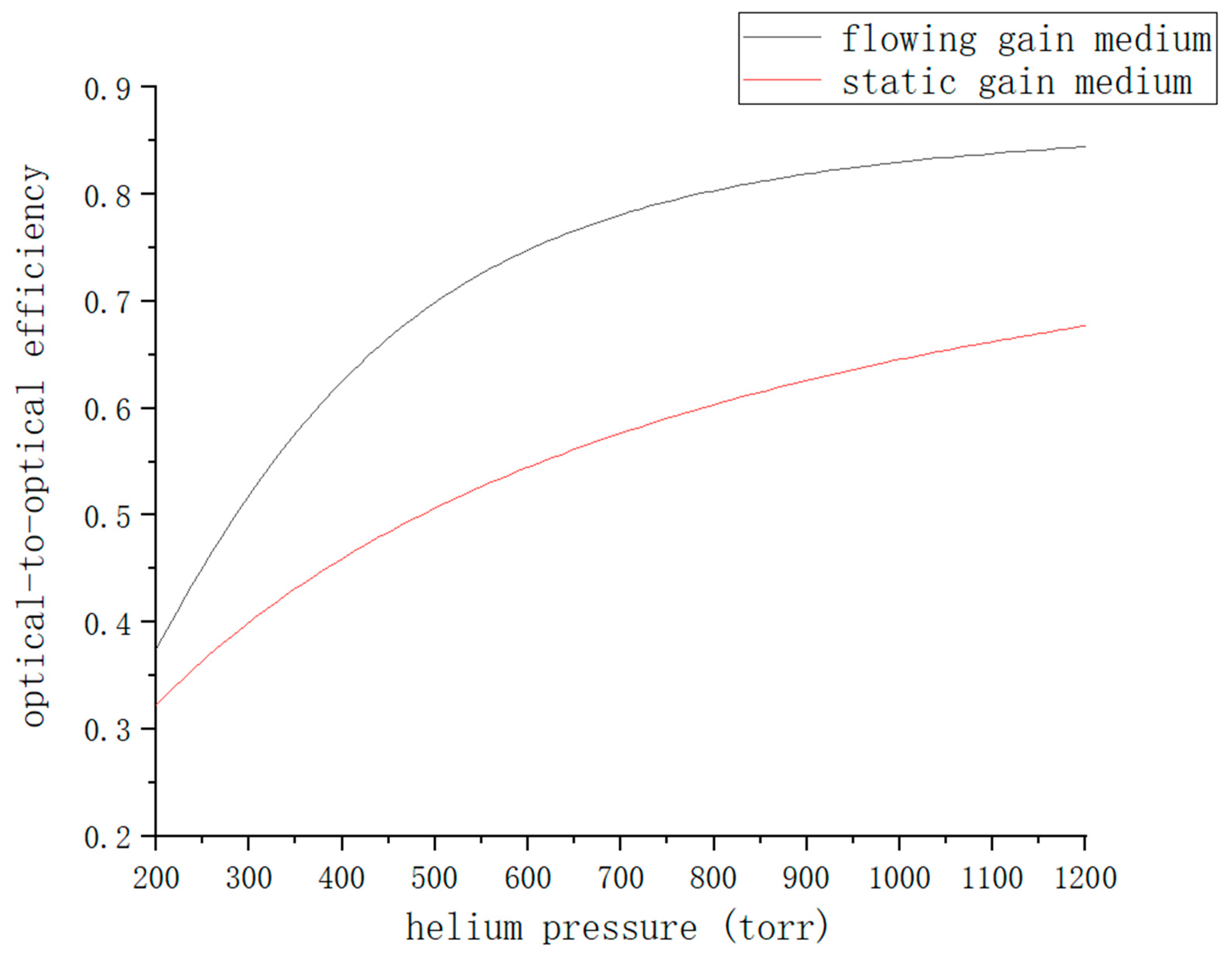
3.3. Helium Pressure

The parameters in Section 3.1 were used to analyze the effect of helium pressure on the laser output characteristics at a gas flow rate of 50 m/s (Figure 6).
Figure 6 shows that the optical-to-optical efficiency increases with helium pressure, first rapidly and then slowly. At helium pressures of 200 torr, 600 torr, and 1000 torr, the optical-to-optical efficiencies of the flowing gain medium are 37.5%, 74.8%, and 83.0%, respectively, while those of the static gain medium are 32.3%, 54.5%, and 64.6%. The reason is that when the helium pressure is low, an increase in pressure broadens the alkali D1 and D2 lines, increases the relaxation rate of the fine structure, accelerates the laser conversion rate, and increases the output power. However, with further increases in helium pressure, the fine structure relaxation rate gradually tends toward saturation, and the increase in laser output power slows down. In addition, the optical-to-optical efficiency of the flowing gain medium is greater than that of the static gain medium because the gas flow dissipates the heat deposited in the gain medium, which improves the conversion efficiency of the pump.

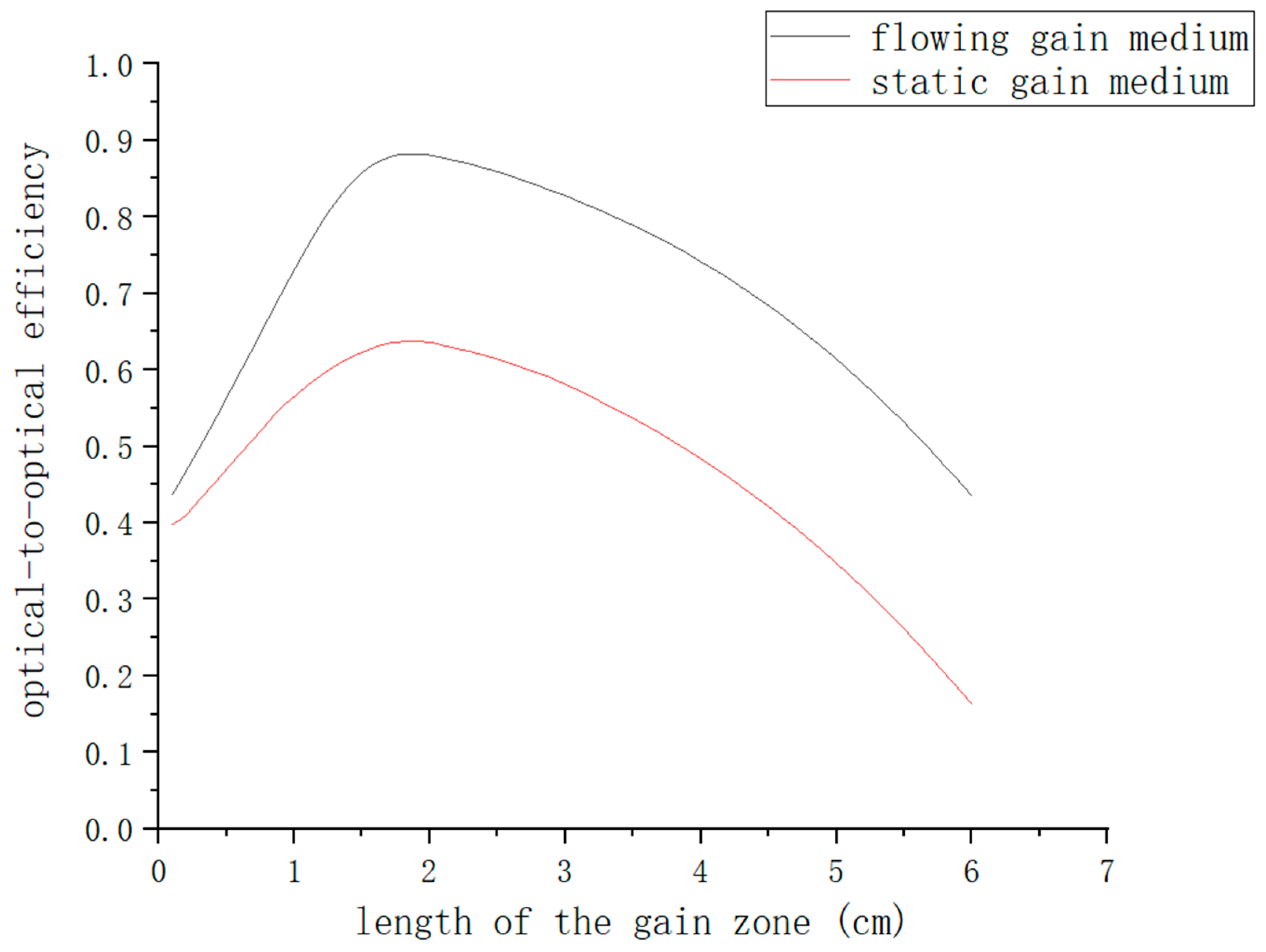
3.4. Length of the Gain Zone

The parameters in Section 3.1 were used to analyze the effect of gain zone length on the laser output characteristics at a gas flow rate of 50 m/s (Figure 7).
In Figure 7, a short gain zone length causes the pump to be ejected from the other end of the gain zone before it is fully absorbed. So the gain zone has low absorption of the pump, resulting in low optical-to-optical efficiency. When the length of the gain zone is 0.2 cm, the optical-to-optical efficiencies of the flowing and static gain media are 46.7% and 41.0%, respectively. As the gain zone length increases, the pump is absorbed sufficiently and the optical-to-optical efficiency increases. At a length of 2 cm, the optical-to-optical efficiencies of the flowing and static gain media are 88.2% and 63.7%, respectively. As the length is further increased, the pump is fully absorbed before passing through the gain zone. The laser gains only in the zone where the pump is absorbed, not where it is not absorbed. It is also absorbed by the potassium vapor, which generates waste heat deposition and decreases the optical-to-optical efficiency. At a gain zone length of 6 cm, the optical-to-optical efficiencies of the flowing and static gain media are 43.5% and 16.3%, respectively. There is less power decrease in the flowing gain medium than in the static gain medium because the gas flow dissipates some of the heat.

3.5. Pump Power Density

In Section 3.1, we only considered a case with a pump power density of 30 kW/cm2. The effect of gas flow rate on laser output characteristics was then analyzed under an increasing pump power density (Figure 8).
In Figure 8, at low gas flow rates, the optical-to-optical efficiencies are lower for higher pump power densities because higher densities produce more heat, which lower flow rates are unable to dissipate. As the gas flow rate increases, the optical-to-optical efficiency begins to improve. At a flow rate of 50 m/s, the optical-to-optical efficiencies are 74.8% and 73.5% at pump power densities of 30 kW/cm2 and 50 kW/cm2, respectively. As the flow rate continues to increase, their optical-to-optical efficiencies increase very little and reach a plateau. At a pump power density of 100 kW/cm2, the optical-to-optical efficiency plateaus at a flow rate of 120 m/s, which is 77.0%. At 150 kW/cm2, the efficiency plateaus at a flow rate of 160 m/s, which is 78.8%. At 200 kW/cm2, the efficiency is 81.0% at a flow rate of 200 m/s, showing that there is a minor upward trend. It can be seen that at higher pump power densities, higher gas flow rates are required to obtain high optical-to-optical efficiencies.

4. Conclusions

In this paper, a novel double-cycle alternating-flow diode-pumped potassium vapor laser is proposed to solve the thermal management problems faced by DPALs. Based on three-level rate equations, the end-pumped potassium laser was modeled and its output characteristics investigated. The results show that the optical-to-optical efficiency of the laser increases with the gas flow rate, first rapidly and then slowly. The optical-to-optical efficiency is 74.8% at a gas flow rate of 50 m/s. The maximum temperature inside the gain zone varies inversely with the gas flow rate, which indicates that greater gas flow corresponds to higher optical-to-optical efficiency and a lower maximum temperature. The optical-to-optical efficiency of the laser decreases with increases in pump linewidth, indicating that a narrow linewidth pump is required to obtain a high-power laser output. An increase in buffer gas pressure also improves the optical-to-optical efficiency of the laser. However, high pressures eventually saturate the fine-structure relaxation rate, so an appropriate pressure should be selected.
Under the same conditions, the optical-to-optical efficiencies with a flowing gain medium are always greater than those with a static gain medium, indicating that gas flow dissipates waste heat in the laser and improves the output performance of the DPAL. There is an optimal gain zone length that provides the highest optical-to-optical efficiency. With a pump center wavelength of 766.5 nm, a linewidth of 0.1 nm, a pump power density of 30 kW/cm2, a gas flow rate of 50 m/s, and a helium pressure of 600 torr, the optimal gain zone length is 2 cm, which provides an optical-to-optical efficiency of 88.2%. Without considering the optimal gain zone length, a higher flow rate is required to obtain higher optical-to-optical efficiency at a higher pump power density. At a pump power density of 200 kW/cm2, a flow rate of 200 m/s is required to achieve an optical-to-optical efficiency of 81.0%.

Author Contributions

R.T. conceived the experiments, S.L. conducted the simulations, S.L., W.X., F.N. and Z.L. analyzed the results. All authors have read and agreed to the published version of the manuscript.

Funding

This research received no external funding.

Institutional Review Board Statement

Not applicable.

Informed Consent Statement

Not applicable.

Data Availability Statement

All data generated or analyzed during this study are included in this published article.

Acknowledgments

This work was supported by the Scientific Instrument Developing Project of the Chinese Academy of Sciences, Grant No. YJKYYQ20210045 and the National Natural Science Foundation of China (Grant Nos. 61775215 and 61875198).

Conflicts of Interest

The authors declare no conflicts of interest.

References

  1. Krupke, W.F. Diode-Pumped Alkali Laser. US Patent 6643311, 4 November 2003. [Google Scholar]
  2. Barmashenko, B.D.; Rosenwaks, S. Modeling of flowing gas diode pumped alkali lasers: Dependence of the operation on the gas velocity and on the nature of the buffer gas. Opt. Lett. 2012, 37, 3615–3617. [Google Scholar] [CrossRef] [PubMed]
  3. Barmashenko, B.D.; Rosenwaks, S. Detailed analysis of kinetic and fluid dynamic processes in diode-pumped alkali lasers. J. Opt. Soc. Am. B 2013, 30, 1118–1126. [Google Scholar] [CrossRef]
  4. Barmashenko, B.D.; Rosenwaks, S.; Waichman, K. Model calculations of kinetic and fluid dynamic processes in diode pumped alkali lasers. In Proceedings of the Technologies for Optical Countermeasures X; and High-Power Lasers 2013: Technology and Systems, Dresden, Germany, 23–26 September 2013; International Society for Optics and Photonics (USA): Bellingham, DC, USA, 2013; Volume 8898, p. 88980W. [Google Scholar]
  5. Barmashenko, B.D.; Rosenwaks, S.; Waichman, K. Kinetic and fluid dynamic processes in diode pumped alkali lasers: Semianalytical and 2D and 3D CFD modeling. In Proceedings of the SPIE the International Society for Optical Engineering, San Francisco, CA, USA, 2–4 February 2014; Volume 8962, p. 89620C. [Google Scholar]
  6. Waichman, K.; Barmashenko, B.D.; Rosenwaks, S. Beam propagation in an inhomogeneous medium of a static gas cesium diode pumped alkali laser: Three-dimensional wave optics and fluid dynamics simulation. J. Opt. Soc. Am. B Opt. Phys. 2018, 35, 558–567. [Google Scholar] [CrossRef]
  7. Barmashenko, B.D.; Rosenwaks, S. Feasibility of supersonic diode pumped alkali lasers: Model calculations. Appl. Phys. Lett. 2013, 102, 141108. [Google Scholar] [CrossRef]
  8. Rosenwaks, S.; Barmashenko, B.D.; Waichman, K. Theoretical studies of the feasibility of supersonic DPALs. In Proceedings of the SPIE Security+ Defence, Amsterdam, The Netherlands, 22–25 September 2014; Volume 9251, p. 92510W. [Google Scholar]
  9. Rosenwaks, S.; Barmashenko, B.D.; Waichman, K. What can we gain from supersonic operation of diode pumped alkali lasers: Model calculations. In Proceedings of the SPIE Security+Defence, Dresden, Germany, 23–26 September 2013; International Society for Optics and Photonics (USA): Bellingham, DC, USA, 2013; Volume 9251, p. 92510W. [Google Scholar]
  10. Rosenwaks, S.; Barmashenko, B.D.; Waichman, K. Semi-analytical and 3D CFD DPAL modeling: Feasibility of supersonic operation. In Proceedings of the SPIE the International Society for Optical Engineering, San Francisco, CA, USA, 2–4 February 2014; Volume 8962, p. 896209. [Google Scholar]
  11. Yacoby, E.; Waichman, K.; Sadot, O.; Barmashenko, B.D.; Rosenwaks, S. Flowing-gas diode pumped alkali lasers: Theoretical analysis of transonic vs supersonic and subsonic devices. Opt. Express 2016, 24, 5469–5477. [Google Scholar] [CrossRef]
  12. Barmashenko, B.D.; Auslender, I.; Yacoby, E.; Waichman, K.; Sadot, O.; Rosenwaks, S. Modeling of static and flowing-gas diode pumped alkali lasers. In Proceedings of the Conference on High Energy/Average Power Lasers and Intense Beam Applications IX, San Francisco, CA, USA, 15–16 February 2016; Volume 9729, p. 972904. [Google Scholar]
  13. Rosenwaks, S.; Yacoby, E.; Waichman, K.; Sadot, O. Supersonic diode pumped alkali lasers: Computational fluid dynamics modeling. In Proceedings of the Technologies for Optical Countermeasures XII and High-Power Lasers 2015: Technology and Systems, Toulouse, France, 21–24 September 2015; International Society for Optics and Photonics: Bellingham, DC, USA, 2015; Volume 9650, p. 96500A. [Google Scholar]
  14. Yacoby, E.; Waichman, K.; Sadot, O.; Barmashenko, B.D.; Rosenwaks, S. Modeling of supersonic diode pumped alkali lasers. J. Opt. Soc. Am. B-Opt. Phys. 2015, 32, 1824–1833. [Google Scholar] [CrossRef]
  15. Gavrielides, A.; Schlie, L.A.; Loper, R.D.; Hawks, M.R.; Perram, G.P. Analytic treatment of high power diode pumped lasers with unstable resonator in a flowing medium. In Proceedings of the Laser Resonators, Microresonators, & Beam Control XX, San Francisco, CA, USA, 29 January–1 February 2018; Volume 10518, p. 1051815. [Google Scholar]
  16. Gavrielides, A.; Schlie, L.A.; Loper, R.D.; Hawks, M.R.; Perram, G.P. Analytic treatment of beam quality and power efficiency in a high-power transverse flow diode pumped alkali laser. J. Opt. Soc. Am. B 2018, 35, 2202–2210. [Google Scholar] [CrossRef]
  17. Endo, M.; Nagaoka, R.; Nagaoka, H.; Nagai, T.; Wani, F. Wave-optics simulation of diode-pumped cesium vapor laser coupled with a simplified gas-flow model. Jpn. J. Appl. Phys. 2018, 57, 092701. [Google Scholar] [CrossRef]
  18. Endo, M.; Nagaoka, R.; Nagaoka, H.; Nagai, T.; Wani, F. Modeling of diode pumped cesium vapor laser by combination of computational fluid dynamics and wave-optics. Jpn. J. Appl. Phys. 2020, 59, 022002. [Google Scholar] [CrossRef]
  19. Ren, G.; Yi, W.; Qi, Y.; Huang, J.; Qu., C. U.S. theater and strategic UVA-borne laser weapon. Laser Optoelectron. Prog. 2017, 54, 100002.1–100002.8. (In Chinese) [Google Scholar]
  20. Zediker, M.S.; Makki, S.; Faircloth, B.O.; DeWitt, R.A.; Allen, E.C.; Underwood, L.D. Control System for High Power Laser Drilling Workover and Completion Unit. US Patent 9027668, 4 October 2012. [Google Scholar]
  21. Zhdanov, B.V.; Rotondaro, M.D.; Shaffer, M.K.; Knize, R. Potassium diode pumped alkali laser demonstration using a closed cycle flowing system. Opt. Commun. 2015, 354, 256–258. [Google Scholar] [CrossRef]
  22. Zhdanov, B.V.; Rotondaro, M.D.; Shaffer, M.K.; Knize, R.J. Low pressure cesium and potassium diode pumped alkali lasers: Pros and cons. Opt. Eng. 2016, 55, 026105. [Google Scholar] [CrossRef]
  23. Ning, F.; Tan, R.; Wang, Y. Investigation on threshold characteristics of laser-diode end-pumped potassium vapor laser. Infrared Laser Eng. 2019, 48, S105002-1–S105002-8. [Google Scholar]
  24. Shen, B.; Pan, B.; Jiao, J.; Xia, C. Kinetic and fluid dynamic modeling, numerical approaches of flowing-gas diode-pumped alkali vapor amplifiers. Opt. Express 2015, 23, 19500–19511. [Google Scholar] [CrossRef] [PubMed]
Figure 1. Schematics of the laser system with the gain medium under (a) clockwise and (b) counterclockwise flow.
Photonics 11 00391 g001
Figure 2. Schematic of the optical part of the K-DPAL.
Photonics 11 00391 g002
Figure 3. Flowchart of the laser output power algorithm.
Photonics 11 00391 g003
Figure 4. Relationships between gas flow rate, optical-to-optical efficiency, and maximum gain zone temperature.
Photonics 11 00391 g004
Figure 5. Relationships between optical-to-optical efficiency and pump linewidth.
Photonics 11 00391 g005
Figure 6. Relationships between optical-to-optical efficiency and helium pressure in flowing and static gain media.
Photonics 11 00391 g006
Figure 7. Relationships between optical-to-optical efficiency and gain zone length in flowing and static gain media.
Photonics 11 00391 g007
Figure 8. Relationships between optical-to-optical efficiency and gas flow rate at different pump power densities.
Photonics 11 00391 g008
Table 1. Main parameters and values used in the laser system.
ParameterDescriptionValue
n 1 ( z ) S 1 / 2 2 level population density
n 2 ( z ) P 1 / 2 2 level population density
n 3 ( z ) P 3 / 2 2 level population density
TGain-medium temperature
kBoltzmann’s constant1.38 × 10−23 J/K
σ 13 ν Stimulated absorption cross section
σ 21 Stimulated emission cross section4.71 × 10−13 cm2
σ 32 Mixing cross section1.78 × 10−15 cm2
τ 31 2P3/2 level lifetime26.37 ns
τ 21 2P1/2 level lifetime26.72 ns
I p Pump power density
I l ± Forward and reverse laser power density
I o u t Laser output power density
TlTransmittance of laser through vapor cell window0.98
TpTransmittance of pump through vapor cell window0.98
TsOne-way scattering loss in the cavity0.95
RpReflectivity of the back reflector0.999
RocReflectivity of the output coupler0.6
TwWall temperature of the vapor pool500 K
ω l Laser spot radius1 mm
NuNusselt number213
Disclaimer/Publisher’s Note: The statements, opinions and data contained in all publications are solely those of the individual author(s) and contributor(s) and not of MDPI and/or the editor(s). MDPI and/or the editor(s) disclaim responsibility for any injury to people or property resulting from any ideas, methods, instructions or products referred to in the content.

