1. Introduction
There is a growing requirement for coatings that exhibit improved functional characteristics, including robust hardness, superior wear resistance, and a minimal friction coefficient [
1,
2]. Metal carbides, ceramics, and nitrides possess superior properties in terms of their chemical, physical, and mechanical characteristics. These features render these coatings ideal for use in industrial applications that require great resistance to wear, corrosion, and high temperatures. The most prevalent techniques for producing coatings with these features include physical vapour deposition (PVD) [
3], pulsed laser deposition (PLD) [
4], chemical vapour deposition (CVD) [
5,
6], and ion-beam-aided deposition (IBAD) [
7,
8]. These methods generally require vacuum chambers, and the growth rates are relatively low (in the order of µm/h). Another significant challenge associated with the coatings obtained by these more conventional techniques is their relatively weak adhesion to certain substrates, which is especially the case when there are significant differences in properties between the substrate and coating, resulting in insufficient bonding at the interface. This limitation is critical as it can adversely affect the lifespans of tools in machining processes.
Sol–gel processing is extensively utilised for the synthesis of either crystalline oxide or amorphous coatings on metal substrates, and it has been proven successful in enhancing their resistance to corrosion and oxidation [
9,
10,
11,
12]. This method also stands out as a viable route for the preparation of ceramic thin films as it offers elevated-purity synthesis at low temperatures, along with precise control over composition. Furthermore, the sol–gel method can address several limitations of conventional techniques due to its simplicity, ability to treat complex geometries, and cost-effectiveness as it eliminates the need for expensive equipment used in PVD/CVD. A range of studies have explored the use of a combined laser/sol–gel technique to synthesise various coatings on mild steel substrates.
Ezz et al. reported that Si/O/C coatings exhibit low friction coefficients, reasonable hardness and wear resistance, and non-wettability and are typically applied through sol–gel methods. Recent advancements, however, have demonstrated promising results using a novel laser-based technology for their deposition involving irradiation under submerged conditions across various wavelengths [
13]. Similarly, Zadorozhnyy et al. discuss mechanical alloying combined with laser treatment for Ni-Al coatings, highlighting challenges in achieving homogeneous, strongly bonded coatings. Both studies address the limitations of conventional coating methods and aim to improve properties like thickness, uniformity, and adhesion [
14]. On the other hand, Chmielewski et al. tried to create Fe-Al intermetallic coatings on steel by thermal spraying and CO
2 laser remelting. While this method proves cost-effective and enhances bond strength to levels akin to hardfacing, it faces limitations such as the precise control over coating thickness and the potential thermal distortion of the substrate, necessitating further refinement for industrial applications [
15]. Additionally, it is important to acknowledge that traditional approaches to sol–gel metal coating possess certain constraints in their applications. A typical example is the formation of cracks resulting from shrinkage-and-thermal expansion mismatch-related stresses as derivatives of drying and subsequent heat treatments. In contrast to these limitations, the use of laser consolidation in sol–gel coatings provides the benefits of rapid and precisely controlled heat input as well as enhanced bonding between the substrate and the coating. According to research studies [
16,
17], there have been developments in utilising an integrated sol–gel/laser process for the deposition of thin titanium nitride (TiN) layers on mild steel substrates. In addition to these, Sundar et al. [
18] conducted research on the synthesis of a titanium aluminium nitride (TiAlN) coating on a mild metal substrate employing the hybrid laser/sol–gel process. Their work also laid the groundwork for the current study, which focuses on aluminium nitride (AlN) coating synthesis.
2. Thermal Analysis and Chemical Thermodynamics
In the synthesis of AlN, the reaction utilised is based on established chemical pathways. The synthesis of aluminium nitride (AlN) coatings employs a reaction between aluminium hydroxide (in a partially solid state derived from the sol–gel method), carbon, and urea (CON
2H
4) under the influence of laser irradiation. Aluminium hydroxide gel, selected for its notable reactivity and small grain size, serves as an effective precursor in this process [
19]. The small grain size of the gel facilitates a higher surface area-to-volume ratio, enhancing reactivity and ensuring a more uniform reaction during laser-assisted synthesis.
Urea provides the nitrogen necessary for forming AlN, while the role of carbon extends beyond being a mere reactant; it crucially regulates the oxygen concentration within the resultant film. This regulation is pivotal in preventing the formation of unwanted aluminium oxides, thereby ensuring the purity and stoichiometric integrity of the synthesised AlN. The laser’s energy is paramount in this synthesis as it induces the necessary reaction conditions, promoting the transformation of precursors into AlN. The reaction can be represented stoichiometrically as follows [
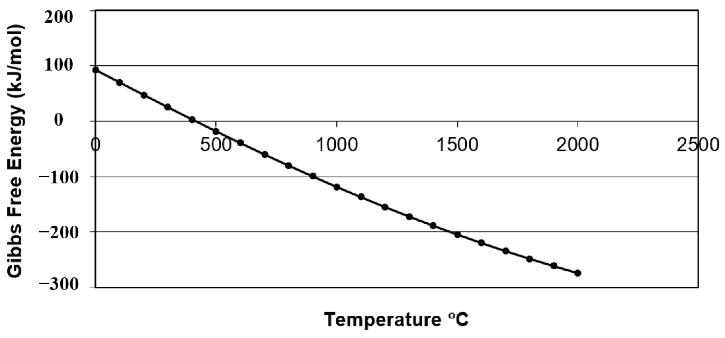
20]:
Figure 1 demonstrates the standard Gibbs free energy change (ΔG°) for this equation at various temperatures. The ΔG°, calculated using HSC Chemistry v10 software for the Gibbs free energy of formation for each compound involved in the reaction, becomes negative at 450 °C and above. This indicates that the reaction is spontaneous in the forward direction (from reactants to products in Equation (1)) and demonstrates the feasibility of synthesising AlN at temperatures above this value.
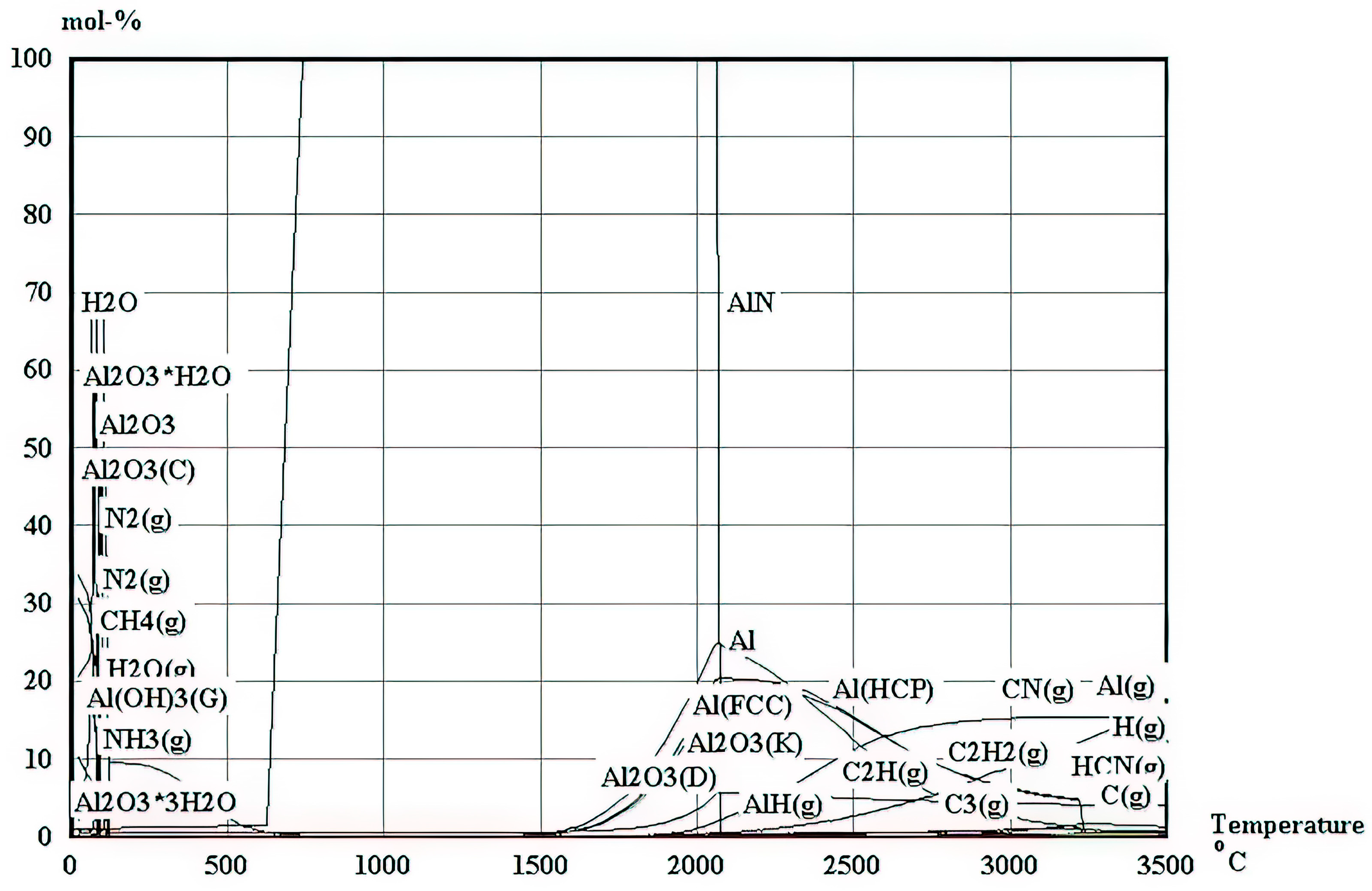
Also, for the elements in Equation (1), a full analysis of their thermodynamic speciation, conducted using HSC Chemistry v10 software and presented in
Figure 2, further reveals the possibility of the synthesis of AlN alongside some other oxides across a broad temperature spectrum ranging from 600 °C to 1700 °C. This temperature is ideal for the synthesis of AlN as it is in concurrence with the earlier suggestion that the synthesis of AlN is feasible at temperatures above 450 °C; it is also worth noting that above 1700 °C, AlN starts to decompose into aluminium metal and compound gases, while below 600 °C, many oxides and hydroxides are synthesised but into low concentrations of AlN. A further revelation from the thermodynamic analysis is the addition of carbon, which minimizes oxide formation. Consequently, in the preparation of the slurry, one mole of carbon was incorporated in conjunction with aluminium hydroxide and urea.
Consequently, the integration of chemical thermodynamics and a thermal analysis into the synthesis process forms the rationale behind the selection of precursors and specific reaction conditions. This approach enables the successful creation of AlN coatings, in line with the overall goals of improving the functional properties of the coated surfaces.
3. Analysis of Thermal Behaviour in Coating Procedure
A two-dimensional (2D) transient heat transfer model was developed to predict the temperature profile during the interaction of the laser with the coating and substrate. The analysis was carried out using commercial finite element analysis software, specifically FLUENT. The energy equation, fundamental to the heat transfer analysis, was formulated in relation to the enthalpy at the melting temperature, the cumulative heat loss resulting from convection and radiation, and the liquid fraction parameter (
β) [
21]. The energy balance in the heat transfer is represented by Equations (2)–(4), derived from Ref. [
21] and consistent with established thermal analysis in laser processing.
In this model,
T denotes the instantaneous temperature,
Tl stands for the liquidus temperature,
Ts represents the solidus temperature, and
T∞ represents the ambient temperature. The density of the material is given by
ρ, and
k indicates its thermal conductivity. Time is denoted by
t. The combined heat transfer coefficient is represented by
hc. In the model,
x and
y refer to the directional axes along the depth and the width of the domain, respectively. The velocity of the melt pool in the x-direction is expressed as
u, while
v represents the velocity in the y-direction. The directional vector in the plane is noted as
n (
x,
y). Lastly,
S″ is defined as the heat source term for the coating, which is defined as
where
I0 is the laser’s irradiance (alternatively referred to as its power density and expressed in units of power per unit area), and
δBL is the Beer–Lambert absorption depth.
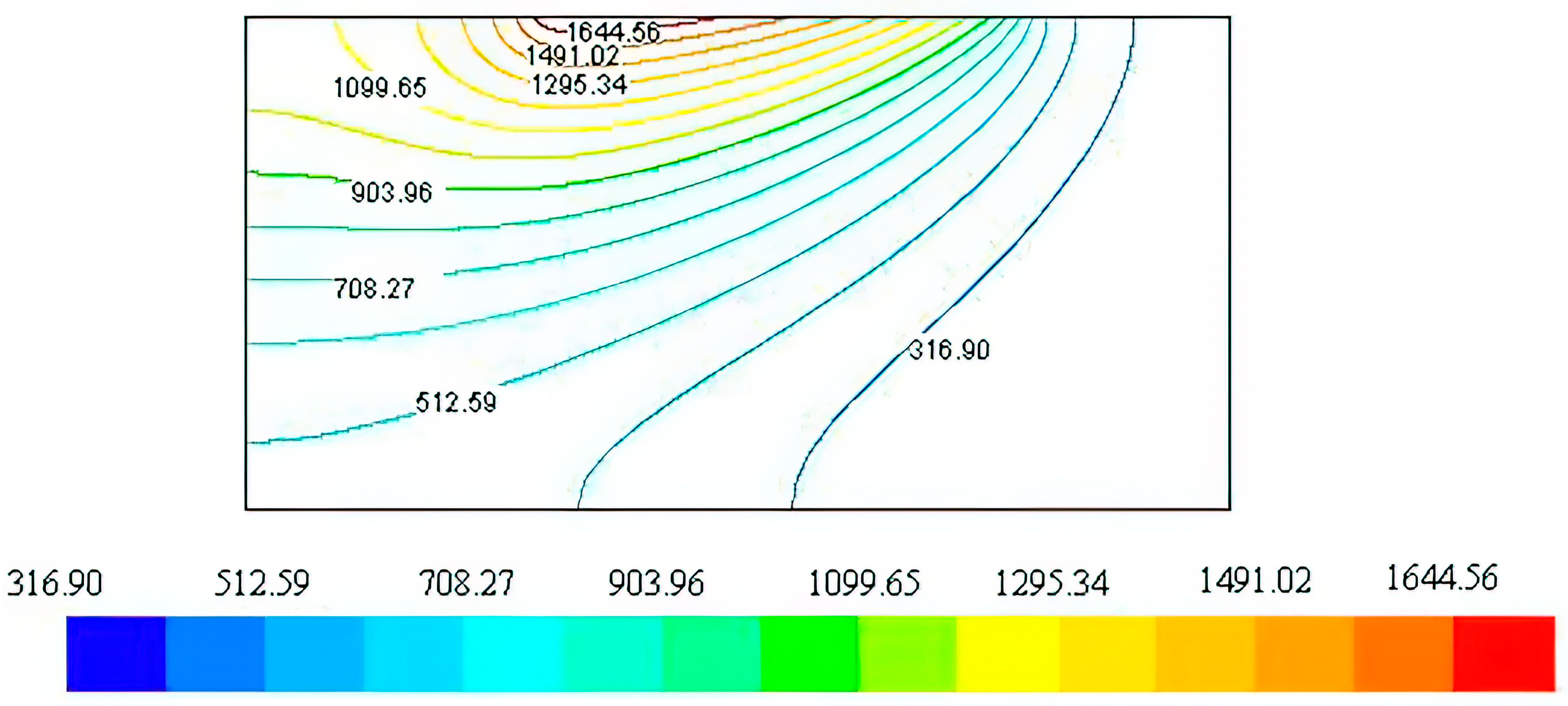
The simulation was conducted across a broad spectrum of power levels (400–800 W) and traverse speeds (1.0–1.5 mm/s). In accordance with the experimental procedure, a 2.5 mm square-shaped laser beam was utilised. The pattern illustrated in
Figure 3 is the temperature distribution result at a specific laser power of 650 W and a traverse speed of 1.25 mm/s. In this scenario, the peak temperature reaches approximately 1544 °C, which falls within the feasible range for the formation of AlN. This range is aligned with previous discussions [
22,
23] that underscore the importance of maintaining the synthesis temperature below 1700 °C to prevent decomposition while ensuring efficient AlN formation. This temperature range is also effective in achieving the adequate melting of the base material. This facilitates the formation of a metal matrix composite at the interface of the substrate and the coating which is enhanced by a range of temperatures that are sufficient to melt the substrate material.
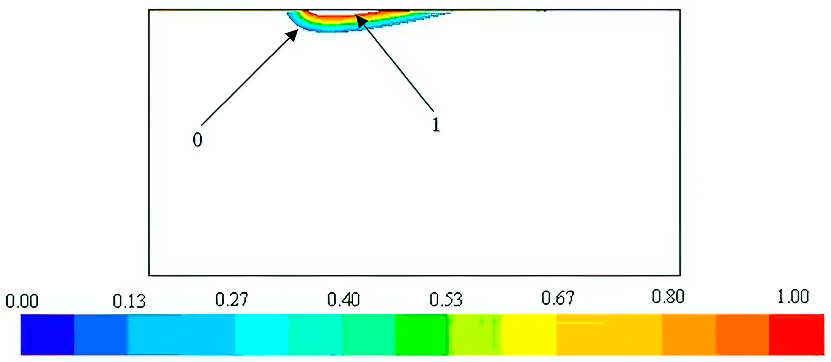
Figure 4 illustrates melt pool contours that suggest both the possibility of melting the steel substrate and the potential to create a metal matrix composite at the coating–substrate interface, which is in line with the heat transfer simulation’s predictions.
4. Experimental Methodology
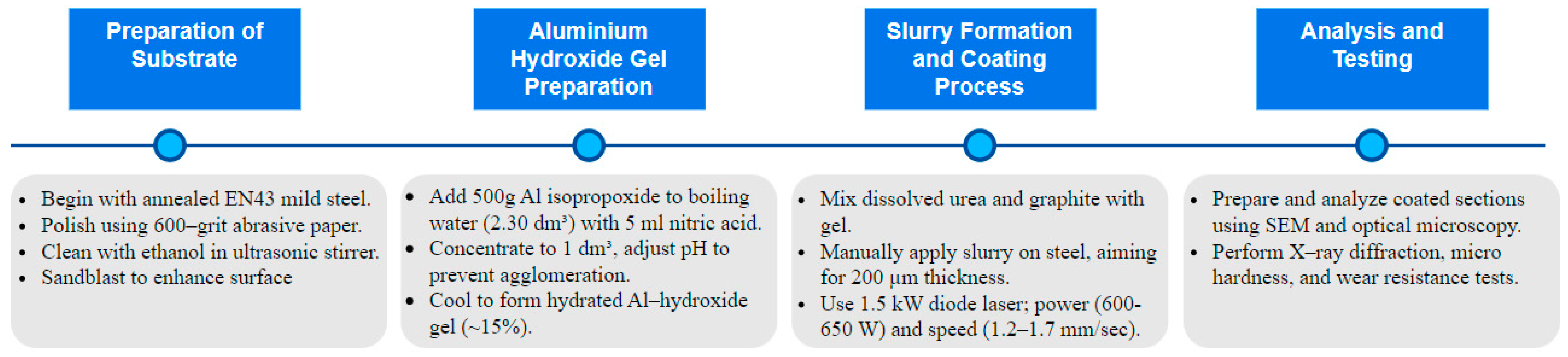
A comprehensive flowchart of the experimental methodology is presented in
Figure 5, illustrating the sequential processes from substrate preparation through to analysis and testing. The substrate used was standard annealed EN43 mild steel [
24] with dimensions of 50 mm × 50 mm × 5 mm which was obtained from metals4u.co.uk, and its detailed composition is provided in
Table 1. The specimens underwent a polishing process with 600-grain grit abrasive paper, followed by a thorough cleansing in an ultrasonic stirrer using ethanol for 6 min, ensuring the removal of any surface impurities. Subsequently, the samples were sandblasted to enhance the consistency and wettability of their surfaces.
In the preparation of aluminium hydroxide gel, 500 g of aluminium isopropoxide powder was gradually added into a boiling solution containing 2.30 dm3 of distilled water and 5 mL of concentrated nitric acid. The solution was concentrated by evaporating it to a volume of 1 dm3 while continuously stirring at a 150 °C temperature. To refine the solution, more concentrated nitric acid was added in parts measuring 15–20 mL. The incorporation of acid aimed to lower the pH to 4.5, thereby enhancing the zeta potential to −30 mV and distancing the Al(OH)3·nH2O colloid from the isoelectric point of 6.5. This modification in pH was intended to decrease the rate of particle agglomeration. Upon returning to room temperature, the mixture transformed into a colourless gel consisting mainly of approximately 15% hydrated aluminium hydroxide. Urea, dissolved in a small quantity of water, was then combined with graphite and added to the aluminium hydroxide gel, forming a slurry.
The test specimens were manually coated with the slurry using a K hand coater, a standard procedure known for its good repeatability in achieving uniform and continuous coatings [
25]. The process was carefully controlled to maintain a coating thickness of around 200 µm. The heat source utilised in the coating process was a 1.5 kW diode laser (i.e., a Laserline 160–1500 LDL) with a rectangular laser spot size of 2.5 mm × 3.5 mm, emitting a combination of wavelengths at 808 and 940 nm. The laser’s focal plane position (fpp) was aligned with the surfaces of the slurry coatings. Various speeds and power settings were evaluated to identify a range of viable operating parameters. The ideal power and speed settings were determined to be within the ranges of 600–650 W and 1.2–1.3 mm/s, respectively. These parameters were established by evaluating the uniformity and continuity of the coatings. The samples were exposed to laser irradiation in an oxygen-free environment with a continuous flow of nitrogen to avert the combustion of urea. Coated sample cross-sections were polished and placed on a conductive resin substrate for further analysis A subsequent analysis of the microstructures was performed using optical microscopy and an SEM. The study also included an X-ray diffraction analysis employing a Philips XPERT-1 device equipped with a cobalt X-ray tube. Furthermore, each coating underwent microhardness evaluations using an MTS-XP indenter. Optical microscopy was used to image the indentation marks produced via Vickers microhardness testing with a 50 g load. The procedure specified loading and unloading times of 15 s and 10 s, respectively, with a dwell time of 5 s at maximum force. The loading and unloading rates were set at 0.2 mN/s, and the Poisson ratio of the EN43 mild steel coatings was considered to be 0.29. Wear testing was conducted using a universal ball-on-disk tribometer to evaluate the wear resistance of the AlN coatings. The tribometer, model TRB-01 supplied by Tribology Systems Inc. (Coatesville, PA, USA), features a load range of 1–1000 N and a maximum rotational speed of 500 rpm and is capable of simulating a wide range of wear conditions. In this setup, a WC-6% Co ball with a diameter of 3 mm was used as the counter body and pressed under a force of 30 N on the AlN-coated EN43 mild steel sample rotating at a speed of 30 mm/s. This coated specimen was mounted on the tribometer’s rotating disk, allowing for the assessment of wear under controlled conditions. In order to identify the trend of roughness variations corresponding to different speeds and power, a Taylor Hobson SURTRONIC-3 instrument was utilised to measure the surface roughness of the coatings. The device was set to measure roughness using a cut-off length of 15 mm, with 10 measurements taken across the surface to ensure comprehensive coverage and accuracy.
5. Results
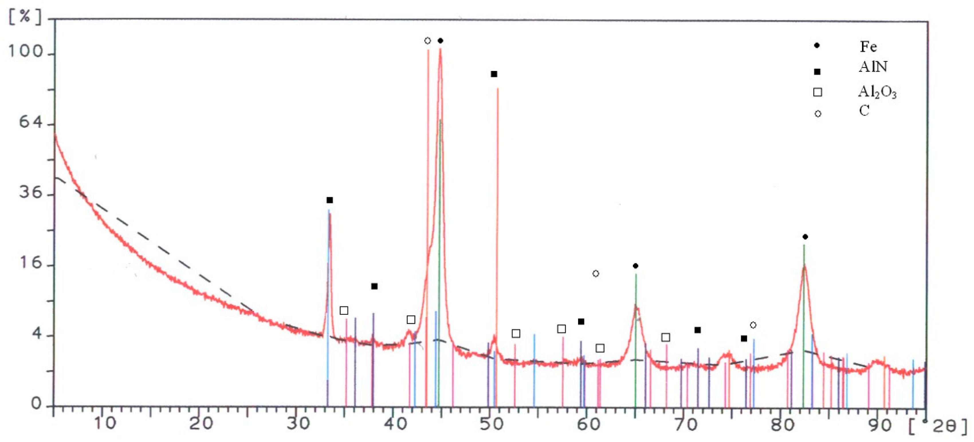
An X-ray diffraction spectrum identifying the phases in the coating is given in
Figure 6. The figure illustrates the dominant phase to be the AlN base, with some C, Al
2O
3, and, of course, the iron substrate.
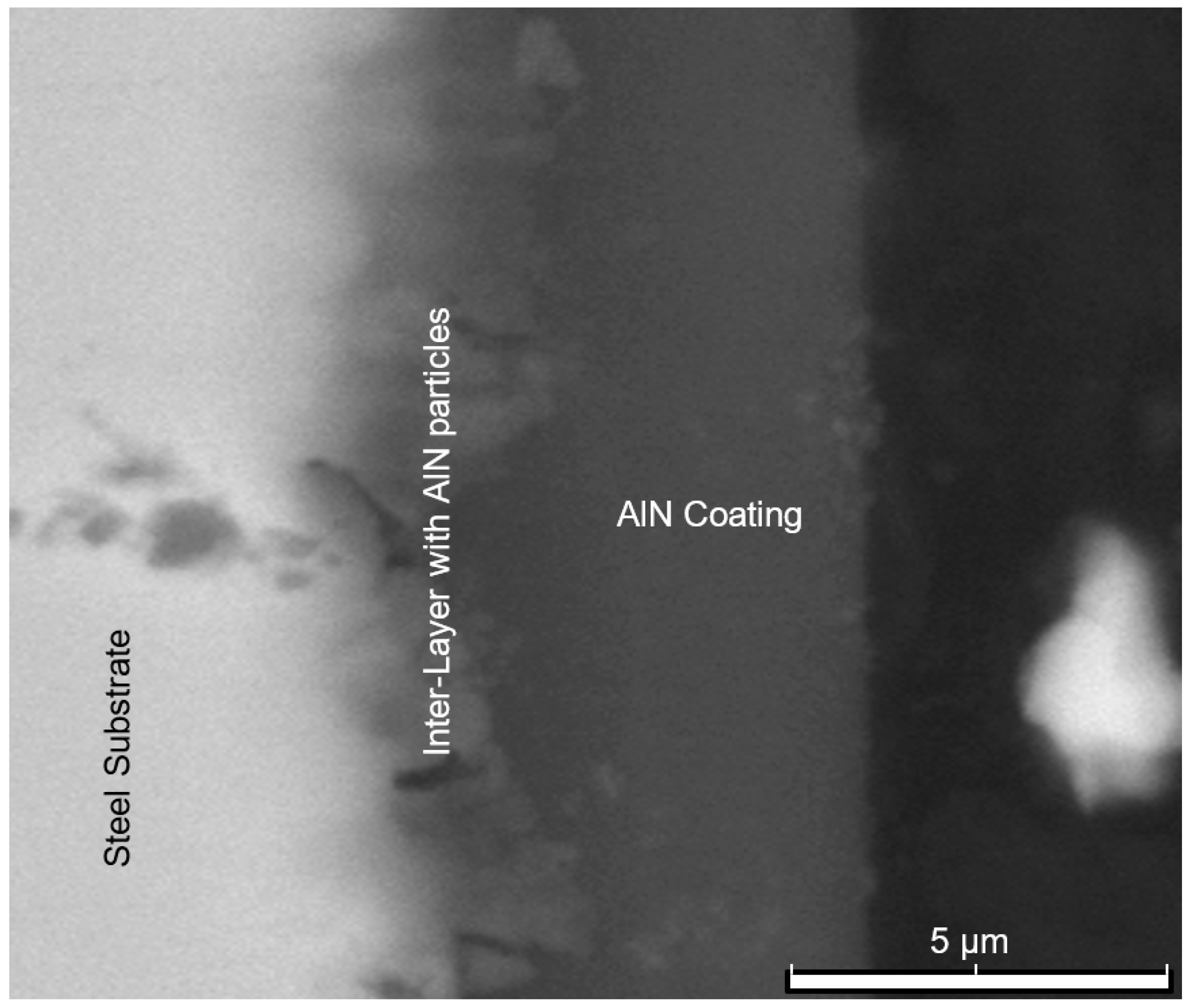
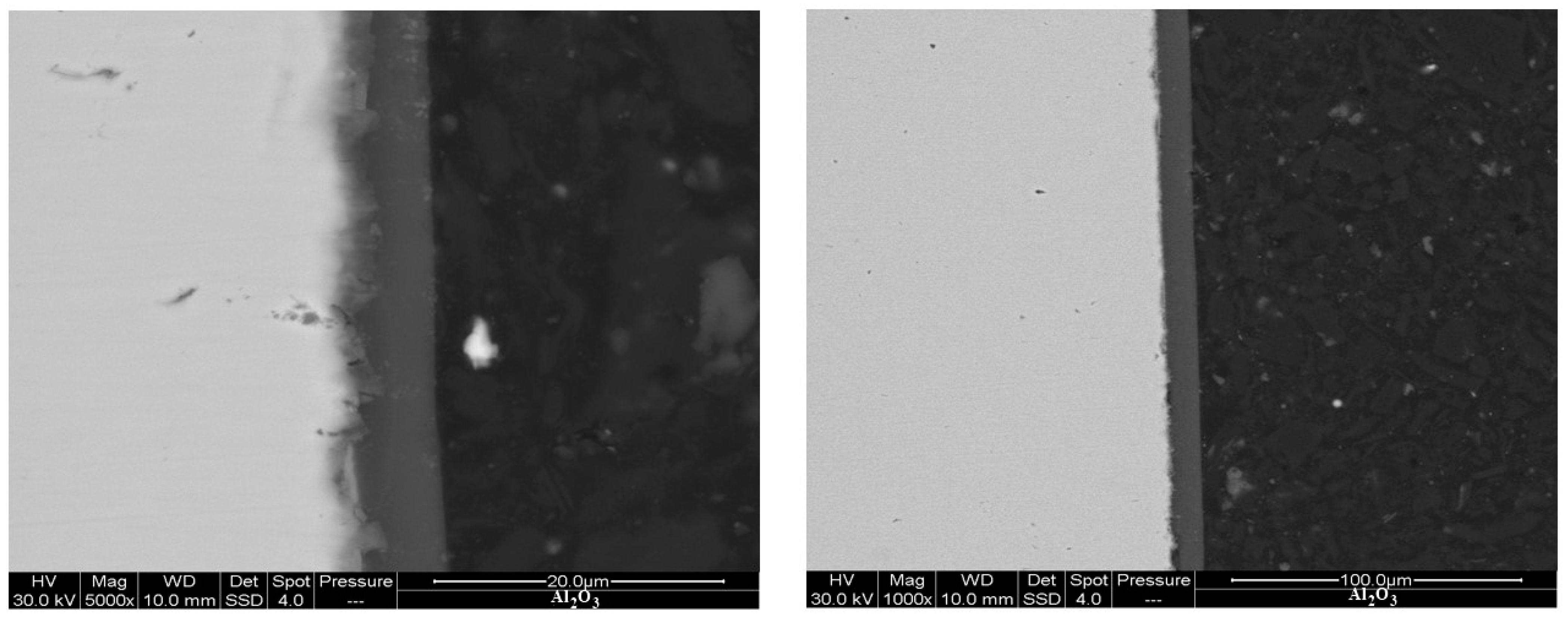
Figure 7 shows SEM backscattered images of the AlN coating, which exhibits a thickness ranging from 4 to 5 μm. Furthermore,
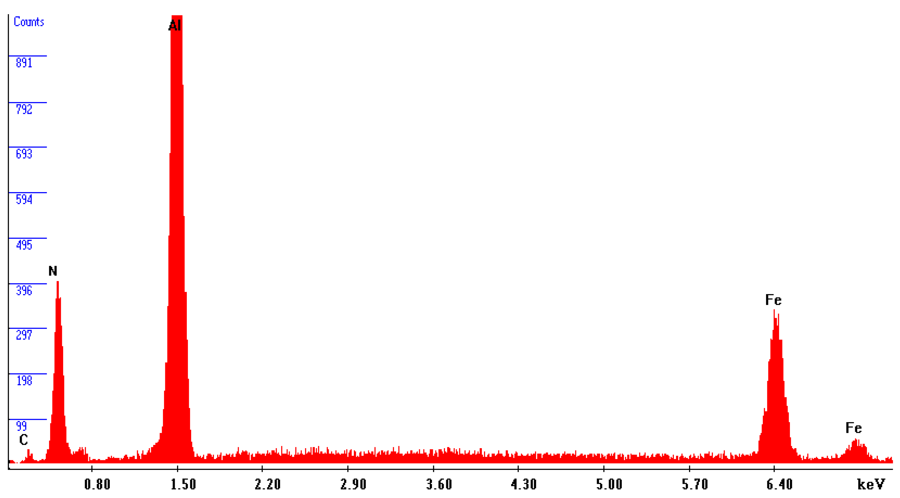
Figure 8 reveals the precipitation of AlN particles on the substrate’s surface, indicating the formation of an extensive interlayer between the substrate and the coating. The presence of this metal matrix composite interlayer serves as proof of a strong metallurgical bond and adhesion between the substrate and the coating. An elemental energy-dispersive X-ray (EDX) examination of the AlN particles seen in
Figure 8 revealed that the primary components are aluminium and nitrogen, as revealed in
Figure 9.
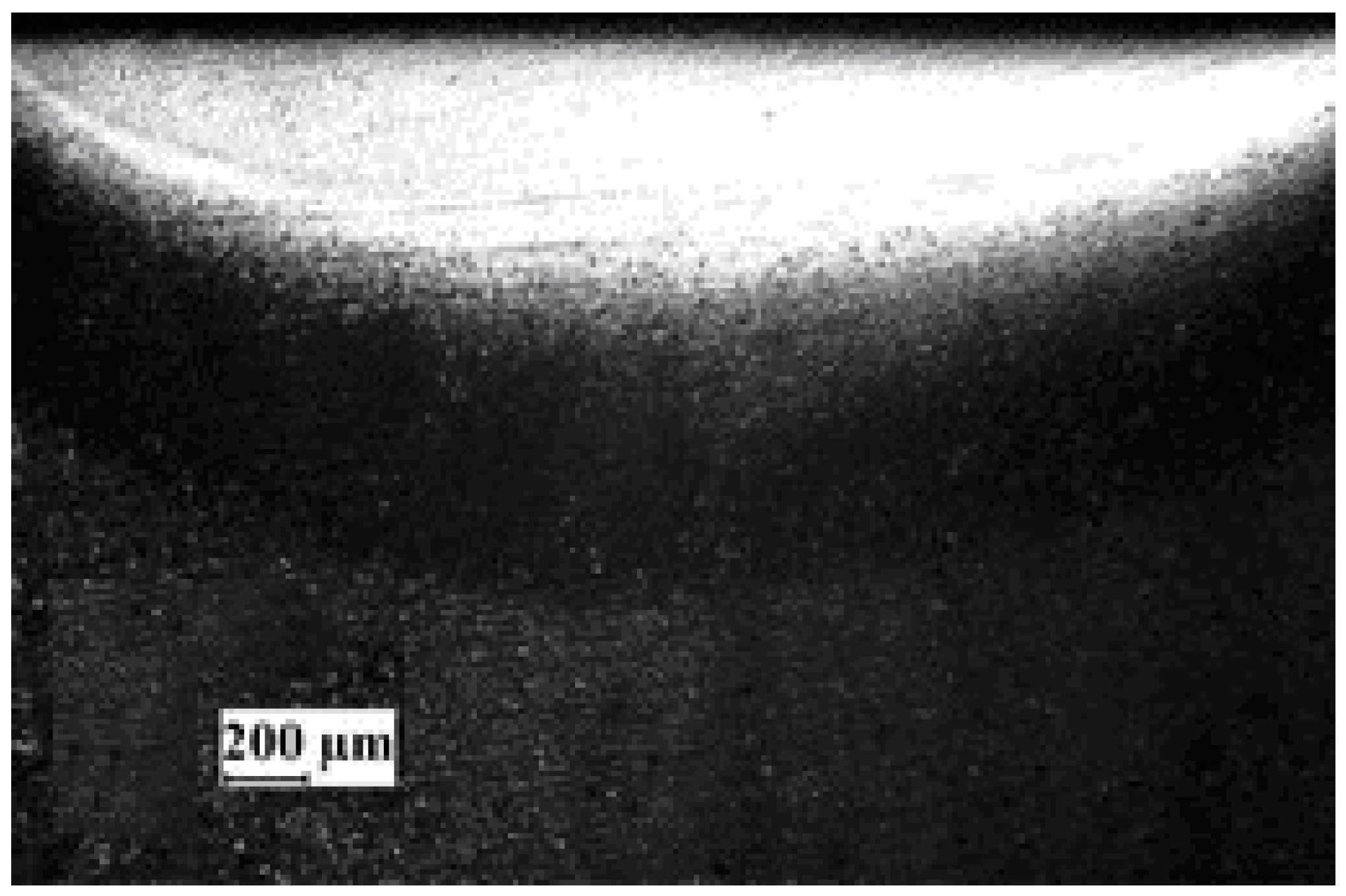
It should be emphasised that the thickness of coatings generated through the sol–gel method is greatly affected by variables like the concentration of the slurry, the sol viscosity, and the laser processing parameters used. Moreover, the sol wettability should be optimal. It is also crucial that the coating sol is spread uniformly to ensure the coatings are dense, consistent, and strongly adhered to the substrate. The thickness and uniformity of coatings synthesised via the sol–gel method are intricately affected by specific parameters, each playing a critical role in the final coating quality. The slurry concentration, typically ranging from 20% to 40% by weight, directly influences the deposition rate and ultimate thickness such that higher concentrations lead to denser and thicker coatings. Sol viscosity, measured in the range of 10–30 cP (centipoise), is crucial for ensuring a smooth flow and even spread on the substrate, preventing sagging or running. Laser processing parameters, such as laser power (450–850 W) and scanning speed (0.5–2.0 mm/s), are finely tuned to control the energy input, affecting the coating’s microstructure and phase composition. Furthermore, optimal sol wettability, characterised by a contact angle of 30° to 60°, ensures adequate adhesion and surface coverage, minimising defects like pinholes or cracks. This effect is only realised if, during the process, melting occurred at the interface, evidence of which is presented in
Figure 10, showing a typical melt zone produced during the coating process, indicating its typical dimensions to be 2.5 mm wide and 0.5 mm deep.
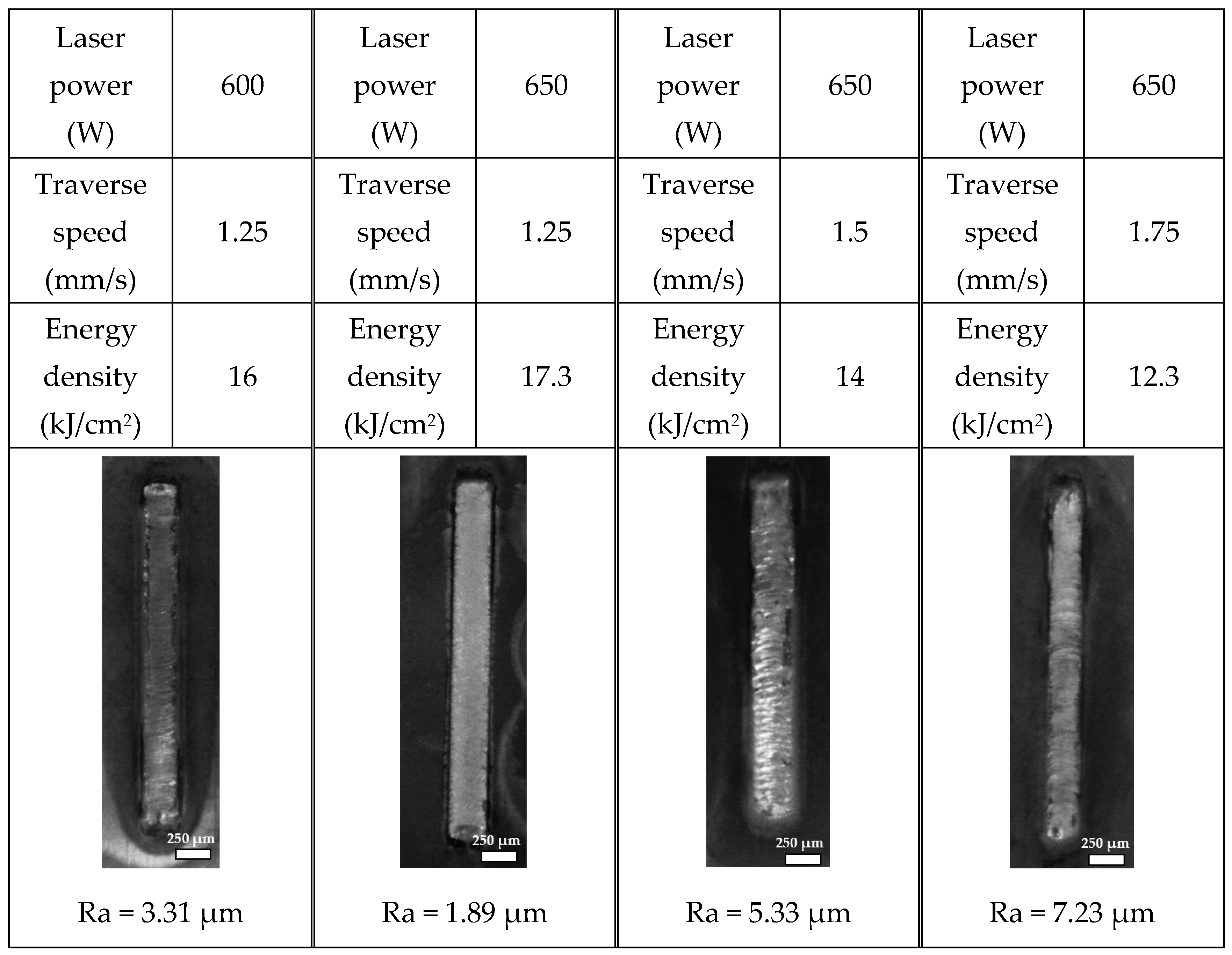
Figure 11 illustrates representative laser-processed tracks on samples coated with slurry, highlighting variations in power and speed within the specified operational value range. An increase in surface roughness was observed on the coated samples at higher laser scanning speeds. This phenomenon is partly due to the presence of unmelted particles remaining in the coating at these faster rates [
26]. For a more integrated analysis, laser power and traverse speed were combined into a single parameter termed energy density (E
d), calculated as the ratio of laser power to traverse speed, to provide insights into the energy per unit area delivered to the surface. The energy density (E
d) is defined as
where
v represents the traverse speed in millimetres per second (mm/s), and
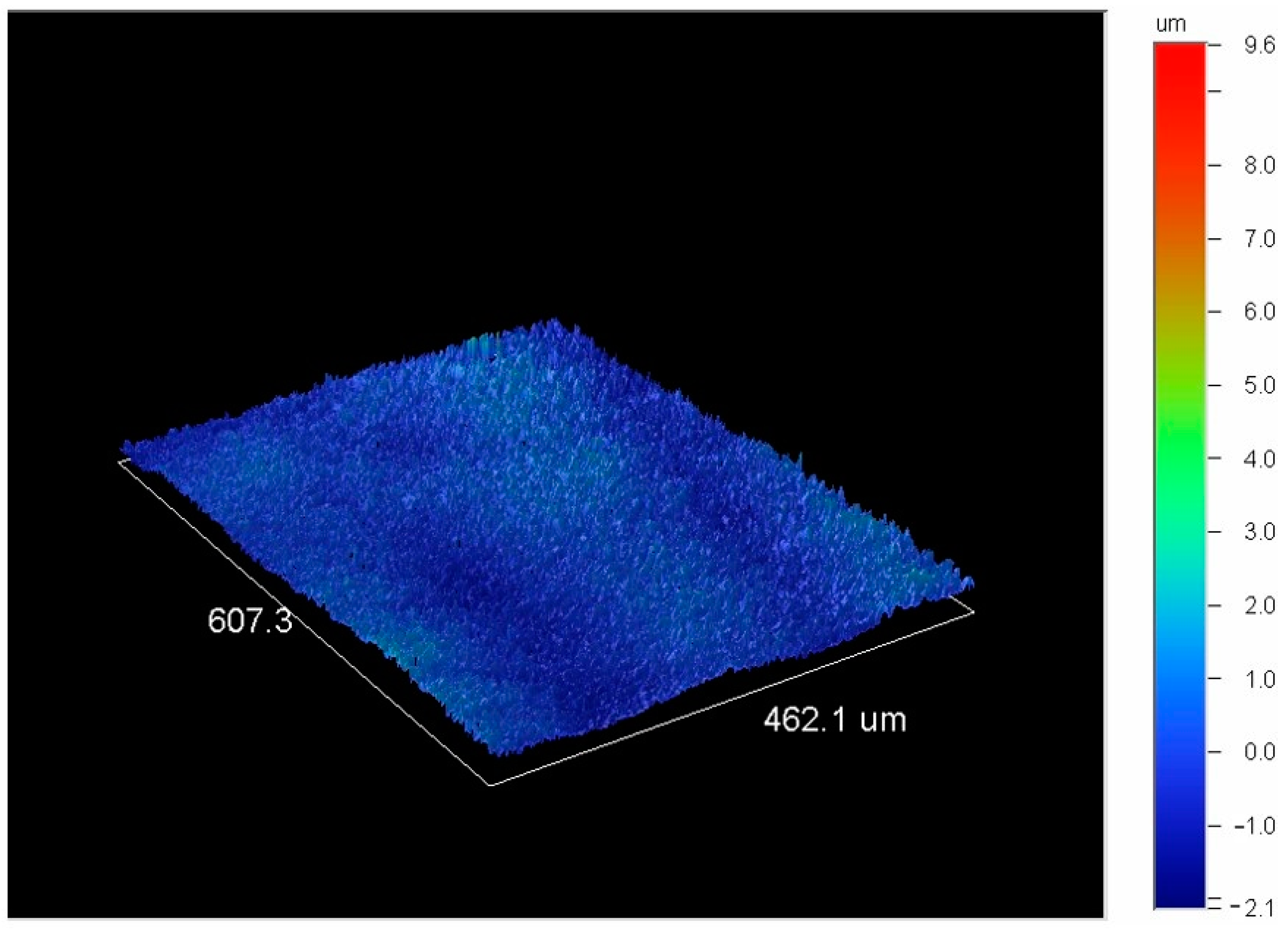
P is the laser power in watts (W). This metric enabled a comprehensive analysis of the process parameters’ impact on surface quality. It revealed that lower energy intensities lead to higher surface roughness due to insufficient particle melting, whereas an optimal energy intensity level corresponds to the lowest surface roughness, indicating the optimal balance of laser energy for achieving a smoother surface. Beyond this optimal point, an increase in energy intensity results in increased surface roughness, likely due to overheating and rapid solidification, contributing to a rougher texture. The finest surface finish, as evidenced by its three-dimensional surface topology captured with a Wyko white light interferometer (in
Figure 12), was achieved in the coating produced at 650 W of power and a speed of 1.25 mm/s.
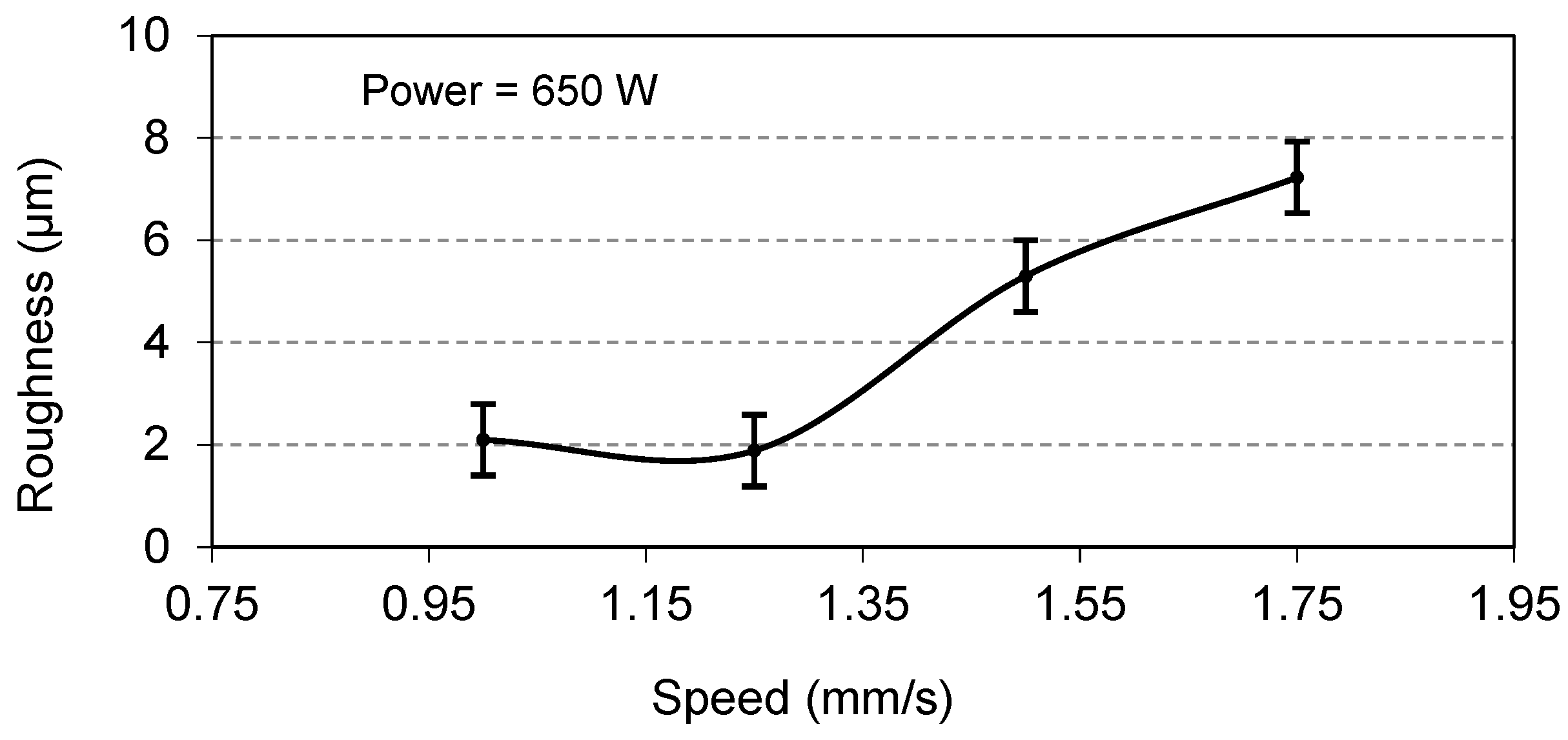
Coatings were prepared at a constant power of 650 W but at different speeds, and their surface roughness measurements are presented in
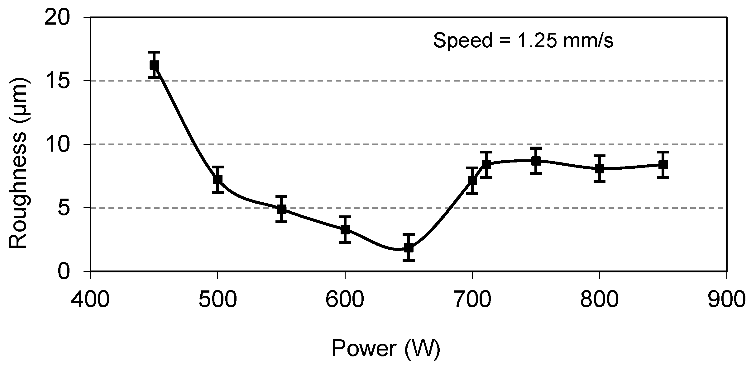
Figure 13. This graph indicates that an increase in speed initially reduces roughness to an optimal level, but a further speed increase causes a significant increase in roughness. This is because higher speeds provide insufficient energy for reaction formation, leading to more striations. Similarly, for the coatings prepared at a constant speed of 1.25 mm/s and varying power values, the roughness measured at the various power values is as plotted in
Figure 14. This figure shows an increase in power which results in a decrease in roughness up to an optimal power value beyond which any further increase in power causes an increase in roughness. It can be deduced from both
Figure 13 and
Figure 14 that the optimal surface roughness is reached at a traverse speed of 1.25 mm/s and a laser power of 650 W and is found to be in the range of 1.8–2.1 µm. It is also worth mentioning at this point that any abrupt increase or decrease in speed and power other than their optimal values will result in high surface roughness.
With regards to the hardness of the coating, the average composite Vickers microhardness for 20 indents with a load of 50 g was found to be in the order of 876 ± 5 HV, and the nanohardness was found to be in the order of 9.88 ± 0.20 GPa, values which are very near to previously reported results [
27,
28,
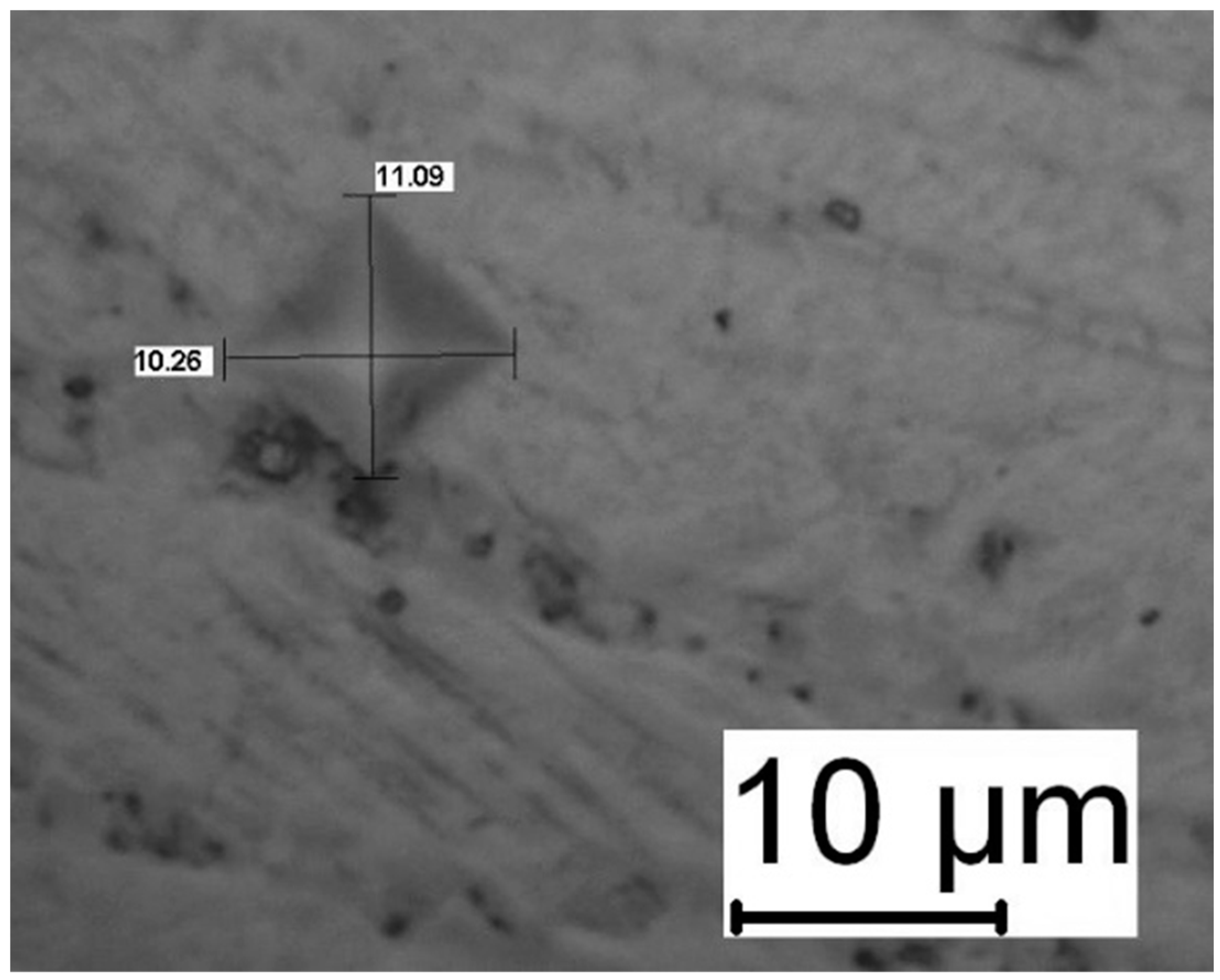
29]. As seen in
Figure 15, there were no microcracks at the hardness indentation edges, which is an indication of strong adhesion between the substrate and the coating.
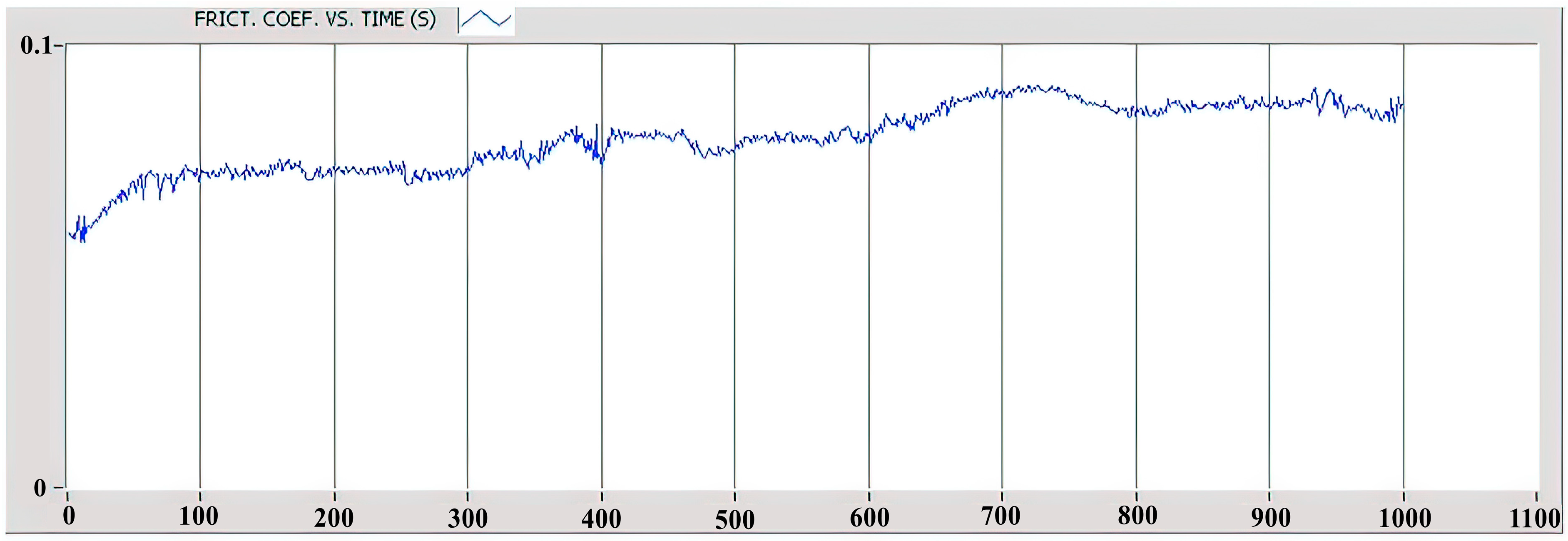
The wear rate of the AlN coating was determined based on the crater depth, the applied load, the radius of the circular crater, and the number of sample rotations. The results show that the wear rate of the AlN coating was approximately 1.6 × 10⁻¹⁵ m
3/Nm. Additionally, as illustrated in
Figure 16, the coefficient of friction was found to be less than 0.1 for the entire duration of the test, which lasted 1000 s according to the ASTM G99-17 standard [
30].
6. Discussions
The development of aluminium nitride (AlN) coatings using an integrated laser/sol–gel method marks a remarkable advance in the field of surface engineering. This technique facilitates the precise manipulation of the microstructure of the coating, thereby improving its mechanical and thermal properties. However, a comprehensive study of the limitations of the method side by side with its benefits is essential to provide a holistic understanding.
The integrated laser/sol–gel approach faces specific challenges. The most important limitation is that it relies on precisely calibrating laser parameters, including power density and scanning speed, which are important for achieving the desired coating properties. Variability in these parameters can result in non-uniform coating thickness and quality. In addition, the process requires an optimally formulated sol–gel precursor with controlled reactivity to prevent premature gelation or an insufficient reaction during laser exposure. On the other hand, scalability poses another major challenge. While the technique has proven effective at the laboratory scale, the transition to industrial-scale application requires extensive modifications to maintain coating uniformity and integrity on larger surfaces. The energy requirements and operating costs associated with high-power laser systems may also hinder the adoption of the method for commercial use.
Despite these challenges, the laser/sol–gel method exhibits distinct advantages over conventional techniques such as physical vapor deposition (PVD) and chemical vapor deposition (CVD). It enables the formation of dense, adherent coatings at reduced temperatures, mitigating thermal stress and potential substrate deformation, issues prevalent in high-temperature deposition processes. Moreover, this method accommodates the integration of intricate shapes and features within the coating process, offering a level of versatility seldom achievable with traditional methodologies. However, the intricacy of the laser/sol–gel process, necessitating controlled environments and precise laser parameter adjustments, stands as a disadvantage when compared to the straightforward nature of PVD or CVD techniques.
In summary, while the integrated laser/sol–gel methodology for synthesising AlN coatings exhibits certain limitations, such as procedural complexity and scalability concerns, its superiorities in terms of coating quality, material utilization efficiency, and adaptability to complex geometries render it a significant contribution to surface engineering. Subsequent investigations should focus on mitigating these limitations to facilitate broader industrial application.
7. Conclusions
The development of an AlN coating utilising the laser/sol–gel method has been successfully demonstrated, revealing its potential as a promising method for the application of AlN coatings on mild steel substrates. The presence of an AlN grain interlayer, which precipitates into the substrate material, ensures strong adhesion and bonding between the coating and the substrate.
The coating hardness is consistent with that of pure AlN coatings made by various commercial methods. Consequently, the aluminium nitride-based coatings developed in this study using the laser/sol–gel method demonstrate a superior surface finish, enhanced wear resistance, and a reduced coefficient of friction. Efforts are ongoing to further develop this technique, focusing on applying AlN coating to different substrates, covering larger areas, enhancing the coatings’ surface texture, and integrating additional elements into the coating. Efforts should also focus on refining the laser/sol–gel technique to enable its application on a wider range of substrate materials and sizes. Additionally, research should aim to enhance the microstructural and mechanical properties of the coatings. Exploring the integration of other elements into the AlN matrix could lead to coatings with properties tailored for specific applications, offering a significant advancement in materials engineering and surface technology.


