Article

Development of Cryogenic Systems for Astronomical Research

by
Yuri Balega
1,
Oleg Bolshakov
2,
Aleksandr Chernikov
2,3,
Aleksandra Gunbina
2,4,
Valerian Edelman
5,
Mariya Efimova
2,
Aleksandr Eliseev
2,
Artem Krasilnikov
1,2,
Igor Lapkin
2,
Ilya Lesnov
2,
Mariya Mansfeld
1,2,
Mariya Markina
4,5,
Evgenii Pevzner
2,
Sergey Shitov
4,6,
Andrey Smirnov
7,
Mickhail Tarasov
4,
Nickolay Tyatushkin
2,
Anton Vdovin
1,2 and
Vyacheslav Vdovin
1,2,7,*
1
Special Astrophysical Observatory RAS, Nizhnij Arkhyz 369167, Russia
2
A.V. Gaponov-Grekhov Institute of Applied Physics RAS, Nizhniy Novgorod 603600, Russia
3
Joint Institute for Nuclear Research, Moscow 141980, Russia
4
The Kotel’nikov Institute of Radio Engineering and Electronics of RAS, Moscow 101990, Russia
5
P.L. Kapitza Institute for Physical Problems RAS, Moscow 119334, Russia
6
Laboratory of Cryoelectronic Systems, The National University of Science and Technology MISIS, Moscow 119049, Russia
7
P.N. Lebedev Physical Institute of RAS, Moscow 119333, Russia
*
Author to whom correspondence should be addressed.
Photonics 2024, 11(3), 257; https://doi.org/10.3390/photonics11030257
Submission received: 24 November 2023 / Revised: 4 March 2024 / Accepted: 5 March 2024 / Published: 13 March 2024
(This article belongs to the Special Issue Optical Systems for Astronomy)

Abstract

:
The article presents a brief review of cooling systems that ensure various temperature levels (from 0.1 K to 230 K) for radio astronomical receivers of photonic and electronic (or optical and radio) devices. The features of various cooling levels and the requirements for the design of the cooling systems are considered in detail, as well as the approaches to designing interfaces for cooled receivers: vacuum, cryogenic, electrical, mechanical, optical, and other interfaces required for effective operation. The presented approaches to design are illustrated by a series of joint developments of the authors carried out over the past 45 years, including those produced over the past year.

1. Introduction

Cooling systems, including those operated at deep cryogenic temperatures (LHe and lower levels), are frequently utilized to increase the sensitivity of the photonic and electronic devices used in the astronomic research [1,2,3,4,5,6,7,8]. Such cryogenic systems are represented by a wide range of hardware, from very big cryosystems [9,10] to extremely miniature refrigerators [11]. High sensitivity and an extremely small intrinsic noise are the main requirements for astronomical receivers. Deep cryogenic cooling meets these requirements like nothing else. “Why do low temperatures gain the attention of researchers? The fact is that the area near the absolute zero turned out to be not so “dead” as they thought a century ago: all movement stops, everything freezes, period! On the contrary, low-temperature physics can compete easily with any other field of natural science in terms of the abundance of physical phenomena, which are observed when substances are cooled to the temperature of liquid helium and lower”. © [12].
Cooling systems are characterized by different temperature levels, which mainly determines their design. We should dwell on the very definition of the temperature and the scale on which we work. In this review, the Kelvin scale will be used in Dalton’s infinite round-trip interpretation.
An equally important issue in the design of a cooling system for astronomical receivers is the operating frequency range. Partly, it defines the level of the required cooling. All these issues are discussed in the corresponding sections of the paper.
Astronomy has traditionally presented the most ambitious challenges in the development of highly sensitive receiving equipment for both optical astronomy and radio astronomy and their intersection in the terahertz range. Now, the cryogenics community publishes many papers about the development of cryogenic hardware for astronomy in its journals (for example, Cryogenics [13]), and astronomical journals regularly describe cryogenic astronomical equipment in their instrument-related sections (for example, the Astronomical Journal [14]). The pioneer of application of cryogenics in astronomy was G.C. Messenger [15]. Meanwhile, the active use of refrigerators in radio astronomy began with the work of W. Gifford and H. McMagon in 1959 [16] based on the technologies presented by Guy K. White [17]. Further, in 1966, the fundamentals for the development of a cryosystem, including its application in astronomy, were described by R.F. Barron [18].
In approximately the same years, Stirling machines were used actively in optical astronomy [19]. The basic principles of cooling the optical and IR detectors were outlined in [5,7,8,11,12].
In this paper, we analyze the development of the related equipment and methods and review the basic principles of designing cryogenic cooling systems for photonic and electronic receiving devices for astronomy, illustrating the discussion by both our own developments and the best examples of modern astronomical cryogenic equipment used in many observatories around the world. World leadership in astronomical apparatus developments is gained on the frontier associated with space technologies. Space technologies are actively represented in two series of regular conferences [20,21] held by the IEEE community and the Space Cryogenic Workshop [12,22] held by the Cryogenic Society of America. It is here where the cutting edge of the research and development of cryogenic equipment for astronomy is formed, where the authors of this paper work, and where the results are reported.
The presented summative review has not only the academic interest, but also a significant practical value. The development of terahertz astronomy, which fills the gap between the optical and radio ranges, involves the addition of several dozen existing telescopes for creation of an extensive network of instruments in new territories of the Earth, where there are currently no terahertz instruments at all. A series of projects for the development of THz astronomy in northeastern Eurasia provides for the development of an extensive line of cryogenic receivers.

2. Classification of Cooling Systems for Astronomy

Cooling systems are used in a wide range of human activities, from fundamental physics research and advanced technology to medicine and cosmetology [23,24,25]. Each area forms its own approaches to the design of cryosystems and chooses independently the most effective approaches and technologies from their vast variety. The cooling of optical and radio receivers has formed a certain development culture on its own. In this line, astronomers need devices with the most ambitious and advanced specifications. At the same time, the types and features of the cryosystems manufactured for various astronomical telescopes have fundamental differences depending on an extensive set of factors, ranging from the band of the electromagnetic spectrum, in which the receiving device operates, to the atmospheric and climatic conditions at the observatory location and the design of the telescope, where the cooled receiving device operates.
Cryogenics as a science emerged over 100 years ago. The foundations of approaches to engineering of cryogenic systems were also laid many decades ago. Development engineers devised certain approaches to classification and methodology in the related fields and have accumulated extensive experience and knowledge about the properties of various materials for cryogenics. All this knowledge is summarized in extensive bibliography. However, there are certain cryogenic Bibles which each developer trusts and holds in his or her bookcase. In the English-language segment of the literature, such a Bible is the Brookhaven Reference Book [26], and in the Russian-language segment, it is the Malkov Reference Book [27]. After extensive discussions and disputes regarding which one is better, personal communication between the developers of cryosystems led eventually to the recognition that the books complement each other well and to the mutual exchange of available reference books. However, direct application of the available extensive knowledge and design approaches in specific fields and particular astronomy branches seems inconvenient. Not everything is equally suitable, and many things required, including new ones, simply do not exist. This publication is intended to systematize the current status of the developments in this area.

2.1. Frequency Range of Astronomical Instruments and Their Cooling Problems

Having started in the optical range of the electromagnetic wave spectrum due to the excellent photodetecting devices which each of us is endowed with, astronomy has acquired a multi-frequency character by now and is currently equipped with millions of eyes, i.e., detectors capable of operating at extreme sensitivity levels in the entire spectrum of electromagnetic radiation (EMR) (Figure 1), from ultra-low frequencies to the gamma ray part of the spectrum. In the areas at the spectrum edges, cryogenic cooling is not needed today in practice due to the perfection of semiconductor technologies in the low-frequency range and to the enormous energy of the X-ray and gamma quanta, which do not require cooling to be detected in the range of extremely high frequencies.
The EMR ranges, where the main scientific efforts of astronomers are focused today, cover two areas, specifically, the terahertz (THz) and the optical ranges, including the VUV (vacuum ultraviolet) band. These ranges require receivers with deep cryogenic cooling. This does not mean that there is no progress in the development of other ranges. It does exist and also requires cryogenic cooling sometimes. However, the scale of the need for cryogenics in that field is not comparable with the demand for photonic devices in optics or for electronic devices in the THz range. However, the THz range lies exactly between the traditional microwave radio electronics and the far-infrared optics combining the technologies and approaches inherent in both of them.
Therefore, the presentation below will focus on the problems of astronomy of these ranges.

2.2. Temperature Levels of Cooling for Astronomical Receivers

Astronomy uses a wide range of cooling from the boundary of cryotemperatures to extremely low sub-Kelvin levels. Table 1 shows the general classification of temperature levels of systems used.
The professional community divides the cryogenic temperatures into conventional levels. Cryogenic temperatures are the temperatures below 100 K (120 K in the USA). Non-cryogenic cooling is used quite widely in optical astronomy, as well as in climatic test chambers, in order to study the characteristics of devices and materials. The cryotemperature range is characterized by liquefaction and, for the most part, solidification of the majority of the gases present in the atmosphere. In particular, at T = 90 K, oxygen turns into liquid at atmospheric pressure. Nitrogen, which liquifies at 77 K, is extremely widely used in astronomy as both an independent and relatively cheap cryo-agent and an auxiliary agent for cooling radiation shields at deeper cooling. The main accepted temperature levels are given in Table 1.
The next characteristic level is the hydrogen level (~20 K). Here, not only the phase transition of the main hydrogen isotope occurs, but the Debye also temperature zone begins for the main structural materials, from which the components of cooled astronomical receivers are made. This leads to a dramatic change in their thermal characteristics (heat capacity, thermal conductivity, and thermal diffusivity). Despite certain fears caused by the explosive hazard of hydrogen mixed with atmospheric oxygen, liquid hydrogen is still used as a cryo-agent by the professional community. Also related to the hydrogen temperature level is a wide class of closed-cycle refrigerators, which have been and are used currently in astronomical applications, although more often as cryo-vacuum pumps of cryo-vacuum chambers for a wide variety of purposes, from vacuum deposition installations, where detectors for astronomy are manufactured, to testing chambers, where pre-launch studies of space equipment are carried out. However, hydrogen-level refrigerators are also used to cool astronomical receivers. It should be noted that they do not contain gaseous hydrogen, since the working gas is helium. Almost until the end of the 20th century, regenerators of cryorefrigerators, where heat exchange takes place due to gas expansion, were made of antimonial lead. The efficiency of such regenerators dropped dramatically in the vicinity of the hydrogen temperatures due to the transition of the material through the Debye temperature. When rare-earth regenerators began to be used instead of antimony–lead alloys, the problem was resolved, and the operating temperature of such refrigerators dropped to the helium level (4 K and lower, to the limit of 2 K). As is known, when the pressure decreases from the atmospheric level to vacuum, the temperature of the main helium isotope 4He can reach 1.6 K. This is the helium temperature level.
Lower temperatures (at the sub-Kelvin levels, i.e., below 1 K) require different approaches to cooling, including the use of the 3He isotope, thermomagnetic cycles, laser-based and other cryocooling technologies. Note that these temperatures are extremely actively used by astronomers for deep cooling of superconducting detectors in the terahertz range.
Even lower temperatures currently achieved by physicists are frequently used for other purposes, primarily the study of the extreme conditions not found in nature, such as Bose–Einstein condensate. Such a setup, operated at a temperature of about 10 nano-Kelvin [28], is installed in a laboratory adjacent to the laboratory of the authors of this paper. The application of the results of these studies in astronomy also has great prospects. On this basis, it is possible to construct highly stable time and frequency standards necessary for precision radio astronomical observations in the VLBI (very large baseline interferometer) mode. However, this is a distant prospect. Today, physicists have already passed the nano-Kelvin milestone. Among the many practical temperature scales in use [29,30,31] for astronomical instrumentation, the Kelvin–Dalton logarithmic scale, which is infinite towards absolute zero, is applied. The levels of the cryogenic temperatures listed in Section 2.1 will be further illustrated by examples of the development of the corresponding astronomical instruments. However, when we speaking about temperature of cryogenically cooled receivers, we should remember that the temperature of different components of the receiver is not the same and any thermometer measures only its own temperature.
The second fact upsets experimenters even more: although temperature is a measure of kinetic energy by definition, it must be measured in the equilibrium state. Since cryogenic receivers, as a rule, are not in the equilibrium state, their temperature in the strict sense is uncertain; this creates an extensive range of interesting scientific and engineering problems in the context of the radiophysical and optical properties of the receiving systems, which are discussed below, for the receiver elements that are not in the equilibrium state.

2.3. Main Types of Cryosystems for Astronomy

Cryosystems used to cool astronomical radiation receivers can be divided into the following groups: cryo-accumulators, cryorefrigerators, and their variations, as well as their combinations. Along with the cooling systems based on the use of gases and gas machines, various types of gas-free cooling systems are known, in particular, first of all, thermoelectric and thermomagnetic ones. In recent years, laser cooling systems have also appeared, though they have not yet found application in astronomical research. One of the obvious and very popular applications of the devices with deep (nano-Kelvin) laser gas cooling in the Bose–Einstein condensate state opens up enormous prospects in increasing the stability of time and frequency standards actively used to synchronize astronomical receivers operating in the regime of a VLBI.

2.3.1. Dewars or Cryo-Accumulators and Liquid Nitrogen Cooling Solutions

Cryo-accumulators use a pre-cooled cryo-agent in various phase states:
  • gaseous agent (a cold flow of N2, H2 and He gases);
  • solid agent (carbon dioxide); and
  • liquefied gas (nitrogen < 77 K, hydrogen < 20 K, helium < 4 K).
For millimeter- and submillimeter-range (or subTHz) receivers, liquid nitrogen or helium is used most often (depending on the requirements). Receivers in cryo-accumulators are placed in either a boiling liquefied gas or a so-called “vacuum basement”, i.e., the cavity between the outer and inner walls of the Dewar vessel. As a variant of the cryo-battery circuit, there is a flow circuit containing a separate Dewar transport vessel, as well as a closed or open line for supplying the cryo-agent to the cooling facility. The scheme of the cryo-accumulator with a “vacuum basement” is similar to the cryorefrigerator scheme, where a cryopanel with cooled receiver elements is attached to the cold stage of the refrigerator cooler. In essence, the energy required to maintain the temperature of the cooled object (elements of the receiving path of the astronomical receiver) below the state of thermodynamic equilibrium with the environment is stored in the form of a liquefied cooled gas and is easily estimated as the volume of the stored cryo-agent multiplied by the sum of its specific vapor formation temperatures and heat capacity at a temperature drop (see Formula (1)):
E = m (λδƬ + C),
where E is the energy or heat flow, which can prevent the supply of cold in a liquefied state, m is the cryo-agent mass, λ is the specific integral heat capacity of the cryo-agent, δƬ is the temperature difference used for cooling, and C is the specific heat of the phase transition.
The design of nitrogen Dewars (for example, Figure 2a shows a photo of the developed and manufactured nitrogen-filled cryostat) is quite simple, and design optimization is not difficult, whereas helium-filled Dewars require a more thorough thermal design. As a rule, they need nitrogen radiation shields to prevent radiation thermal inflows. To that end, in addition to the helium tank, the design provides a nitrogen tank with its own filling system. Estimates of heat flows are presented in Section 4.3.2. However, there is also the experience of creating nitrogen-free (Figure 2b) helium Dewars for astronomy, where radiation shields are cooled by evaporating helium of the appropriate temperatures.
The choice of the working gas and the volume of the Dewar is determined by the heat flows and the release of the cooled receiver itself. The analysis of the parameters of such systems, which are typical for astronomy, is given in Section 4.3.2.
Along with relatively simple liquid-nitrogen Dewars, many equally simple, efficient, and energy-saving closed-cycle refrigerators have been used in astronomy, mainly the Stirling machine. To reduce vibration loads, which are the main disadvantage of refrigerators as compared to Dewars, the split-Stirling version or other thermodynamic cycles were used more often, until the Cryotiger became a certain perfection of such machines. Comparable runs of cooling systems for various photodetectors using Cryotiger closed-cycle refrigerators were produced in various configurations for equipping optical telescopes [2,32,33] (Figure 3).

2.3.2. Hydrogen Level Refrigerators for Astronomy and Telecommunications

The hydrogen level of cooling has been and is used now actively in astronomy and radio telecommunications. Various types of cm and mm radio frequency detectors and amplifiers can be cooled by such coolers, which are relatively cheap, compact, and economical compared to the helium coolers.
The success in using low-noise HEMT (high electron mobility transistor) amplifiers produced by Saturn Research Institute (A.M. Pilipenko) in astronomical satellites at SAO RAS (Special Astrophysical Observatory of the Russian Academy of Science) gave rise to their further extensive use with other antennas: RT-22 (Simeiz), RT-13 (Metsahovi), and RT-64 at Bear Lakes and Kalyazin. In particular, a unique set of equipment for astronomy and telecommunications was created on the basis of these HEMT amplifiers.
One should also mention the extremely efficient system of cooling at the hydrogen level, which was developed by the authors of this publication and is used for the X-band antennas at Bear Lakes and Kalyazin, both for astronomical observations and for deep space communications. It worked successfully and is working currently as a component of the Spektr-R and ExoMars missions [34]. A photo of the cryogenic system is shown in Figure 4.
The key parameters that characterize the quality and, as a result, efficiency of such a receiver is the ratio of noise temperatures. If the receiver without cryogenics produces about 40 K of the noise at the input, and the antenna noise is 14 K, it is obvious that the atmosphere is not dominant, but makes a significant contribution. Cooling to a temperature of 6 K results in a decrease in the receiver noise to 5 K, and the system noise with the contribution of the atmosphere rises up to 19 K. This leads to a reduction in noise by almost three times and a similar increase in sensitivity. Strictly speaking, the system is closer to the helium level in terms of the temperature than to the level of liquid hydrogen, but it still does not belong to the class of helium refrigerators. The gain and the operating range of such a receiver are 30 dB and 8.4–8.5 GHz, respectively.

2.3.3. Cooling Systems of the Helium Level

Helium-level systems are actively used for cooling various coherent detectors (mixers), from Schottky barrier diodes (DBS) to mixers based on superconducting junctions. This approach has been presented both in classic papers, like [35,36,37], and in modern papers about receivers [38].
One of the most striking examples of an observatory, where detectors are cooled to the helium level, is SOFIA, a stratospheric aircraft-borne observatory [39]. The detecting devices are maintained at a temperature of 1.7–1.9 K.
However, it should be recognized that in recent years, with the transition to pulse tubes and rare-earth regenerators, helium-level refrigerators have been used more frequently.
Until recently, very little attention has been paid to the potential of deep cooling of the receivers to the helium level, which is one of the main types of the cryogenic systems used in optical telescopes. The reason was mentioned above. Specifically, it is that the BTA (Big Telescope Alt-Azimuthal) optical telescope operating in the optical and IR ranges does not need such systems, and on the RATAN-600 radio telescope, there is no need for cooling below the level of liquid hydrogen, since it operates at relatively long wavelengths in the conditions of a fairly significant atmospheric background. At the same time, the helium level was actively used in both the liquid and dry configurations of the refrigerator when developing the SAO receiver for RT-22 after the transition from the mixer to the DBS to the mixer at the superconducting junctions.
Currently, SAO RAS is preparing to switch to helium-level technologies for cooling the subTHz receivers on the BTA telescope. Moreover, the temperature of 4 K will be used only as a system of precooling for refrigerators of a deeper cooling level, which are presented in the next section. The cryogenic systems that are used in SAO RAS are described in more details in [40].
At the beginning of the cryogenic cooling era, cryo-accumulators and Dewars were mainly used in astronomy. However, the convenience of using refrigerators that do not require liquid gases has made them most popular in observatories. The ideology of unified cartridges with closed-loop 4 K refrigerators (Figure 5) should be recognized as a semi-industrial masterpiece of the approach to the design of cryosystems of astronomical receivers. It is implemented at the ALMA Observatory in an array of 64 telescopes, each of which is equipped with a set of cooled receivers of various frequencies of the THz range and replicated in hundreds of copies [41].
Cryogenic refrigerators, or gas fridge machines, operate by throttling or expanding the working gas in a cooler based on various thermodynamic cycles: Joule–Thomson, Stirling, Gifford–McMahon, etc., originating from the Carnot cycle and ultimately described by the equation of the state of the ideal gas (2):
PV = νRT,
where V is the volume, P is the pressure, ν = m/M is the amount of substance in moles, R is the gas constant, and T is the thermodynamic temperature.
Refrigerators of this kind are actively used to cool astronomical receivers down to the nitrogen, hydrogen, and helium temperature levels. Here, the energy of maintaining the temperature of the cooled object below the temperature of the thermodynamic equilibrium with the environment is received from an electrical power source. At the same time, energy has a very significant value. The fact is that following the basics of thermodynamics, the efficiency of the cycle drops sharply. Whereas nitrogen-level refrigerators having a cooling capacity of several watts consume only hundreds of watts, L-helium-level refrigerators with a cooling capacity of 1–2 watts require a compressor power of 4–7 kW. However, it should be recognized that the given values of nitrogen refrigerators relate to the Stirling cycle, which is essentially close to the ideal reverse Carnot cycle. Helium refrigerators employ other cycles and, in particular, the presented values relate to Gifford–McMahon machines (Figure 6) and the coolers based on pulse tubes.
There are two main methods of cooling detectors to a temperature below 0.3 K, specifically by using adiabatic demagnetization refrigerators or refrigerators based on dissolution of 3He in 4He. At the turn of and just below 0.3 K, sorption refrigerators also work on 3He and 4He.

2.3.4. Cryosorption Cryostats

Cryosorption devices are actively used in astronomy (for example, in [42]), when it is necessary to achieve sub-Kelvin (subK) temperatures. One of the first mentions of the development of a 0.3 K system for mounting a subTHz receiver on the BTA optical telescope is given in [43], and the system development was only at the design stage then. In that article, a cryogenic system was proposed that provided the operating temperature T~0.3 K of the receiving antenna arrays. This is a closed-cycle system; i.e., it does not require liquid refrigerants (nitrogen and helium). It is based on a refrigerator on pulse tubes and two sorption pumps on 3He and 4He. Despite the lack of funding for this project at that time, the development of this cryogenic system was continued, and the next stage of development was already presented in [44]. The photos of the elements of the 0.3 K cooling system are shown in Figure 7.

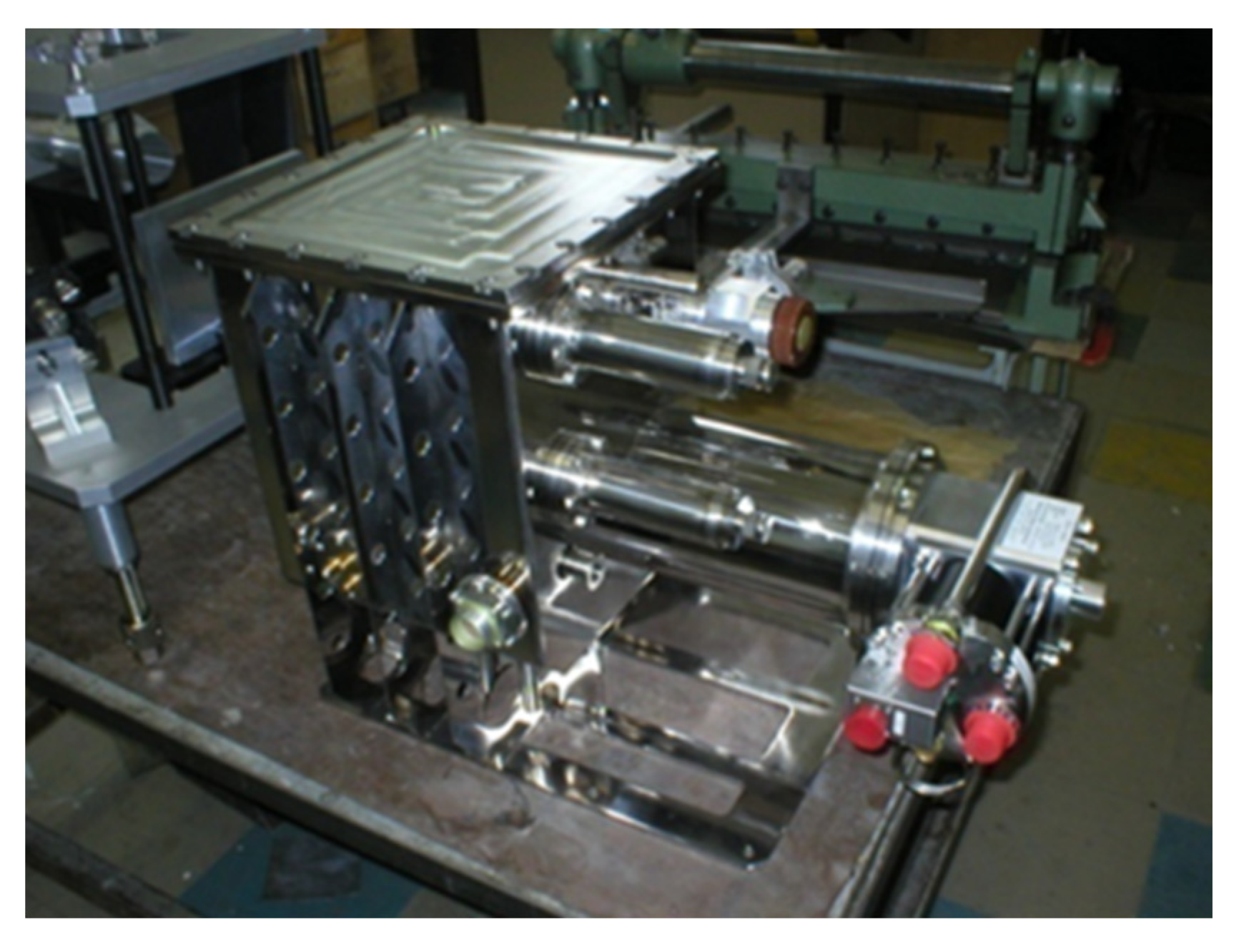
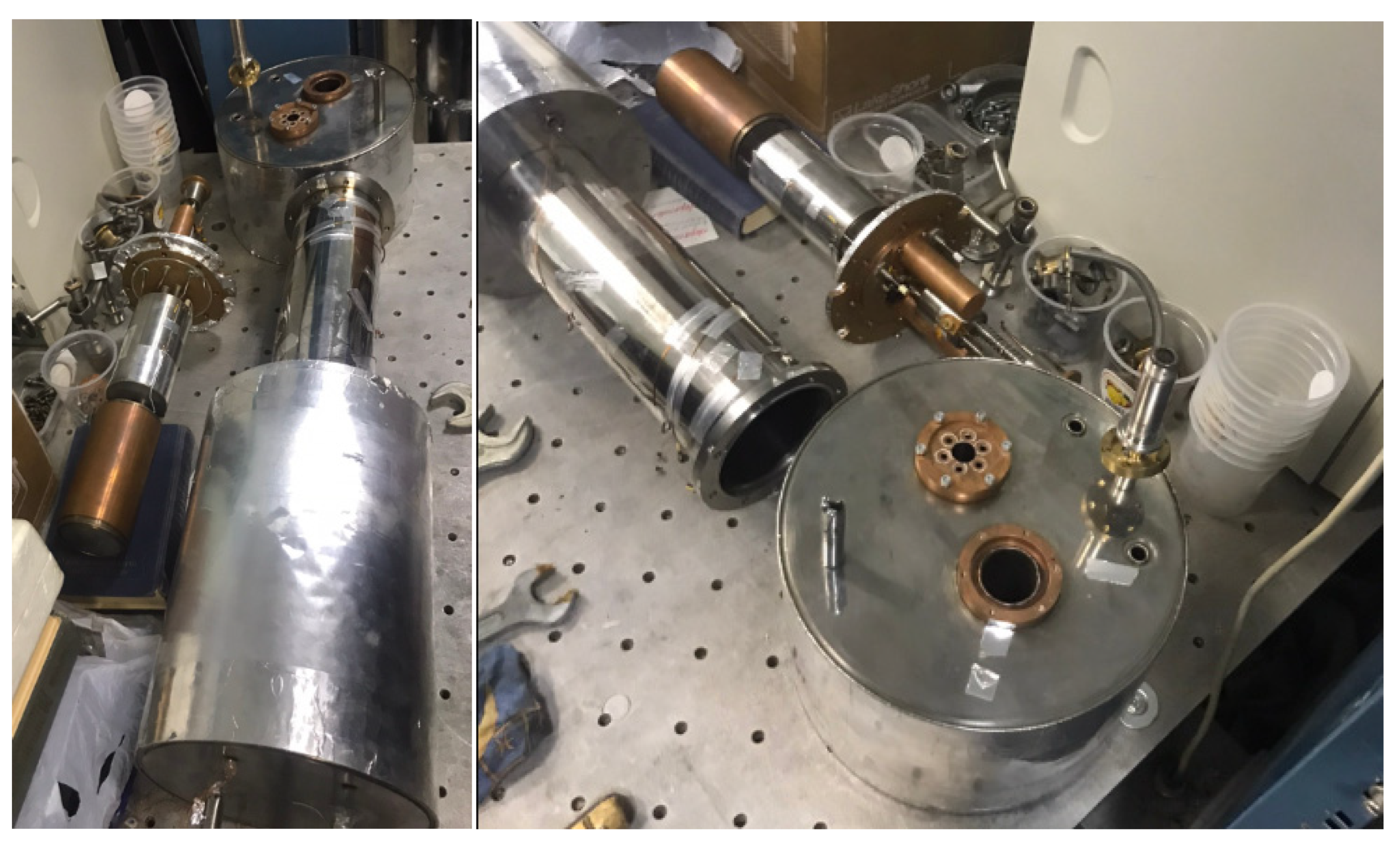
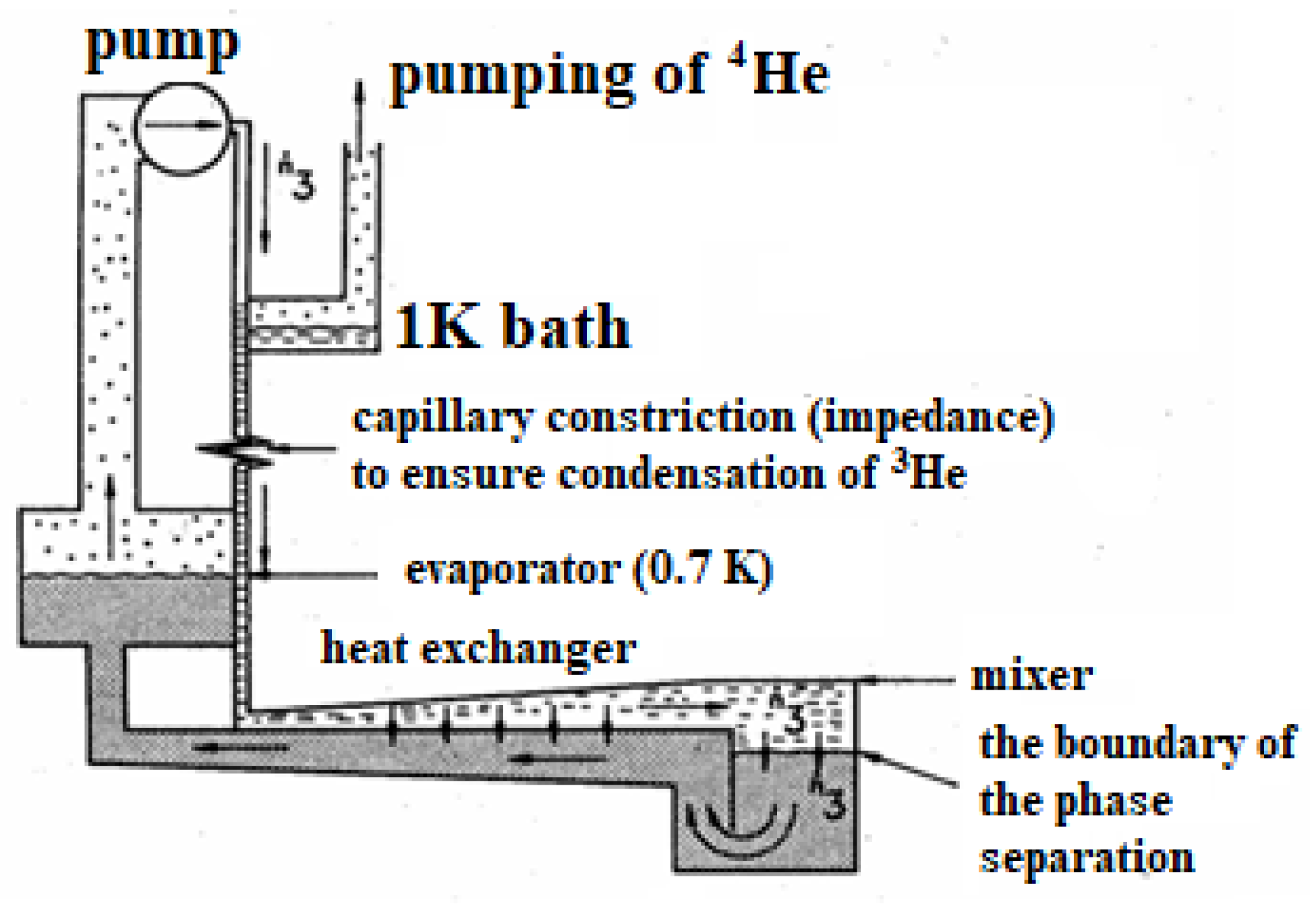
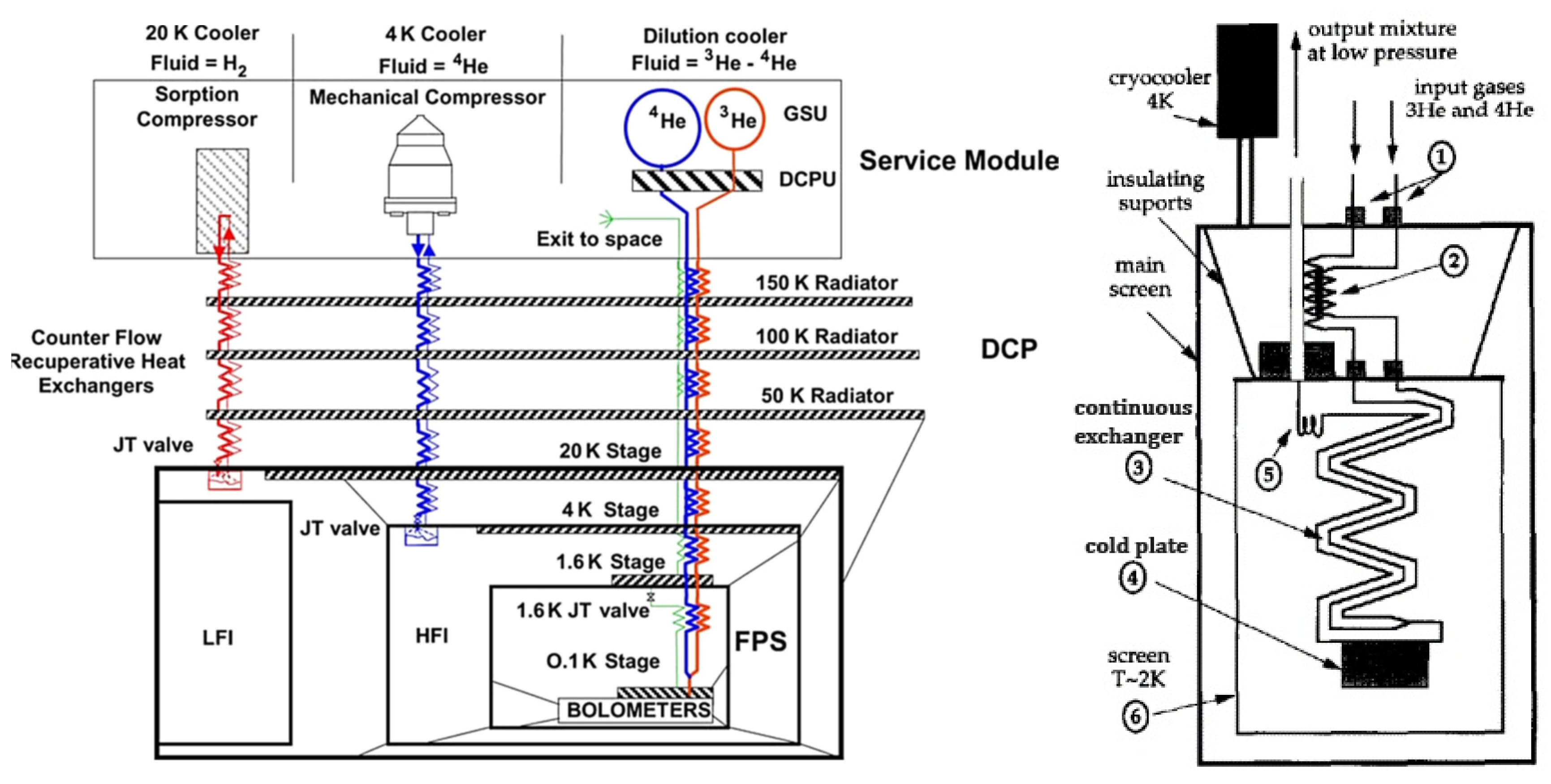
2.3.5. Dilution Cryostats

An even lower cooling level (0.1 K and below) required for radio astronomy can be provided by dilution cryostats. A mixture of two isotopes of helium 3He and 4He at a temperature below 0.8 K decays spontaneously into two phases, depleted and enriched 3He, which ensures cooling in the dilution cryostat to transfer the 3He atom from the enriched phase to the depleted one, it is necessary to spend energy (absorption of the heat of the dissolution process). If the 3He atom crosses the phase interface continuously, the mixture will be effectively cooled. Thus, the principle of operation of the dilution cryostat is based on the circulation of 3He and its transfer from one phase of the mixture to another.
Compared to the adiabatic demagnetization systems, the advantage of this system is that it is a continuously operating device and does not require the use of magnetic salts or an external source of a powerful magnetic field, which can negatively affect other components of the experiment (for example, detectors). In addition, its mass is very small at the coldest stages, and the cooling power can be distributed over a large focal plane, which avoids the narrow joints and heavy supports required by adiabatic systems. It is also possible to cool mechanical supports and electrical wires (by removing the heat that is transferred from higher temperatures through a reverse flow heat exchanger) without reducing the minimum temperature (for an example, see [45]).
The schematic diagram of operation of the classical dilution cryostat [46] is shown in Figure 8. The performance of the dissolution cycle (W/(mol/s)) is determined by the formula
d Q d t = ( 94.5 T 2 12.5 T c 2 ) d n d t ,
where Q is the power supplied to the dissolution chamber (mixer); T and Tc are the temperatures of the mixer and concentrated 3He at the entrance to the mixer, respectively; dn/dt is the circulation rate of 3He, and the typical values of circulation rate are 10−4–10−3 mol/s. At T = 0.1 K, these rates are dQ/dt > 100 μW, which is tens to hundreds of times more than what is required for the operation of low-temperature radiation and particle detectors or for most experiments in solid state physics and research in nanotechnology.
A sophisticated (and more commonly used) dilution refrigerator operates in a continuous cycle. In this case, a mixture of 3He/4He is liquefied in a condenser that is connected via a choke to the area of the mixing chamber rich of 3He. The 3He atoms, passing through the phase interface take energy from the system. Next, it is necessary to distinguish between dilution refrigerators with external and internal pumping. In the first case, the 3He vapor is pumped out by a high-vacuum pump (turbomolecular or diffusion). In the second, it is carried out by a sorption pump.
Note that standard closed-cycle dilution refrigerators require gravity and cannot be used in space observatories. If there is an open loop, this is possible, as, for example, it was for the Planck mission [47,48,49] (see Figure 9). These issues are considered in some detail in dissertation [50]. As shown in [51], a modified version of a closed-loop dilution cryostat has already been proposed and will be discussed below.
The design of a dilution refrigerator with an open cycle is completely different from the designs of “classic” dilution refrigerators: 3He and 4He circulate from different tanks through capillaries and are mixed in a mixing chamber, providing cooling, and then the mixture is not recycled, but thrown into space. The resulting mixture is used to pre-cool clean streams using a countercurrent heat exchanger before being released into space. The heat exchanger consists of three capillaries soldered in parallel and connected at one end by a junction forming a mixing chamber. This design works in zero gravity, because the separation of the liquid and vapor phases, for which gravity is required, is excluded, and in this mixing chamber design, surface tension replaces gravity to separate rich and lean phases. The isotopes are pre-cooled to 4.5 K by external cooling. Further cooling to a temperature below 1.6 K is achieved due to the internal expansion process using the Joule–Thomson (JT) effect in the return line of the mixing chamber.
As noted above, the author of [51] proposed a modified closed-loop cryostat that can be used for space missions, in which the mixture is not ejected into space, but is divided into components that are re-circulated in the system afterwards. A schematic representation of such a cryogenic system is described in detail [52]. The low-temperature part of the cooler (the countercurrent heat exchanger, the mixing chamber, and the loading heater) is much the same as that for the dilution cryostat with an open cycle, given the above. However, the main difference between this cooler and the open-cycle version is the addition of a 3He-4He separation/circulation system. The returned mixture enters the alembic, where the two components are separated. The double-layer spiral heater in the alembic evaporates almost pure 3He, which circulates with the help of a room temperature compressor. The 4He liquid in the alembic passes through a heavy-duty filter and circulates via a fountain pump operating at a temperature of about 2 K. The spent 3He and 4He are cooled first in a tank with a temperature of 1.7 K, and then in an alembic, before being sent down through a countercurrent heat exchanger. The mixing chamber is a Y-shaped connection of three capillaries forming a heat exchanger, so that capillary forces, rather than gravity, separate the enriched phase from the depleted one.
There exists now a modified closed-loop cryostat that can be used for space missions, in which the mixture is not ejected into space, but is divided into components that are then re-circulated into the system [51]. It should be recognized that commercial refrigerators of subK levels (Oxford [53], Bluforce [54] etc.) have been available on the market for more than 10 years. However, these machines are designed for laboratory experiments, and in radio astronomy, they are used only for testing concepts and samples, not for really working on telescopes’ ultra-sensitive detectors of the subTHz frequency range. It is difficult to imagine the installation of such refrigerators into the focus of even a ground-based telescope. In this connection, their own cryogenic systems are manufactured for each of the tasks.
Special requirements for cryosystems are imposed by the subTHz observatories located not on Earth, but onboard various carriers, from airplanes and balloons to spacecraft. One of the most interesting examples of this kind follows.

2.3.6. SubK Systems for Balloon Missions

Balloon missions (balloon observatories) are less ambitious than space missions, but no less important. One should mention, for example, such well-known missions as the BOOMERANG experiment [9,55] and the “young” OLIMPO mission [56,57]. Strictly speaking, high-altitude balloons rising to altitudes above 40 km are located at the boundary between the atmosphere and space. It is physically almost Space. The pressure and density of atmospheric gases decrease exponentially to infinity. Formally too, in different countries, the boundary of space lies at different levels, from 40 to 100 km. In particular, the density of the atmosphere at the heights described in this subsection does not exceed 0.5% of the ground level. Such a low density of the atmospheric gases determines that the possibility of THz-wave observations from balloons is practically no worse than from spacecraft, but much less costly, including the possibility of returning, recharging, and reusing the cryosystem and receivers for subsequent flights.
One of the problems associated with a long balloon experiment is the requirement that the cryostat must operate autonomously during the entire measurement time. In this context, passive cryostats with cryogenic liquids are the best option. Publication [58] presents a description of such a cryostat, as well as a comparison of designs for the BOOMERANG and OLIMPO missions. For such projects, in addition to maintaining a stable temperature, important factors are the duration of work (more than two weeks) and the structural strength, which should be designed so as to withstand external thermal and mechanical loads. The low temperature of the outer stratosphere determines the design of vacuum seals in the outer shell of the cryostat, while the “shock” when the parachute opens determines the design of the support system for various internal cryostat tanks. The OLIMPO cryostat is an element of the telescope: the inner frame, which supports both the mirrors and the cryostat housing the detector system, can be tilted to set the viewing angle from 0° to 60°. The photo is shown in Figure 10.

3. Specific Features of Cryogenic System Technology for Astronomical Instruments

The cooling systems for astronomical receivers are calculated and designed in the context of specific tasks and limitations. More than 45 years of experience in the development of such cooling systems by the team of the authors of this article has formed a set of approaches and technologies presented below. The main problem of such systems, especially deep-cooling ones, is the need for effective thermal insulation of the cold zone, including the cooled receiver and the cold part of the cooler. The best heat insulator of all materials is vacuum. That is why all cryostats for cooling of astronomical receivers are vacuum devices. The issues of vacuum maintenance are of crucial significance in the design of a cryosystem. On the one hand, along with effective thermal insulation, the structural elements of the cryosystem should ensure the reliable fixed position of the cooled receiver relative to the telescope located at the ambient temperature. On the other hand, there should be no significant heat flow along the elements of the supporting structure, which the cryosystem parries. Consideration of the full balance of heat flows is the key cryodesign task. Modern design packages have made this task much easier in recent years. However, there are quite a lot of uncertainties and sources of errors in the calculations.
Along with thermal insulation, a number of structural elements of the cryosystem requires extremely low thermal resistance of materials, such as, in particular, effective thermal conductors between the cooler and the cooling object, which cannot always be fully combined in space.
All these problems, as well as a number of less general and more specific, but sometimes more complex, issues, can be combined into the problem of interfaces: thermal, mechanical, electrical, optical, electrodynamic, vacuum, etc. In fact, if one has a cold source, an EMR receiver, and a telescope, it is only necessary to solve the problems of the interfaces between them.

3.1. Cryogenic Interface and the Basic Elements of the Cryo Design Calculation

The cooling system is selected basing on the balance of heat flows and the cooling capacity of the cooler. For cryo-accumulators, the minimum interval between cryo-agent refueling sessions is taken into account. When designing refrigerators, sufficient power should be provided for counteracting all heat inflows.
Let us estimate the parameters of the cryosystem’s cooling capacity for local cooling of the elements of the receiving devices. The total heat inflow that the cryosystem should compensate is determined by the combination of the internal (Joule) heat release QJ of the active elements of the device and the external heat inflows (convective Q1, radiation Q2 and conductive Q3 (by elements)) of the load-bearing structures:
Q Σ = Q J + Q 1 + Q 2 + Q 3 .
The Joule heat dissipation Q J for superconducting detectors and mixers at typical DC modes (at the voltage and current being about 3 mV and 30 μA, respectively) is:
Q J = V I ~ 0.1 × 10 6   W .
The convective component of the thermal conductivity of the residual gas in the cryostat can be reduced easily due to efficient gas pumping. At the pressures inside a vacuum cryostat with a cryosorption pump, which do not exceed 10−7 Torr, and the typical geometry of the receiver and cryosystem, the heat inflow through the residual gas will not exceed 10−6 W.
The radiation component of the heat inflow splits into two fractions: one flowing through the signal window (Q21) and the other through the other surfaces of the device (Q22):
Q Σ = Q 21 + Q 22 .
In this case, the first term is expressed as:
Q 21 = ε 1 λ i ( T 1 4 T 2 4 ) S 0 ,
where ε 1 is the reduced thermal radiation coefficient, λ i is the blackbody radiation constant, T1 and T2 are the temperatures of the external environment and the cold surfaces of the receiver, respectively, and S 0 is the window surface area. This term is fundamentally unavoidable, since any filter that transmits the useful received radiation cannot completely avoid being heated by the radiation passing through it. The total heat input should not exceed the refrigerating capacity of the refrigerator or the capacity (volume) of the Dewar tank.

3.2. Vacuum Interface

Vacuum cryostats, which are the basis of any cooling system for astronomy, is characterized by the size, shape, depth, and method of providing vacuum. The density of connections between vacuum interfaces is ensured by their tightness. However, the vacuum level, and hence the vacuum pumping and control technologies, should be selected and maintained for reasons of reasonable sufficiency. In particular, the determining factor is the dominance of other components over the components Equations (5) and (6) in the overall balance.
At the same time, it is clear that different systems require different vacuum levels. For example, superconducting nanodetectors have negligible Joule heat dissipation and compact dimensions that minimize heat flows. The operating temperature is only one Kelvin, and the cooling capacity of such systems is less than one microwatt. Therefore, the vacuum levels required for such receivers reach values of 10−8 to 10−10. At the same time, the productivity of the 4 K refrigerators based on pulse tubes is three orders of magnitude higher, and you can afford to limit yourself to 10−4 ÷ 10−5 in order to minimize the heat exchange between the cold and warm walls of the system by varying the values of Dewars characteristic of astronomical receivers. Moreover, in reality, such systems require preliminary pumping to 10−2 ÷ 10−3, after which the cryosystem is started and, as it enters the appropriate mode and passes the characteristic condensation temperatures of the atmospheric gases (90 K for oxygen, and 77 K for nitrogen) due to cryosorption, the refrigerator equipped with a small charcoal cryosorption panel begins to feed itself pumping the internal volume of the Dewar to values of 10−5 to 10−6. Cryosystems operating at a temperature level higher than the nitrogen one, which are often used to cool the photodetector devices of optical telescopes, have big problems in terms of the vacuum interface. Cryosorption at such temperatures is not efficient enough and requires either good pre-pumping, with deep pre-cleaning and degassing of all internal components of the receiver, or the installation of a pumping device that is periodically switched on, such as a getter-based pump.

3.3. Mechanical Interface

The main purpose of the mechanical interface is the mechanical assembly of the cryosystem structure with a cooled receiver as a whole. Along with the standard set of technologies for cryosystems, the task associated with the vibrations generated by the mechanical system of the refrigerator is of key importance. Considering the noticeable power level of the compressor (up to 10 kW) and the vibration of the cooler engine (Gifford–McMahon cooler) or the valve switch (pulse tubes), this task is gaining significant importance. There are various forms of cryostats: cylindrical (Figure 2), rectangular (Figure 6), trapezoidal, as presented in Figure 11, and even more complex; see [40].

3.4. Optical Interface

For photodetectors, the optical interface is of key importance in providing vacuum insulation. It transmits the received signal, the attenuation of which needs to be minimized, but also the adjacent section of the IR spectrum, thus bearing the main thermal load, which must be withstood by the cryosystem. The calculation and manufacture of high-quality strip illumination resolves this problem to a noticeable extent. This is also facilitated by a lower temperature and a greater cooling capacity at these temperatures, compared with the THz radio receivers and lower-frequency astronomical receivers. For radio receivers, quasi-optical or waveguide windows are used for the signal input. They are essentially optical and also have selective illumination. Sometimes, cooled radio receivers are also equipped with a control optical interface for visual control of the interior of the cryostat. Conventionally, the category of optical interfaces can also include sealed inputs of optical fibers, through which optical signals can be brought into the vacuum cryostats of cryogenic receivers.

3.5. DC, RF and Digital Interfaces

Various kinds of electrical interfaces of cryostatic systems are needed both for the supply and removal of DC (digital current) and RF (radiofrequency) signals of power supply systems, monitoring, etc. For this, there is an extensive set of the nomenclature of both vacuum inputs and thermally connected wires, sensors, electrically controlled keys, valves, regulators, alarms, etc., which are commercially available and periodically updated on the website and in the index issue of the journal Cold Facts [59]. However, in recent years, the appearance of cryogenic systems both in general and for astronomy specifically has changed radically. In the 1980s, the cryostat was a tank of an appropriate size, with a window and a wiring harness connecting the sensors and the devices of the outdoor monitoring system. A manometric condensation sensor was used to measure temperature as the most accurate device. Moreover, the engineers of the support group who helped the astronomers during the observations were on continuous duty monitoring the work of the cryogenics. Now, the cryosystem is primarily a computer with a proper hard drive and the special software, while the tank and the refrigerator have become less significant. In general, an astronomer, i.e., an operator, who is usually sitting thousands of kilometers from the telescope with a cryosystem, may not even know what it looks like and how it works, having a small and convenient interface that signals the state of the receiver as a whole, including its cryogenics, and provides the opportunity to conduct observations.
For the designers of cryosystems of astronomical receivers, all the lifehacks of electrical interfaces are still relevant, including the features of laying and organization of interceptions (anchoring) on wires and loops, through which signals are sent at intermediate temperature levels. If it is necessary to output microwave signals, specialized vacuum and thermal isolating coaxial lines and waveguides are used. The problem with quasi-optical supersized (multi-mode) waveguides operating under the temperature difference, rather than in the state of thermodynamic equilibrium, is rather difficult and requires a special approach to its analysis, which is described in Section 4.3. However, it has been solved. Among the novelties that are similar in the application of the technology, one should mention the fiber lines used for channeling optical radiation. However, all the approaches used for cables are applicable here, with an additional bonus that the thermal conductivity of the glass, from which the optical fibers are made, is several orders of magnitude lower than that of the metals used for RF and DC.

4. Development of Cryogenic Systems for Astronomy: Technical Solutions of Combined Optical and Radiophysical Problems

This section will briefly present the individual technical solutions for the problems of cryogenic cooling outlined above and related to the combination of optical and radiophysical problems. These solutions were taken as the basis for successful developments and subsequently replicated in various applications. A review of our own developments of cryosystems for astronomy is presented here. The unity of approaches is purely conditional, and it is not a matter of novelty. The experience of developing more than 100 different cryosystems of different temperature levels for astronomy, in my opinion, is worthy of presentation in terms of the most interesting examples. The main highlight of the presented developments is that after making cryosystems for radio astronomy receivers, and a little later, for cooling photodetectors in optical astronomy, for a long time, today we have moved on to the tasks of THz radio receivers in quasi-optical telescope systems, including those for THz radio receivers for the BTA optical telescope.

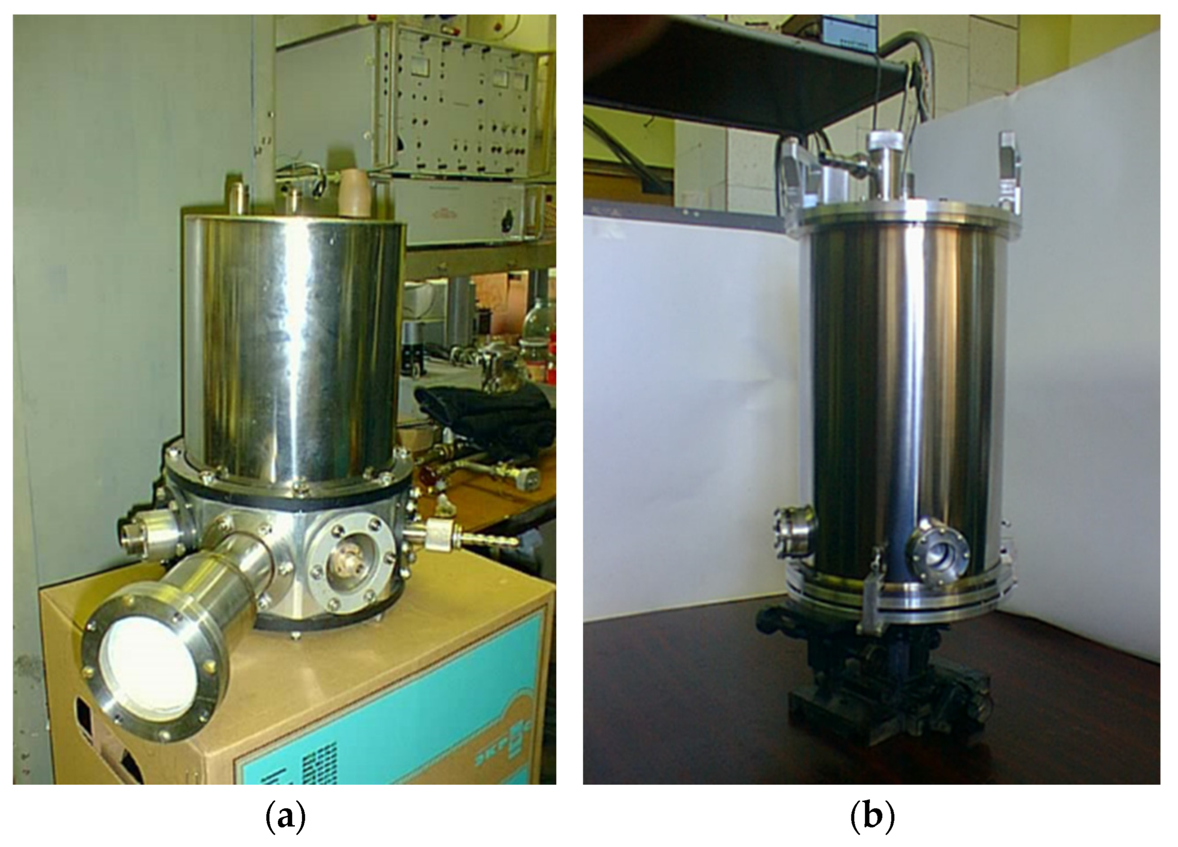
4.1. 4 K Cryostating Systems

An optical cryostat based on the Cryomech PT410 cryorefrigerator has been developed. It is designed for studying the thermophysical properties of materials (thermal coefficient of linear expansion, heat capacity, thermal conductivity), structures and mechanisms, and 4 K superconducting receivers, as well as for cooling samples and elements of the optical path with the possibility of using the Cryomech PT410 cryorefrigerator. A photo of the assembled cryogenic system and the system mounted on an antivibration rack is shown in Figure 12. This system has become practically replicable, and 5 similar versions have been created. As development progressed, it was possible to significantly improve the characteristics. An almost unprecedented result was achieved: one of the systems (among hundreds of cryostats made), which was created for the Institute of Microstructure Physics, achieved all the required performance characteristics immediately after assembly, without adjustments or modifications. A series of these developments has produced many interesting results for astronomy and space missions.
The main characteristics of the closed-cycle microcryogenic unit system (MCS) RDK-408D2 (SHI) with optional Cryomech coolers are as follows:
  • Operating temperature: 4 K ± 0.1 K; with a load: 0.8–1.5 W
  • Vacuum level: 10−4 mbar; flange KF D25 for pumping
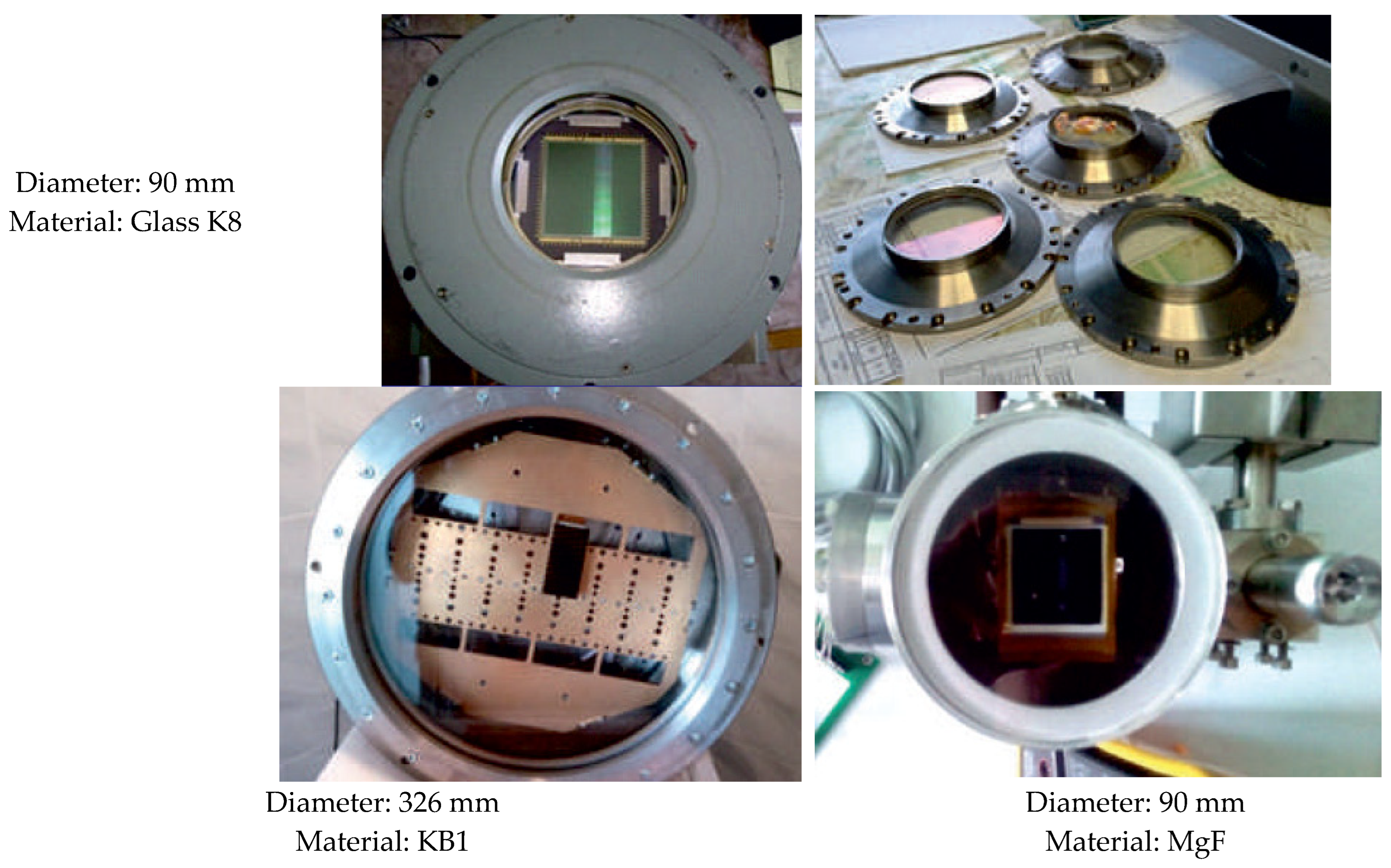
  • 2 flanges for installation of optical windows with a diameter of 25 mm;
  • Input of electrical and RF signals
  • Size of the working cavity: diameter 185 mm, height 70 mm, overall dimensions not more than 1600 mm; the diameter is not less than 700 mm; there are several options
  • A built-in interface for reducing the influence of temperature fluctuations with the possibility of observations when MCS is disabled
  • Availability of optical windows
  • The system should operate being installed on an antivibration rack
The main scientific results obtained using the equipment are as follows:
  • A prototype of the actuator that was designed for moving the main mirror of the Millimetron observatory at cryogenic temperatures has been tested already [60]. Photographs of the test sample are shown in Figure 13. Some results of the experimental studies are presented below
The following characteristics of the actuator have been confirmed experimentally:
-
Resolution in full-step mode: 0.64 μm;
-
Resolution in microstep mode (practically achievable): 0.3 mm;
-
Range of movement: ±3 mm;
-
Repeatability error: from 0.2 to 1.55 μm (0.8 μm, on average) in a range of 150 μm;
-
Minimum consumption power (continuous operation): 600 μW (T = 8...10 K);
-
Minimum consumption power when moving: 1 μm through 4 μW·s (mJ) (T = 8...10 K).
The research was carried out jointly by “Applied Mechanics” JSC and the Astro Space Center of Lebedev Physical Institute of the Russian Academy of Sciences (ASC LPI).
The result was that at ~10 K the temperature of the actuator-measured deviation was less than 0.6 μm and was true to type RMS at 18 μm.
2.
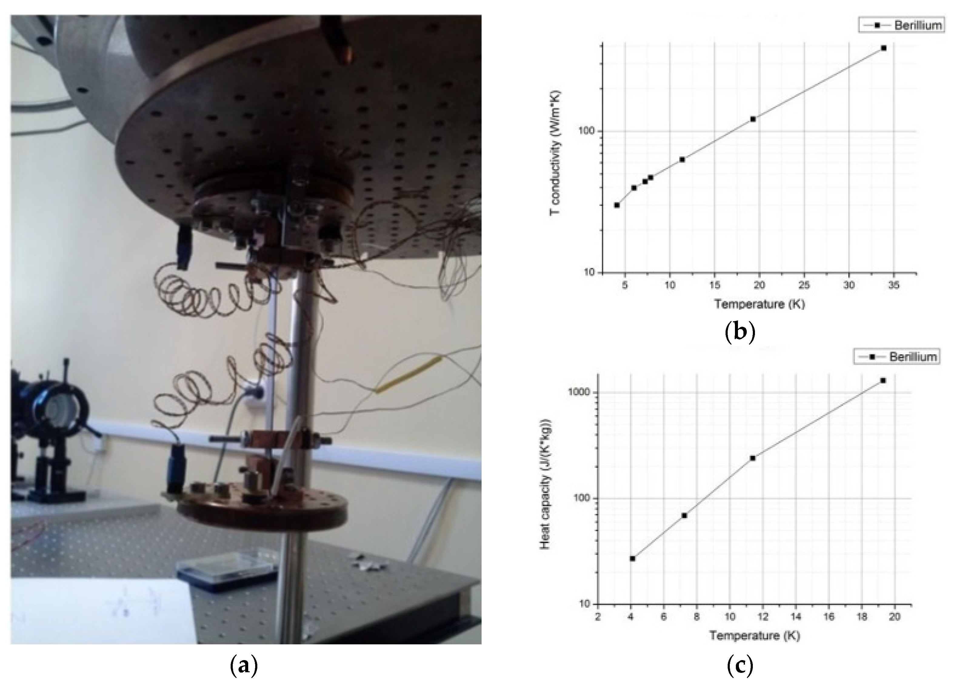
Measurements of the thermal conductivity and heat capacity of beryllium samples intended for the manufacture of the switching mirror of the space cryogenic telescope “Millimetron” were carried out.
A photograph of the mounted sample and the results of experimental studies regarding its thermal conductivity and heat capacity are shown in Figure 14.

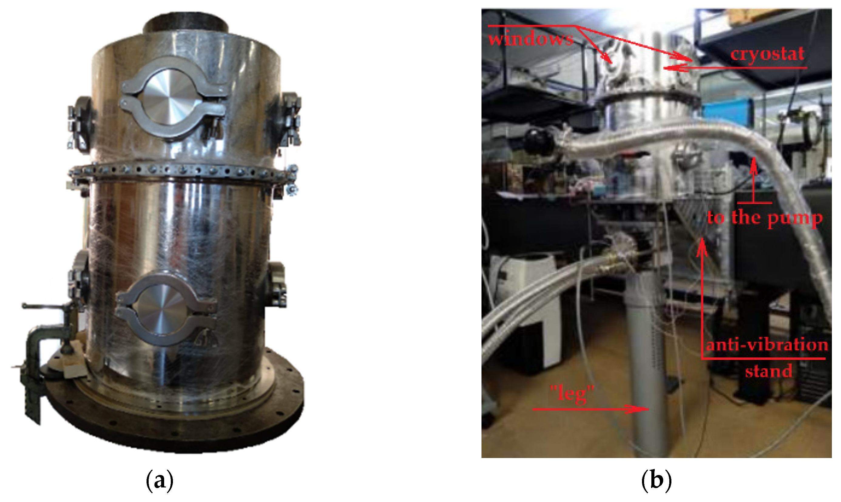
4.1.1. Solving the Problem of Vibrations and Temperature Fluctuations in Cryogenic Refrigerators

Refrigerator cooling systems, along with an extensive list of advantages, have a very significant disadvantage that limits their use for astronomical applications. Due to the periodic operation of the refrigerator cooler, temperature pulsations and mechanical vibrations occur. This is unacceptable when operating sensitive astronomical equipment. This paper presents the results of vibration studies and suggests some measures for reducing these negative effects.
The vibroacoustic effect of mechanical MCS parts has an interfering effect on detectors, amplifiers, measurement systems, etc. A low-temperature closed-cycle cryorefrigerator refrigeration unit was selected as the test object for studying vibration levels. The purpose of the test was to measure the vibration levels created by the hardware at the points of the intended location of the tested and reference sensors. The tests were carried out using the following equipment:
  • Accelerometers B&K 4371-2
  • Charge amplifiers B&K 2651-2
  • Power supply B&K 2805
  • 2-channel ADC M-AUDIO Transit
The measurements were carried out at room temperature (thermal insulation shells were not installed on the installation). Two accelerometers with synchronous recording of signals on a laptop computer were used for measurements. One sensor was placed at the intended location of the electromagnetic radiation receivers on a low-temperature plate inside the working area of the installation. The second accelerometer was placed consecutively near the main sources of vibration activity included in the stand. The signals were recorded under three different modes of operation of the installation:
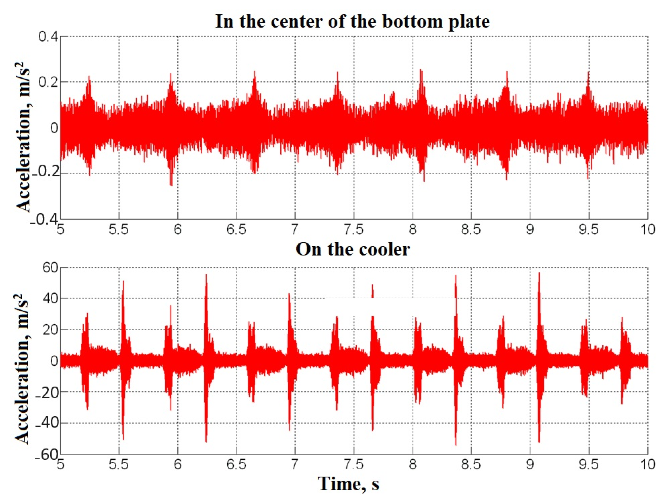
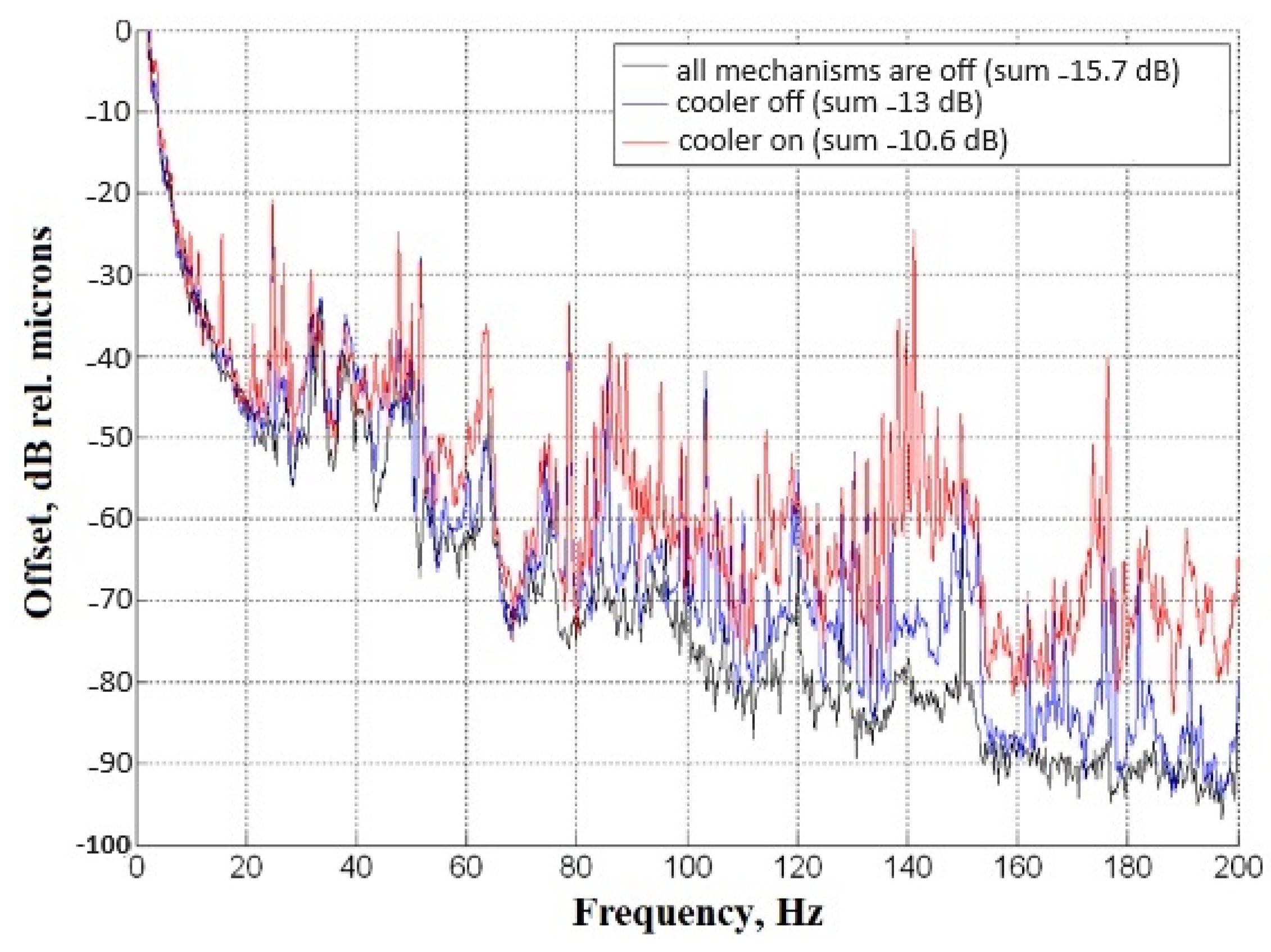
  • All mechanisms were disabled (recording duration ~60 s).
  • All main mechanisms (the pumps and compressors) were turned on; the cooler was turned off (recording duration ~60 s).
  • All main mechanisms (the pumps and compressors) were “on”; the cooler was “on” (recording duration ~30 s).
Figure 15 shows an example of the time realizations of the vibration acceleration signal measured at the points at the center of the lower plate inside the working area of the installation and on the cooler during its operation. Figure 16 shows the amplitude spectra of vibration displacement at the same control points obtained by averaging over 30 samples with a length of 1 cm.
The excitation signal is a sequence of short pulses with a repetition period of about 0.6 s. The lower graph (Figure 15) corresponds to the spectrum of the source of the exciting force. The upper graph (Figure 15) illustrates the frequency dependence of the response to the impact from the cooler in the working area of the installation.
The graphs in Figure 16 demonstrate good vibration isolation of the load-bearing structures located inside the working area of the installation from the main vibro-active sources of the stand in the range above 1 kHz. The nature of the cooler operation determines the signal in the form of successive pairs of pulses. The pulses alternate along the carrier frequency, which is clearly seen in Figure 15, where only the low-frequency ones are visible (suppression of about 150 times), and the high-frequency ones are almost completely absorbed by the vibration isolation (suppression of at least 500 times).
The low-frequency range is the most energy-intensive and dangerous in terms of vibration displacement amplitudes. Figure 17 shows the averaged amplitude spectra of vibration displacement at the control point at the center of the lower plate in the working area of the installation in the 0–200 Hz range. The spectra were obtained by averaging 6 samples of a signal with a duration of 5 s. In the low-frequency range, the response at the control point is a set of discrete components that were created during the operation of the cooler (140 Hz, 176 Hz, etc.) and other installation mechanisms (24.8 Hz, 51.8 Hz, 78.8 Hz, etc.).
As can be seen from Figure 17, at this point of the plate the level of each narrow-band component individually does not exceed 0.1 μm. The integral level of the vibration displacement amplitude in the 8–200 Hz band is given in the legend of the graph and is ~0.3 μm when all the mechanisms of the installation and the cooler were working.
The frequency resolution of the spectra shown in Figure 17 is 0.2 Hz. The width of the discrete components is significantly smaller, as can be seen from Figure 18, which shows the amplitude spectra at the control point on the lower plate obtained at different frequency resolutions.
The sufficiently high level of the intrinsic noise of the measuring channel used at this stage and the limited registration time did not allow for reliable measurement of the vibration spectrum in the range near zero frequencies. It was possible to extend the frequency range into the low-frequency region using accelerometers with a built-in amplifier. It was also recommended to consider the possibility of using an optical vibration measurement method (laser vibrometer), which is operable, in particular, at the operating temperature of the object.
Attention should be paid to the unevenness of the vibration level on the low-temperature plate where the receiver was located. Figure 19 shows the averaged amplitude spectra of the vibration displacement for the two control points at the center (red curve) and the edge (black curve) of the lower plate in the working area of the installation. The vibration levels in the narrow frequency bands could differ by ~20 dB at different points of the plate, and the integral levels, by 6 dB.
Since the equipment was installed on the 10th floor, where the cryogenic nanoelectronics laboratory is now located, the studied samples show the influence of people and buses passing nearby. During the measurements, a significant influence of external interference in the room on the measurement levels was noted, which is due to the lack of measures taken to vibro-isolate the installation from the floor where it was placed.
Based on the results of the vibration tests of the stand, the following conclusions can be made:
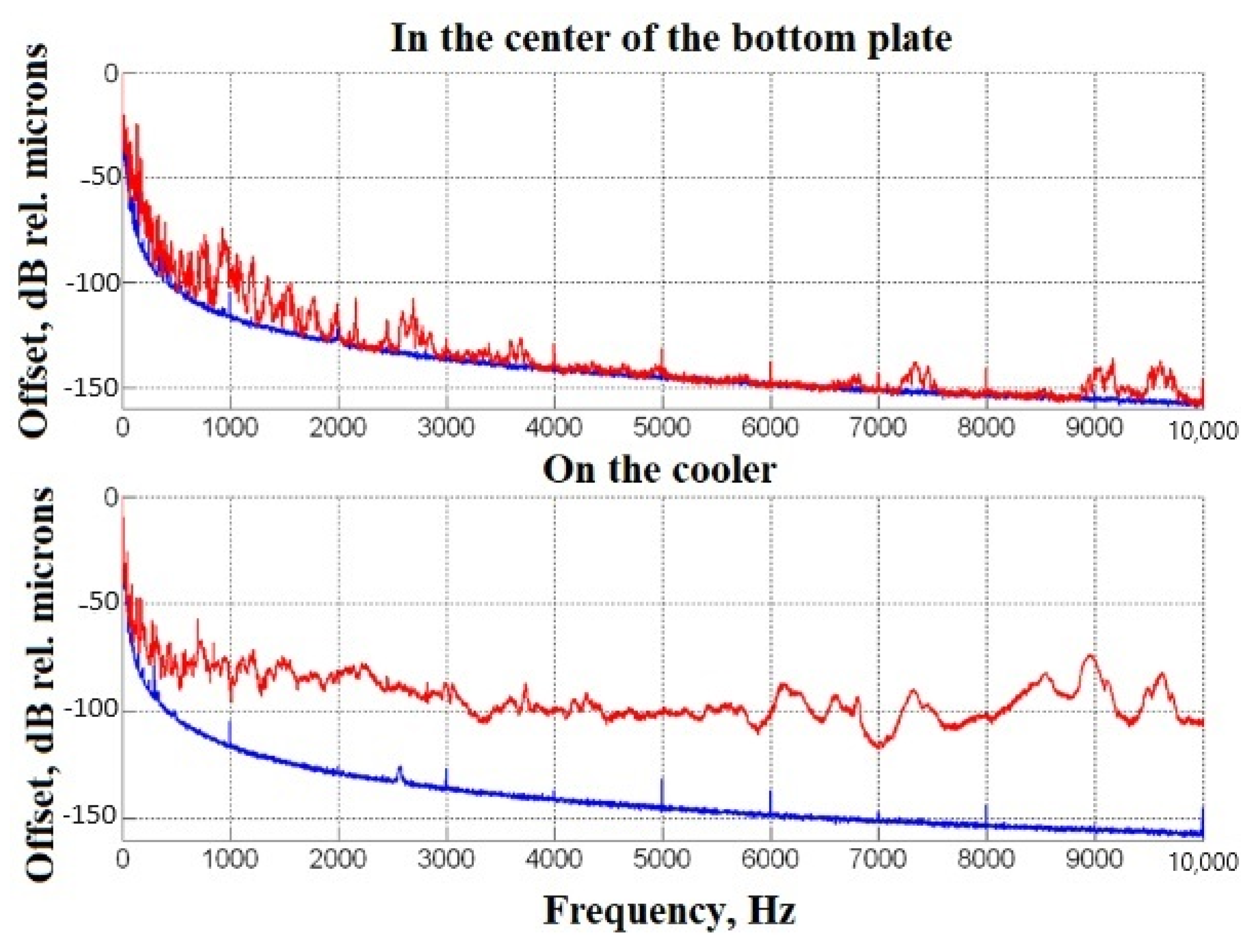
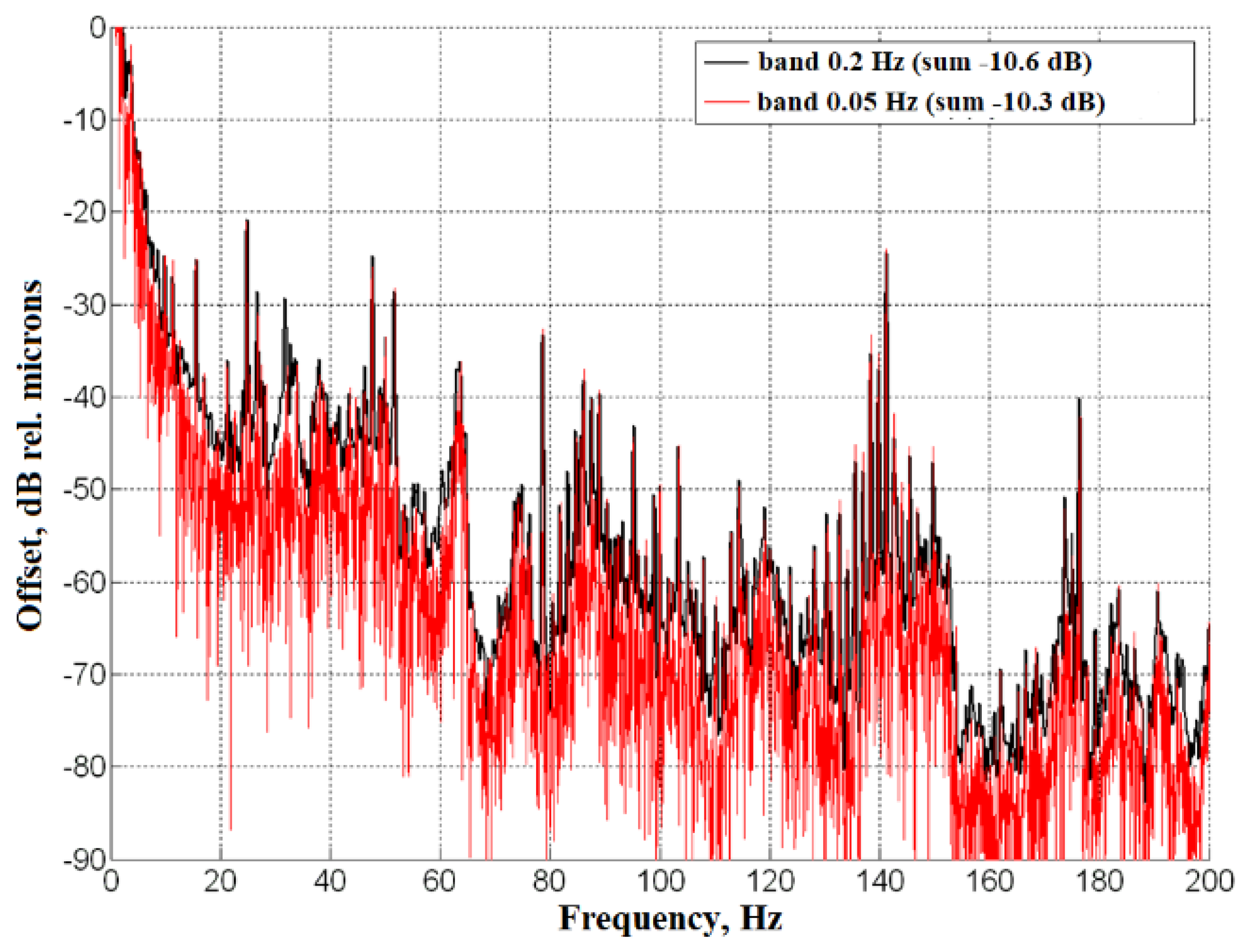
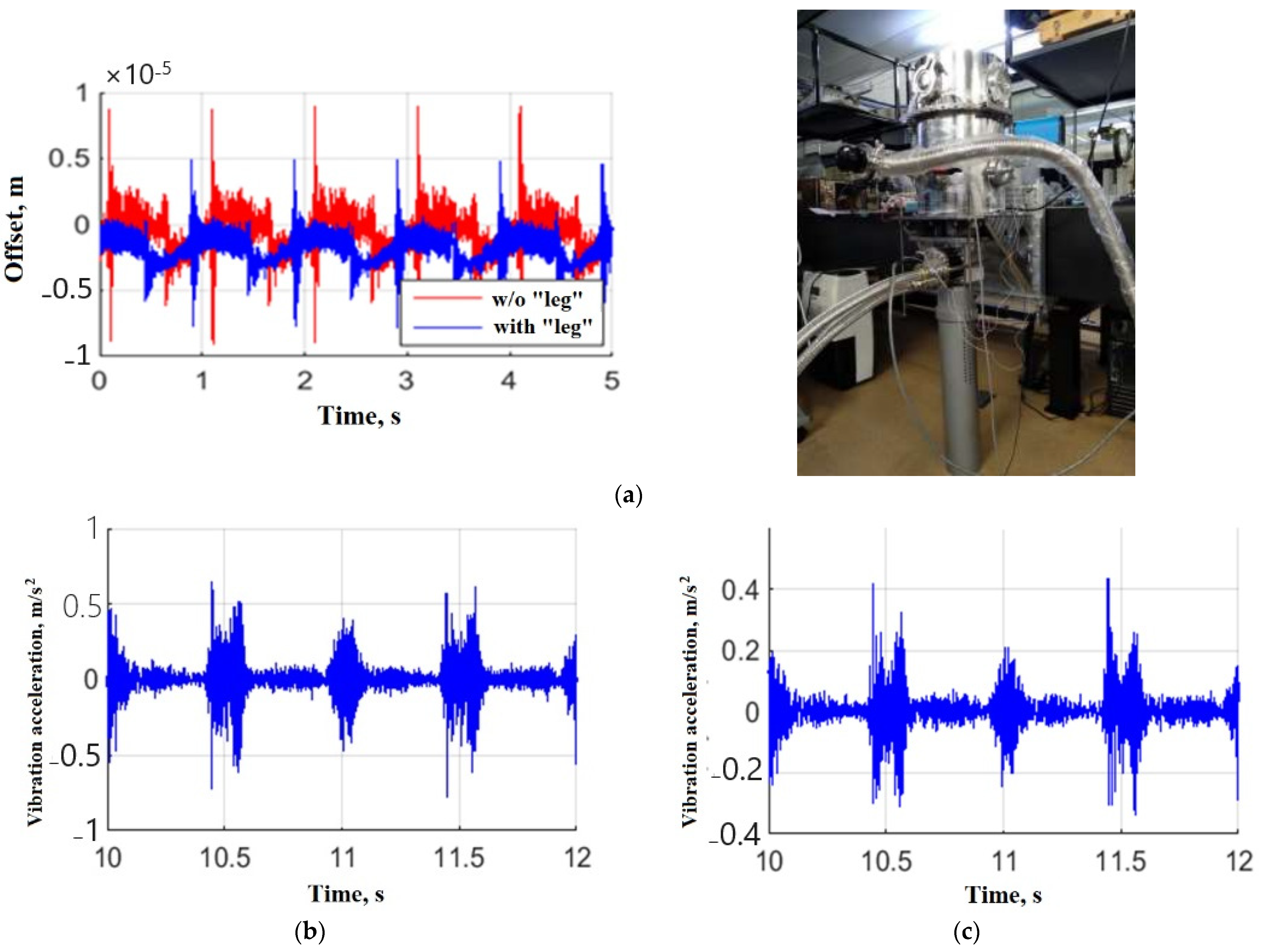
  • The vibrations in the working area were determined by the periodic action of the cooler, and the width of the discrete components of the vibrations was obviously <0.1 Hz.
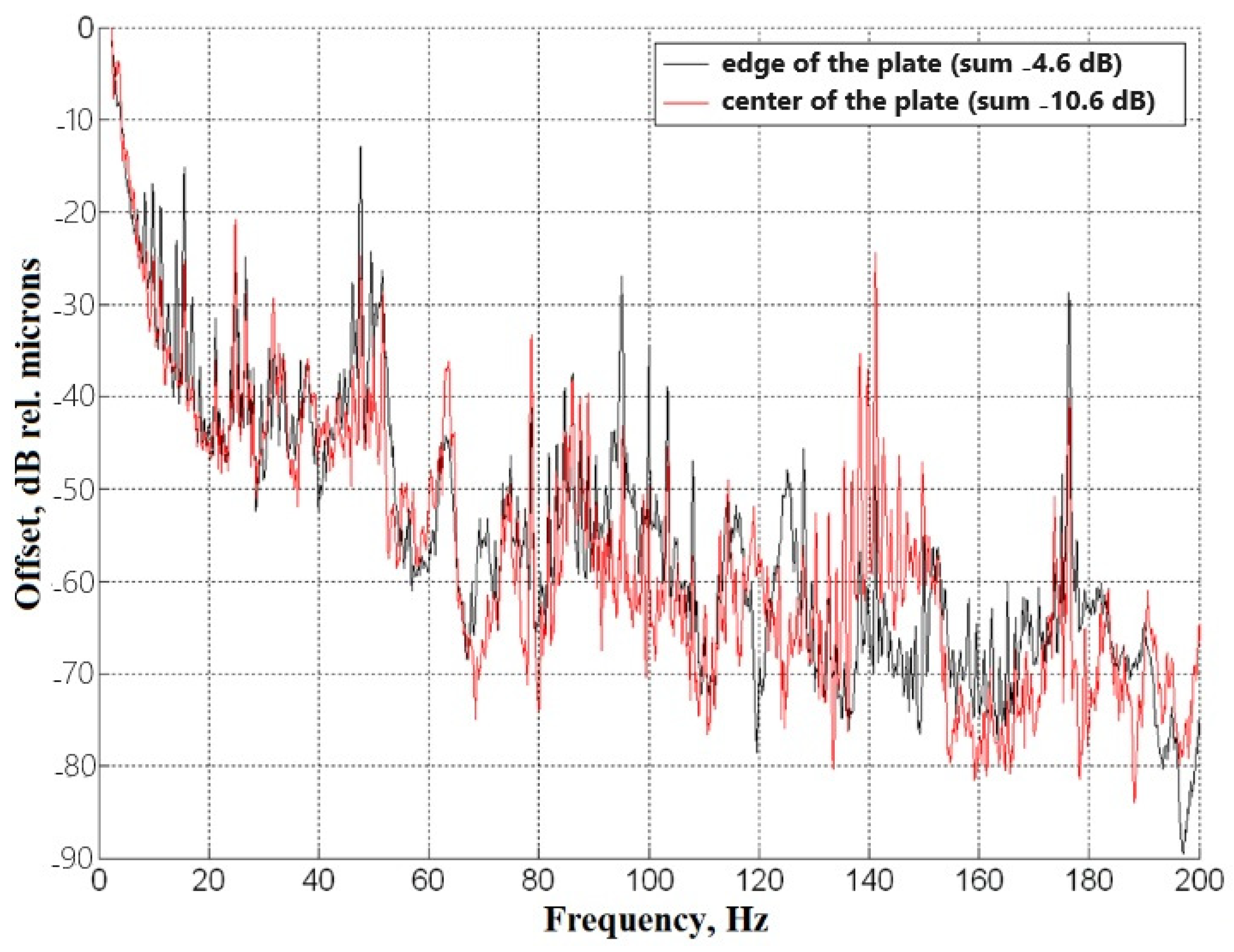
  • The vibration displacement levels of the narrow-band components at the control points on the lower plate in the working area of the installation did not exceed 0.22 μm (<0.1 μm in the center of the plate). The integral level of vibration displacement in the 8–200 Hz band ranged from 0.3 μm to 0.6 μm at different points of the plate.
  • To provide measurements in the frequency range of 0.5 Hz, it is recommended to use a laser vibrometer. It is also recommended to evaluate its measuring capability at the operating temperatures. The measurable levels achievable by using standard laser vibrometers will be no worse than 100 nm up to zero frequencies.
  • To develop recommendations for reducing the vibration level of the structure in the working area of the installation, a more detailed measurement of the acoustic vibration characteristics of the stand (transmission coefficients from the source to the working area) should be carried out, and measures should be taken to ensure vibration isolation of the installation as a whole. For the following measurements, a measuring path with a lower noise level should be used.
  • Of course, for the final verification of the data obtained, it is useful to conduct a test during cooling; for this, it is necessary to provide thermal and vacuum isolation of the measuring equipment, since the individual parameters, in particular, heat capacity, thermal conductivity, sound propagation velocity in the medium can vary depending on the temperature.

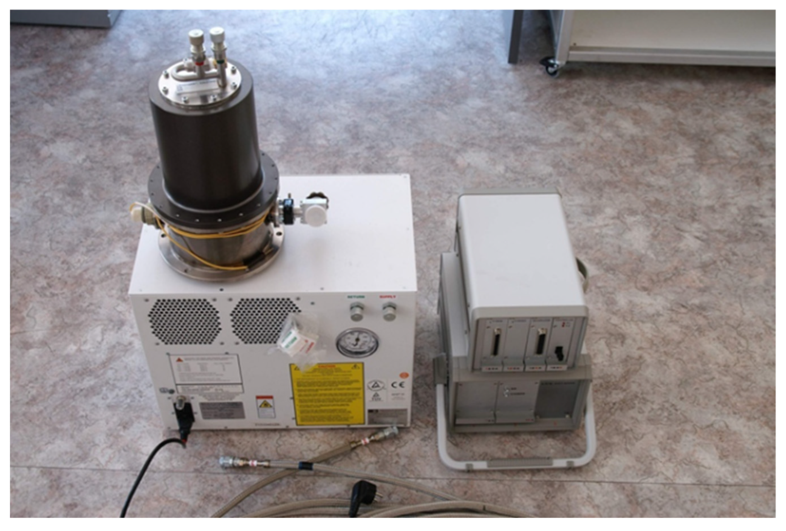
4.1.2. Antivibration 4 K Cryostating System

The closed-cycle cryostating system with a reduced level of mechanical vibrations (vibration damping system) is designed to study samples of highly sensitive superconducting detectors, including not only THz but optical too. Photos of the cryosystem are shown in Figure 20. As a basic configuration (prototype), the 4 K system presented in the previous section was used. The vibration damping system includes the both design solutions and a specially designed structure of cooling pipes and screens, which soften the mechanical contact integrally, which leads to deterioration in the transmission of acoustic waves or vibration damping. Experiments have shown that the vibration damping system makes it possible to reduce the vibration level of the cryosystem panel, on which the elements of the receiver detector are supposed to be placed, by 7–8 dB in comparison with the vibrations of the basic configuration system. The vibration displacement level of the prototype ranged from 50 to 150 μm. In the experiments of this cycle, the vibration level did not exceed 1 μm, and was almost an order of magnitude lower than the requirements of the terms of reference and the measurement metric program, which is obviously sufficient for receiving systems of sub-Hz waves, where the criterion for the negligibility of the vibration effect is A_ν = λ/20 (here, A_ν is the vibration amplitude and λ is the wavelength).
The main characteristics of the system are:
-
Operating temperature: 4 K ± 0.1 K; with heat load: 1 W;
-
Vacuum level: 10−4 mbar;
-
Vibration displacement of the 4 K plate in the horizontal plane: no more than 10 μm;
-
close-cycle MCS RDK-408D2 (SHI), mounting of MCS: cold head up
-
4 flanges KF D50 for mounting of optical windows with a diameter of 50 mm (optional), 3 flanges KF D50 or the mounting of electrical and RF connectors;
-
Working cavity size: diameter 200 mm, height 90 mm;
-
Overall dimensions of the product: diameter 400 mm, height 800 mm.
Additional options for the basic configuration are the presence of a vibration damping system, quick access to test samples and the possibility of quick installation of various equipment on 8 KF50 flanges.
Vibrations of cryogenic systems
Cryosystems with refrigerators based on pulse tubes are used for long-term experiments. The main disadvantage of such systems is the additional mechanical noise, which contributes to the general noise of receiving systems, which must be reduced in the case of high-precision/high-sensitivity experiments. There are various mechanisms for suppressing such noise vibrations, for example, compressor decoupling, damping pads, etc. The 4 K level cooling system with the vibration damping system, which was developed by the authors of this paper, has been presented above.
The problem of damping the vibrations of the refrigeration unit was resolved using both the special features in the design of the elements of the case and the layout of the cryostat, and the special design of the cold pipes and screens, which generally soften the mechanical contact, leading to a decrease in the transmission of acoustic waves or vibration damping. But this obviously cannot but affect the heat transfer mechanisms and even vacuum conditions, which can lead to undesirable consequences in the cooling characteristics of the receiver. In fact, a compromise is required between achieving the required thermal and acoustic performance. Vibration measurements of the sample simulator were carried out with a laser vibrometer in the horizontal direction. The laser beam was directed at the sample through an optical window in the housing. The cryosystem was mounted in a clean room on the optical table of the PEARL-10 multi-petawatt laser stand (see Figure 21a, right). The compressor with a capacity of 7 kW was installed in an adjacent room (with a separate foundation and no requirements for the cleanliness of the room) and connected to the cryostat and cooler by flexible metal hoses laid into the clean area of the silo, where the cryostat was located.
After a successful vibroacoustic test, the cooling capacity and the maximum achievable temperature of the cryostat design upgraded from the point of view of acoustics were checked. As expected, the nominal characteristics of the cryostat were not achieved during the first test. The computational, theoretical, and experimental works were carried out to find the compromise mentioned above [2,3,25,40]. The main measures to achieve the nominal temperature in 4 K were as follows:
-
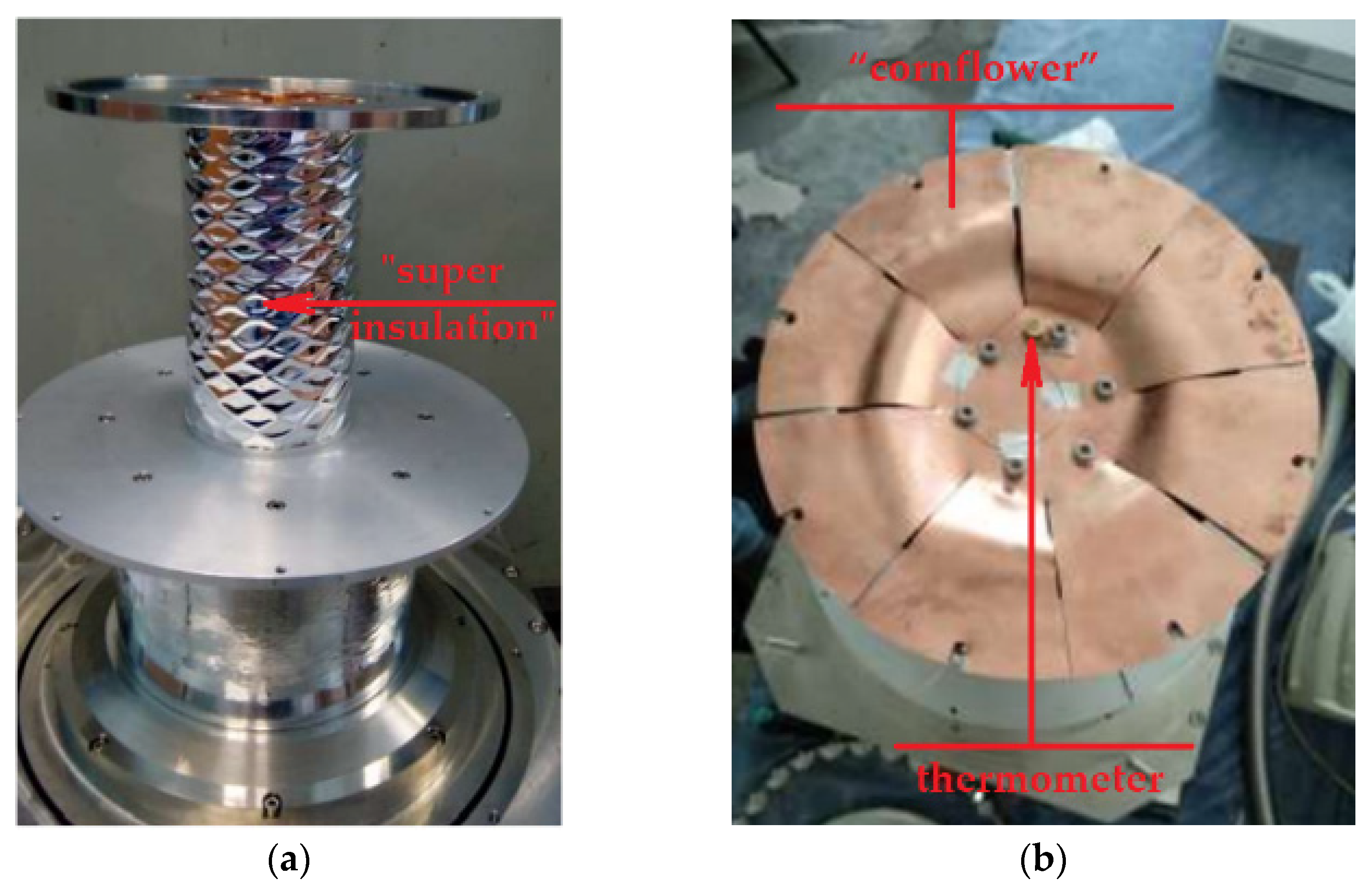
To reduce the 4 K radiation losses, the support was covered with superinsulation (Figure 22a)—an additional cooling line made of a spring ring of soft annealed copper was installed under the 4 K panel and on the cold finger of the cryomachine to improve heat transfer between them (“cornflower”) (Figure 22b). A great deal of this work regarding this element of the process has been carried out on microphonics and their treatment.

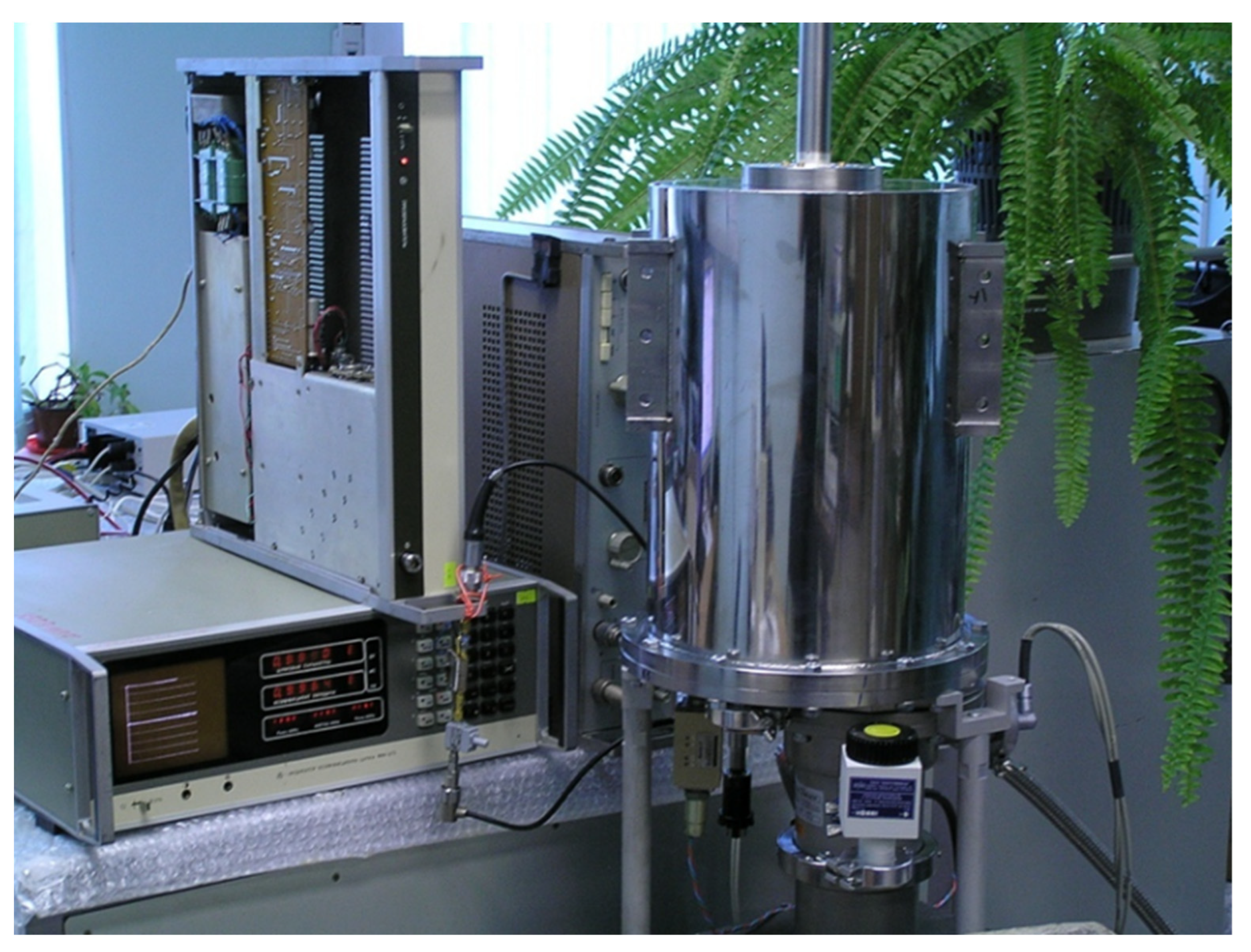
4.1.3. The Low-Vibration 4 K Cryostating System for Studying Thermal Deformations of the Panels of the Main Mirror of the Millimetron Space Mission at Cryogenic Temperatures

Together with the ASC LPI, a cryovacuum chamber was created for studying the thermal deformations of the panels of the main mirror of the “Millimetron” space telescope. A photo of the cryosystem is shown in Figure 23.
The main characteristics of the system are:
  • Operating temperature: 4 K ± 0.5 K
  • Residual pressure inside the cryostat: 10–5 mbar
  • The level of vibration displacements on a cold plate: no more than ±0.5 μm in the frequency range up to 300 Hz
  • Vacuum inlets: 32 fiber optic, 2 KF25, KF16, and an optical window
  • Overall dimensions: height 1450 mm, diameter 830 mm

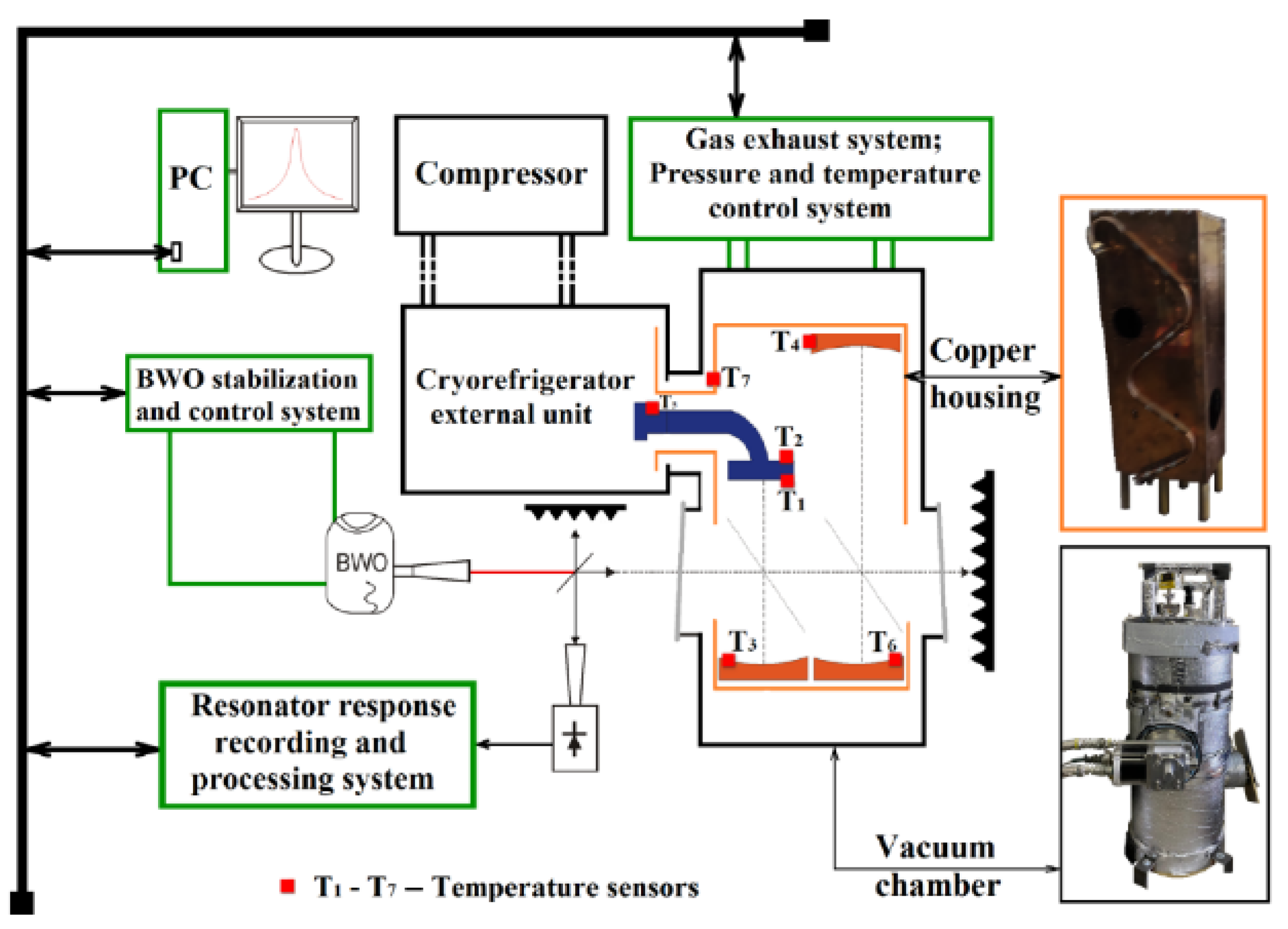
4.1.4. Cryovacuum Resonator Complex

The cryovacuum resonator complex [61,62] (see Figure 24 and Figure 25) is a unique new-generation laboratory hardware system for studying the dielectric parameters of gases and condensed matter (in the temperature range from −50 °C to + 200 °C), as well as the reflectivity of surfaces (reflection losses) in the frequency range from 100 to 520 GHz, and the pressure range from 10−3 Torr to atmospheric pressure at temperatures of 4–370 K. The radiation loss in the investigated substance determines the Q factor of two quasi-optical Fabry–Perot resonators located in the vacuum chamber. The length of the resonators differs by half: the long (symmetrical) resonator is formed by two identical spherical mirrors, and the short (asymmetrical) resonator is formed by one spherical and one flat mirrors. Deep cryogenic cooling (up to 4 K) is used to conduct reflectivity studies. A symmetrical resonator is used as a reference, and a test specimen of the reflector is mounted on the flat mirror of the asymmetric resonator. For thermal isolation from the resonator housing, the mirror with the specimen is fixed on fiberglass racks and is connected to the second stage of the cooler by a flexible cooling wire. The copper housing is connected to the first stage of the cooler and is also isolated from the chamber walls. The temperature deviation along the length of the housing does not exceed two degrees at 70 K. As the cryogenic basis of the equipment, a cryovacuum chamber with a closed-cycle RDK-415D cryorefrigerator manufactured by Sumitomo Heavy Industries, Ltd. with a Gifford–McMahon thermodynamical cycle of the helium temperature level is used. This refrigerator is able to provide cooling without a load to a temperature below 3 K in the second stage and up to 60 K in the first stage.
Also, the experimental setup is used in the temperature range from −50 °C to + 200 °C to study the spectra of gases. However, in this article, we will not consider this research line because no deep cooling is provided in this mode, only down to −50 °C (more details can be found on the website of the Department of Microwave Spectroscopy of the IAP RAS—URL https://mwl.ipfran.ru/#/ (accessed on 3 March 2024). Recently, a new vacuum chamber has been developed and manufactured for such studies (see Figure 26) in order to increase the number of experiments.
The chamber is equipped with a pressure and temperature monitoring system and is thermally insulated from the external environment. The vacuum system provides metered injection and pumping of gases. The temperature of the mirrors, the casing, and the sample is controlled by the automated LakeShore Temperature Monitor system (the sensors are marked T1–T7 in Figure 24).
Main characteristics of the equipment are as follows:
  • Frequency range: 36 ÷ 520 GHz
  • Temperature range for gases: within 220–370 K with the possibility of long term stabilization at any temperature, within 10–220 K without temperature stabilization, and 4 K–900 K for dielectrics and metals
  • Gas pressure: 0–1500 Torr
  • Sensitivity to changes in absorption in gas: ~0.001 dB/km (4 × 10⁻⁹ cm−1)
  • The range of measured values of the refractive index: 1–10 with a relative error up to 10−4
  • Measured thickness of the dielectric plane-parallel plates: 0.002–30 mm with an accuracy of up to 10−4
  • Minimum diameter of the solid sample under study: ~12 mm (on 140 GHz)
  • Range of measured values (tgδ): 10−2 ÷ 10−7 with a relative error of up to 5%
  • Range of measured values of reflection losses: 10−1 ÷ 10−4 with an average relative measurement error ~5% at the level of reflection losses ~10−3
The main scientific results obtained with this equipment
A wide class of metal coatings for antennas of ground-based and space-based radio telescopes has been studied for the creation of highly sensitive cooled receivers. The reflectivity of mirrors with different internal structures made of ultrapure silver, copper, gold, aluminum [63], and beryllium alloy [63] has been studied. It has been shown that when specimens are cooled to the liquid helium temperatures, the reflection losses vary significantly depending on the structure of the surface of the reflecting layer and the presence of impurities, and a limit for reducing reflection losses is found. Reflection losses have been investigated for the film reflectors of the Millimetron Space Observatory [61].
The prospects of using materials with high-temperature superconductivity (HTS) [64] as well as classical superconductors of the second type based on Nb and NbTiN [62] are shown. Data on the losses of reflection of millimeter waves by these materials were obtained for the first time.
The dielectric properties of a wide class of dielectrics and semiconductors (crystals, ceramics, amorphous substances, plastics, etc.) have been studied. These studies have made it possible to create a reference database for the selection of materials used. In particular, a cycle of studies of dielectrics with ultra-low absorption in the millimeter and submillimeter ranges for the input and output windows of megawatt generators (within the framework of the ITER program) has been carried out. Based on the research performed, thermal calculation of the windows based on CVD diamonds for the output and input of heavy-duty radiation has become possible. A class of dielectric liquids which have a great potential for cooling energy output windows in high-power and heavy-duty generators of the millimeter and submillimeter ranges has been determined.
The main result of the research performed is to obtain data on the radio and thermal physical properties of new materials and composites used for cryogenic receivers, antennas, and other systems of astronomical radio telescopes. The data obtained were used in the design of the Millimetron space mission.

4.2. CCD Matrix Cooling Systems

CCDs (charge-coupled devices) are used in many areas, both in fundamental science and in military and astronomical applications. As mentioned in the introduction, one of the most effective ways to reduce noise characteristics and consequently increase the sensitivity of the receiving device is to cool the device itself. Nitrogen-level cooling (~80 K) is also quite popular for optical and infrared photodetectors [65,66]. In this subsection, we will present only a short description of the cooling device for CCD, while the lineage of CCD array cooling systems developed for BTA SAO RAS was presented in our previous paper [40]. However, for some CCD matrices, “soft” cooling up to −40 °C is usable [67].
Based on accumulated experience, specialized chambers were manufactured for cooling CCD matrix in the vacuum ultraviolet range with a temperature range from 80 K to 230 K. Since ground-based observations cannot be made in this range, it is assumed that it will be used for the Spectrum -UV space mission. Also, a cryogenic test system was created for cooling several objects with gaseous or liquid nitrogen to simulate the conditions of deep space, where the cameras manufactured for cooled CCD matrix of the VUV range were tested. This is a system consisting of a nitrogen Dewar vessel, insulated metal hoses, the interfaces for supplying cold to consumers, and a temperature control and stabilization unit. The characteristics and photos of the systems are given in Table 2.

4.3. Components of Cryogenic Astronomical Receivers That Are out of the State of Thermodynamic Equilibrium

A mandatory element of cryogenic systems for receiving devices is a sealed optical window (for signal input to the detecting cell), and often there are thermally coupled waveguide and quasi-optical lines inside the systems that supply the signal to a deeply cooled device (amplifier, mixer, detector). For the first time, these issues were addressed in publication in [68]. As noted above, these elements are characterized by the fact that they are not in a state of thermodynamic equilibrium, and strictly speaking, even the term “temperature” is not applicable to them without reservation. The related features in the calculation, analysis, and design of such systems are discussed below.

4.3.1. Physical Temperature and Noise of a Sealed Window

The task of analyzing and creating a cryoreceiver window is reduced to constructing a vacuum-dense and transparent entrance for the received radiation with a minimum of parasitic heat flows inside the cryostat. The heat flux and the temperature distribution over the window surface are calculated based on the thermal conductivity Equation (3):
x   k T x + y   k T y + z   k T z + q x , y , z = C p ρ T τ ,
where x, y, z are the Cartesian coordinates, q is the heat source, Cp is the heat capacity, and ρ is the thermal conductivity of the material. As a result, it was found that under certain conditions, the temperature of the central zone of the window can differ quite significantly from the ambient temperature (by 5–15 K). At the same time, it is very likely that the temperature of the outer surface will be below the dew point for a certain range of ambient temperature and humidity, which will inevitably lead to the precipitation of water condensate, and that is extremely undesirable due to the significant absorption of water waves in the 0.1–1 THz range. The presence of an infrared filter [69] between the cold receiver input and the window improves the picture significantly. The infrared filter, which is a layered or loose structure fixed on the radiation screen of the cryostat, absorbs most of the radiation from the heated environment lying outside the band of received signals. Along with undesirable condensation, radiation cooling of the window has positive consequences: the colder central zone of the window, through which the received signal mainly passes, has slightly lower temperatures and losses. As a result, the overall noise temperature of the receiver decreases. Based on the obtained temperature distribution, in [68] the transfer equation is solved and a refined noise temperature is obtained, which is 5–7% less than the calculated one without cooling for the implemented configurations of windows and receivers.
Another important feature when designing a cryogenic system is that the larger the optical window is, the greater the thermal load becomes. For example, with a window diameter of about 100 mm and a background load of 300 K, the external power is about 9.5 watts. Various combinations of radiation filters, such as Zaytex, Fluorogold, HDPE, etc., are used for the solution.
The authors of the article have achieved success in the installation and operation of hermetic optical windows having various diameters (including “extra-large” ones) and made of various materials. Some examples are given in Figure 27.

4.3.2. Dissipative Transmission Line at the Temperature Drop

In addition to the window, a specific element of the cryogenic receiver is an incoming thermo-decoupling feeder, which, however, is sometimes absent if the horn of the antenna irradiator is placed inside the cryostat. The thermally coupled waveguide in the millimeter and submillimeter wavelength ranges is usually supersized and sometimes combines the function of transition to the main section of the waveguide. Here, we also solved a problem similar to the one discussed in the previous section. Specifically, the temperature distribution profile along the length of the line is determined on the basis of the thermal conductivity equation [68]. Knowing that the loss factor depends on the conductivity and the size of the waveguide, we can determine the attenuation constant as the product of the factor by the linear function D(λ) of the working wavelength. The calculated distributions of the temperature and specific losses along the length of the line allow us to solve the transfer equation uniquely [70] for it and calculate its noise temperature (9):
T n = 0 X T a l ( x ) e x p 0 X l ( ξ ) d ξ d x ,
where 0 and X are the coordinates of the waveguide ends, Ta = Ta(x) is the law of distribution of the physical temperature along the length of the waveguide established from the solution of the equation of thermal conductivity, and l(x) is the law of distribution of losses in a waveguide of a given section.
Another issue is the definition of the three-dimensional heat flux in a waveguide active device. The equation of thermal conductivity with allowance for the internal heat source was solved to estimate the temperature of an active device placed in a waveguide chamber. This configuration is typical for converters and amplifiers of millimeter and submillimeter waves. Consider the three-dimensional problem of thermal conductivity for a model of a cubic device cooled from one of the faces ( T | x = L = T 0   ) and located in vacuum without heat transfer along the remaining faces (dT/dx | x = 0  = 0; dT/dy | y = 0 , L  = 0; dT/dz | z = 0 , L = 0), with an internal heat source q having a heat dissipation characteristic of a diode (transistor) and characteristic dimensions l being approximately 2 orders of magnitude smaller than the external size L of the device (waveguide chamber). In this case, the distribution function of the source along the x coordinate has the form:
Q x = f x =       0 ,   x L 2 > l / 2 q / l 3 ,   x L 2 l / 2
For the rest of the coordinates, the distribution of the heat source is recorded similarly. Let us write the function
U m n k x , y , z = c o s m π L y c o s n π L z c o s 2 k + 1 L π x
satisfying the boundary conditions described above. Here, we introduce a variable t equal to the difference between the physical temperature and the temperature of the cooled wall, coupled with a cooler of conditionally infinite cooling capacity, while t | x = L = 0 and dt/dn = 0. We define the Laplace operator of the Function (11)
Δ U m n k = π 2 L 2 m 2 + n 2 + 2 k + 1 2 2 U m n k
The solution of the thermal conductivity equation can be written as:
V x , y , z = m , n , k = 0 V m n k U m n k ( x , y , z ) ,
where
V m n k = ( 2 / L ) 3 0 L 0 L 0 L U m n k ( x , y , z ) V ( x , y , z ) d x d y d z .
Solving the system of Equations (12)–(14) with respect to t, one can find the temperature of the source at the center of the cube analytically, without using numerical methods:
T c = t + T 0 = t + N f q / ( k l )
Here, N f is the the form factor. For the “small cube in a large cube” model with a 1:100 aspect ratio, the form factor is N f = 0, 19.
Calculation (15) shows that the overheating of a standard planar millimeter-wave Shottky barrier diode in vacuum can reach 10–13 K, with heating up to 10 K due to the contribution of the planar structure itself.

5. Conclusions

This paper provides a brief overview of the principles of operation, basic designs, and features of the design and manufacture of cryogenic systems of various temperature levels used to cool detection devices of various frequency ranges for astronomy and other applications. The specific features of the cryodesign of such systems are considered: methods for thermal calculations of cryostats of various temperature levels for astronomical receivers were proposed, the fluctuation characteristics of refrigerators and their vibration were studied, measures were proposed to reduce the influence of these negative processes on the characteristics of the receivers, and original designs of optical inputs to cryostats with extremely low losses of the useful signal were proposed. Also, some transfer issues of radiation in a signal transmission channel that is nonstationary in temperature were considered. The main result of the article is the presented development of an extensive range of cryogenic astronomical equipment for different observatories. Based on these developments of both optical (photonic) and radio-astronomical (electronic) equipment, a new project by the authors of the article is being built to develop receiving equipment in the intermediate terahertz range for new telescopes that are expected to be built in northeastern Eurasia (the Caucasus and Siberia in Russia [71], Uzbekistan [72], and China [73]), or, for example, within the framework of the EHT project expansion program [74]. These observatories will be certainly equipped with cryogenic receivers based on the experience described in the article, and there is a close collaboration with international teams involved in the development of the above-listed observatories. The work not only summarizes the results of development of a series of cryogenic receivers for various observatories, but also presents a set of original technical solutions for both the cryogenic systems themselves and various interfaces that provide efficient cooling with a minimum of negative impacts of cryogenics on the operation of the receivers.
The work can also serve as a kind of a manual for designers of cryogenic systems for astronomical receivers of various wavelengths.

Author Contributions

Conceptualization, V.V.; methodology, Y.B., V.E., M.T., A.C. and S.S.; software, O.B. and I.L. (Ilya Lesnov); validation, M.E. and A.S.; formal analysis, M.M. (Mariya Markina); investigation, A.E., A.G., A.K., A.V., I.L. (Igor Lapkin)., S.S., M.M. (Mariya Mansfeld), M.M. (Mariya Markina); N.T. and E.P.; data curation, I.L. (Ilya Lesnov); writing—original draft preparation, A.G. and V.V.; writing—review and editing, V.V., A.G., A.V., M.E. and S.S.; supervision, V.V.; project administration, A.V.; funding acquisition, Y.B. and V.V. All authors have read and agreed to the published version of the manuscript.

Funding

This work is supported by the grant of the Russian Science Foundation # 23-79-00006.

Institutional Review Board Statement

Not applicable.

Informed Consent Statement

Not applicable.

Data Availability Statement

New scientific data obtained as part of the presented research are presented in the scientific report on the RSF project # 23-79-00006for 2023 and can be obtained on the website of the Russian Science Foundation https://rscf.ru/en/.

Acknowledgments

Cryogenic systems were manufactured on the basis of UNU No. 3589084 “CKP-7—Center for Microwave Research of Materials and Substances”.

Conflicts of Interest

The authors declare no conflicts of interest.

References

  1. Ladu, A.; Schirru, L.; Gaudiomonte, F.; Marongiu, P.; Angius, G.; Perini, F.; Vargiu, G.P. Upgrading of the L-P Band Cryogenic Receiver of the Sardinia Radio Telescope: A Feasibility Study. Sensors 2022, 22, 4261. [Google Scholar] [CrossRef]
  2. Murzin, V.A.; Markelov, S.V.; Ardilanov, V.I.; Afanaseva, T.; Borisenko, A.; Ivashchenko, N.; Pritychenko, M.; Mitiani, G.; Vdovin, V. Astronomical CCD systems for the 6-meter telescop BTA (a review). Appl. Phys. 2016, 4, 500–506. (In Russian) [Google Scholar]
  3. Vdovin, V.F. Problems of cryogenic cooling of superconductor and semiconductor receivers in the range 0.1–1 THz. Radiophys. Quantum Electron. 2005, 48, 779–791. [Google Scholar] [CrossRef]
  4. Ulbricht, G.; De Lucia, M.; Baldwin, E. Applications for Microwave Kinetic Induction Detectors in Advanced Instrumentation. Appl. Sci. 2021, 11, 2671. [Google Scholar] [CrossRef]
  5. Alzhanov, B.; Shafiee, M.; Kazykenov, Z.; Bekbolanova, M.; Smoot, G.; Grossan, B. The cryogenic detector for cosmology observation. IOP Conf. Ser. Mater. Sci. Eng. 2019, 502, 012060. [Google Scholar] [CrossRef]
  6. 27th International Cryogenics Engineering Conference and International Cryogenic Materials Conference 2018 (ICEC-ICMC 2018) 3–7 September 2018, Oxford, United Kingdom. Available online: https://iopscience.iop.org/article/10.1088/1757-899X/502/1/011001/pdf (accessed on 24 November 2023).
  7. Han, Y.; Zhang, A. Cryogenic technology for infrared detection in space. Sci. Rep. 2022, 12, 2349. [Google Scholar] [CrossRef] [PubMed]
  8. Benford, D.J.; Moseley, S.H. Cryogenic Detectors for Infrared Astronomy: The Single Aperture Far-InfraRed (SAFIR) Observatory; NASA/GSFC, Infrared Astrophysics, Code 685: Greenbelt, MD, USA, 2004.
  9. Archer, J.W. High-performance, 2.5-K cryostat incorporating a 100–120-GHz dual polarization receiver. Sci. Instrum. 1985, 56, 449–458. [Google Scholar] [CrossRef]
  10. Lang, A.; De Bernardis, P.; De Petris, M.; Masi, S.; Melchiorri, F.; Aquilini, E.; Martinis, L.; Scaramuzzi, F.; Melchiorri, B.; Boscaleri, A.; et al. The BOOMERANG experiment. Space Sci. Rev. 1995, 74, 145–150. [Google Scholar] [CrossRef]
  11. Little, W.A. Microminiature refrigeration. Rev. Sci. Instrum. 1984, 55, 661–680. [Google Scholar] [CrossRef]
  12. Edelman, V.S. Near the Absolute Zero; Science: Moscow, Russia, 1983; 176p. (In Russian) [Google Scholar]
  13. Space Cryogenics Workshop. 2021. Available online: https://www.sciencedirect.com/journal/cryogenics/special-issue/10KMQLLLNS1 (accessed on 24 November 2023).
  14. Astronomical Journal. Available online: https://journals.aas.org/astronomical-journal/ (accessed on 24 November 2023).
  15. Messenger, G.C. Cooling of Microwave Crystal Mixers and Antennas. Trans. Microw. Theory Tech. 1957, 5, 62–63. [Google Scholar] [CrossRef]
  16. Timmerhaus, K.D. Advances in Cryogenic Engineering. In Proceedings of the 1959 Cryogenic Engineering Conference, Berkeley, CA, USA, 2–4 September 1959. [Google Scholar]
  17. White, G.K. Experimental Techniques in Low-Temperature Physics, 3rd ed.; Clarendon Press: Oxford, UK, 1979; 331p. [Google Scholar]
  18. Barron, R.F. Cryogenic Systems, 2nd ed.; Oxford University Press: Oxford, UK, 1985; 507p. [Google Scholar]
  19. Köhler, J.W.L.; Jonkers, C.O. Fundamentals of the gas refrigeration machine. Philips Tech. Rev. 1954, 16, 69–78. [Google Scholar]
  20. 33rd International Symposium on Space Terahertz Technology (Coming). Available online: https://web.cvent.com/event/ed54f48e-ce7d-4361-8d7f-7c2e997215a6/summary (accessed on 24 November 2023).
  21. 32nd International Symposium on Space Terahertz Technology (The Last). Available online: https://www.showsbee.com/fairs/IEEE-ISSTT.html (accessed on 24 November 2023).
  22. 30th Space Cryogenics Workshop. Available online: https://spacecryogenicsworkshop.org (accessed on 24 November 2023).
  23. Wang, C. Cryogenic Engineering and Technologies. Principles and Applications of Cryogen-Free Systems; Zhao, Z., Ed.; Taylor & Francis Group, LLC.: Abingdon, UK, 2020; ISBN 978-1-4987-6576-3. [Google Scholar]
  24. Jha, A.R. Cryogenic Technology and Applications; Elsevier: Amsterdam, The Netherlands, 2006; ISBN 13: 978-07506-7887-2. ISBN 10: 0-7506-7887-9. [Google Scholar]
  25. Ventura, G.; Risegari, L. The Art of Cryogenics: Low-Temperature Experimental Techniques; Elsevier: Amsterdam, The Netherlands, 2008; ISBN 978-0-08-0444796. [Google Scholar]
  26. Cryogenic materials. In Handbook of Brookhaven National Laboratory; Brookhaven National Laboratory: New York, NY, USA, 1966; p. 11973.
  27. Malkov, M.P.; Danilov, I.B.; Zeldovich, A.G.; Fradkov, A.B. Handbook on the Physical and Technical Foundations of Cryogenics, 3rd ed.; Energoatomizdat: Moscow, Russia, 1985; p. 432.
  28. Martiyanov, K.; Makhalov, V.; Turlapov, A. Observation of a Two-Dimensional Fermi Gas of Atoms. Phys. Rev. Lett. 2010, 105, 030404. [Google Scholar] [CrossRef] [PubMed]
  29. Quinn, T.J. Temperature, 2nd ed.; Academic Press: Cambridge, MA, USA, 1990; ISBN 0-12-569681-7. [Google Scholar]
  30. Hill, K.D.; Steele, A.G. The International Temperature Scale: Past, Present, and Future. J. Meas. Sci. 2014, 9, 60–67. [Google Scholar] [CrossRef]
  31. Nicastro, A.J. Dalton’s temperature scale. Phys. Teach. 1983, 21, 6. [Google Scholar] [CrossRef]
  32. Masuda, T.; Hiramoto, A.; Ang, D.G.; Meisenhelder, C.; Panda, C.D.; Sasao, N.; Uetake, S.; DeMille, D.P.; Doyle, J.M.; Gabrielse, G.; et al. High-sensitivity low-noise photodetector using a large-area silicon photomultiplier. Opt. Express. 2023, 31, 1943–1957. [Google Scholar] [CrossRef]
  33. Tan, G.H. Atacama Large Millimeter Array. In Proceedings of the 3rd ESA Workshop on Millimeter Wave Technology and Applications: Circuit, Systems, and Meas-urement Technique, Espoo, Finland, 21–23 May 2003; p. 107. [Google Scholar]
  34. Vdovin, V.F.; Grachev, V.G.; Dryagin, S.Y.; Eliseev, A.I.; Kamaletdinov, R.K.; Korotaev, D.V.; Lesnov, I.V.; Mansfeld, M.A.; Pevzner, E.L.; Perminov, V.G.; et al. Cryogenically cooled low-noise amplifier for radio-astronomical observations and centimeter-wave deep-space communications systems. Astrophys. Bull. 2016, 71, 134–138. [Google Scholar] [CrossRef]
  35. Raisanen, A.V. Experimental Studies Cooled Millimeter Wave Mixers; Acta Polytechnica Scandinavica, Electrical Engineering Series 46; Helsinki University of Technology: Espoo, Finland, 1980. [Google Scholar]
  36. Weiner, S.; Pospieszalsky, M.R.; Norrod, R. Cryogenic HEMT low-noise receiver for 1.3–43 GHz. IEEE Trans. Microw. Theory Tech. 1987, MTT-35, 1067–1069. [Google Scholar]
  37. Zimmuidzinas, J.; Richards, P.I. Superconducting Detectors and Mixers for Millimeter and Submillimeter. Proc. IEEE 2004, 92, 1597–2006. [Google Scholar] [CrossRef]
  38. Rudakov, K.I.; Khudchenko, A.V.; Richards, P.I.; Filippenko, L.V.; Paramonov, M.E.; Hesper, R.; Ronsó da Costa Lima, D.D.; Baryshev, A.M.; Koshelets, V.P. THz Range Low-Noise SIS Receivers for Space and Ground-Based Radio Astronomy. Appl. Sci. 2021, 11, 10087. [Google Scholar] [CrossRef]
  39. Cryogenic Technologies for the Stratospheric Observatory for Infrared Astronomy (SOFIA) Science Instruments. Available online: https://ntrs.nasa.gov/api/citations/20205008777/downloads/20205008777.pdf (accessed on 24 November 2023).
  40. Balega, Y.; Bolshakov, O.; Chernikov, A.; Edelman, V.; Eliseev, A.; Emelyanov, E.; Gunbina, A.; Krasilnikov, A.; Lesnov, I.; Mansfeld, M.; et al. Cryogenic Systems for Astronomical Research in the Special Astrophysical Observatory of the Russian Academy of Science. Photonics 2023, 10, 1263. [Google Scholar] [CrossRef]
  41. About ALMA, at First Glance. Available online: https://www.almaobservatory.org/en/about-alma/ (accessed on 24 November 2023).
  42. May, A.J. Sub-Kelvin Cryogenics for Experimental Cosmology. In Proceedings of the 28th International Cryogenic Engineering Conference and International Cryogenic Materials Conference 2022—ICEC28-ICMC 2022, Hangzhou, China, 25–29 April 2022; Volume 70, pp. 240–248. [Google Scholar]
  43. Vystavkin, A.N.; Shitov, S.V.; Bankov, S.E.; Kovalenko, A.G.; Pestriakov, A.V.; Cohn, I.A.; Uvarov, A.V.; Vdovin, V.F.; Perminov, V.G.; Trofimov, V.N.; et al. High sensitive 0.13–0.38 THz TES array radiometer for the big telescope azimuthal of Special Astrophysical Observatory of Russian Academy of Sciences. In Proceedings of the 2007 Joint 32nd International Conference on Infrared and Millimeter Waves and the 15th International Conference on Terahertz Electronics, Cardiff, UK, 2–9 September 2007. [Google Scholar]
  44. Chernikov, A.N.; Trofimov, V.N. Helium-3 adsorption refrigerator cooled with a closed-cycle cryocooler. J. Surf. Investig. X-ray Synchrotron Neutron Tech. 2014, 8, 956–960. [Google Scholar] [CrossRef]
  45. Camus, P.; Vermeulen, G.; Volpe, A.; Triqueneaux, S.; Benoit, A.; Butterworth, J.; d’Escrivan, S.; Tirolien, T. Status of the Closed-Cycle Dilution Refrigerator Development for Space Astrophysics. J. Low Temp. Phys. 2013, 176, 5–6. [Google Scholar] [CrossRef]
  46. Frossati, G. Experimental techniques: Methods for cooling below 300 mK. J. Low Temp. Phys. 1992, 87, 595–663. [Google Scholar] [CrossRef]
  47. Benoit, A.; Pujol, S. A dilution refrigerator insensitive to gravity. Phys. B Condens. Matter 1991, 169, 457–458. [Google Scholar] [CrossRef]
  48. Benoit, A.; Caussignac, M.; Pujol, S. New types of dilution refrigerator and space applications. Phys. B 1994, 197, 48–53. [Google Scholar] [CrossRef]
  49. Sirbi, A.; Pouilloux, B.; Benoit, A.; Lamarre, J.-M. Influence of the astrophysical requirements on dilution refrigerator design. Cryogenics 1999, 39, 665–669. [Google Scholar] [CrossRef]
  50. Volpe, A. Development of a Closed Cycle Dilution Refrigerator for Astrophysical Experiments in Space. Ph.D. Thesis, Universite de Grenoble, Saint-Martin-d’Hères, France, 2014. [Google Scholar]
  51. Chaudhry, G.; Volpe, A.; Camus, P.; Triqueneaux, S.; Vermeulen, G.-M. A closed-cycle dilution refrigerator for space applications. Cryogenics 2012, 52, 471–477. [Google Scholar] [CrossRef]
  52. Haziot, A.; Vermeulen, G. A New Type of Mixing Chamber for a Zero Gravity Dilution Refrigerator; CEC-ICMC и: Hartford, CT, USA, 2019. [Google Scholar]
  53. Oxford Instruments Group/Cryogenics. Available online: https://nanoscience.oxinst.com/cryogenics (accessed on 24 November 2023).
  54. Blueforce. Available online: https://bluefors.com (accessed on 24 November 2023).
  55. Masi, S.; de Bernardis, P.; De Troia, G.; Giacometti, M.; Iacoangeli, A.; Piacentini, F.; Polenta, G.; Ade, P.A.R.; Mauskopf, P.D.; Bock, J.J.; et al. The BOOMERanG experiment and the curvature of the universe. Prog. Part. Nucl. Phys. 2002, 48, 243–261. [Google Scholar] [CrossRef]
  56. Nati, F.; Ade, P.; Boscaleri, A.; Brienza, D.; Calvo, M.; Colafrancesco, S.; Conversi, L.; de Bernardis, P.; De Petris, M.; Delbart, A.; et al. The OLIMPO experiment. New Astron. Rev. 2007, 51, 385–389. [Google Scholar] [CrossRef]
  57. Masi, S.; de Bernardis, P.; Paiella, A.; Piacentini, F.; Lamagna, L.; Coppolecchia, A.; Ade, P.A.R.; Battistelli, E.S.; Castellano, M.G.; Colantoni, I.; et al. Kinetic Inductance Detectors for the OLIMPO experiment: In-flight operation and performance. J. Cosmol. Astropart. Phys. 2019, 2019. [Google Scholar] [CrossRef]
  58. Nati, L.; Calvo de Bernardis, P.; Fiadino, P.; Lamagna, L.; Masi, S.; Piacentini, R.; Rispoli, R. Cryogenic systems for Long Duration Balloon experiments. Mem. Della Soc. Astron. Ital. 2008, 79, 878–882. [Google Scholar]
  59. Cold Facts Issued by the Cryogenic Society of America, Inc. Available online: https://www.cryogenicsociety.org/cold-facts#:~:text=Cold%20Facts%2C%20an%20internationally%20recognized,%20every%20member%20of%20the%20CSA (accessed on 24 November 2023).
  60. Yusov, A.V.; Kozlov, S.A.; Ustinova, E.A.; Arkhipov, M.Y.; Kostrov, E.A.; Smirnov, A.V.; Kuznetsov, I.V.; Mansfeld, M.A.; Tyatushkin, N.V.; Kovalev, F.N.; et al. Testing high-precision electromechanical actuators used for adjustment of deployable antennas of astronomy space missions. Cryogenics 2021, 118, 103346. [Google Scholar] [CrossRef]
  61. Parshin, V.V.; Serov, E.A.; Bubnov, G.M.; Vdovin, V.F.; Koshelev, M.A.; Tretyakov, M.Y. Cryogenic resonator complex. Radiophys. Quantum Electron. 2014, 56, 554–560. [Google Scholar] [CrossRef]
  62. Gunbina, A.A.; Serov, E.A.; Mineev, K.V.; Parshin, V.V.; Vdovin, V.F.; Chekushkin, A.M.; Khan, F.V.; Koshelets, V.P. Experimental Study of the Reflectivity of Superconducting Nb-Based Films in the Subterahertz Frequency Band. Radiophys. Quantum Electron. 2022, 65, 471–480. [Google Scholar] [CrossRef]
  63. Serov, E.A.; Parshin, V.V.; Bubnov, G.M. Reflectivity of metals in the millimeter wavelength range at cryogenic temperatures. IEEE Trans. Microw. Theory Tech. 2016, 64, 3828–3838. [Google Scholar] [CrossRef]
  64. Parshin, V.V.; Serov, E.A.; Bubnov, G.M.; Vdovin, V.F.; Nikolenko, A.S.; Lesnov, I.V.; Gunbina, A.A.; Smirnov, A.V.; Malginov, V.A.; Dolzenko, D.E.; et al. Terahertz Reflectivity of YBa2Cu3O7-δ at Cryogenic Temperatures. IEEE Trans. Appl. Supercond. 2020, 30, 9001705. [Google Scholar] [CrossRef]
  65. Gardner, D.V. Does Your CCD Camera Need Cooling? Available online: https://www.photonics.com/Articles/Does_Your_CCD_Camera_Need_Cooling/a12810 (accessed on 24 November 2023).
  66. Cease, H.; DePoy, D.; Derylo, G.; Diehl, H.T.; Estrada, J.; Flaugher, B.; Kuk, K.; Kuhlmann, S.; Lathrop, A.; Schultz, K.; et al. Cooling the dark energy camera CCD array using a closed-loop two-phase liquid nitrogen system. In Modern Technologies in Space and Ground-Base Telescopes and Instrumentation; SPIE: Bellingham, DC, USA, 2010; p. 77393N. [Google Scholar]
  67. Afanasieva, I.; Murzin, V.; Ardilanov, V.; Ivaschenko, N.; Pritchenko, M.; Moiseev, A.; Shablovinskaya, E.; Malginov, E. Astronomical Camera Based on a CCD261-84 Detector with Increased Sensitivity in the Near-Infrared. Photonics 2023, 10, 774. [Google Scholar] [CrossRef]
  68. Vdovin, V.F.; Korotaev, D.V.; Lapkin, I.V. Collection of Abstracts of the 11th International School of Microwave Radiophysics and RF Electrodynamics; IAP PAS: Nizhniy Novgorod, Russia, 1993; p. 21. [Google Scholar]
  69. Lamb, W. Miscellaneous data on materials for millimetre and submillimetre optics. Int. J. Infrared Millim. Wave 1993, 14, 951. [Google Scholar] [CrossRef]
  70. Siegel, R.; Howell, J.R. Thermal Radiation. Heat Transfer; McGraw-Hill Book Company: New-York, NY, USA, 1972. [Google Scholar]
  71. Marchiori, G.; Rampini, F.; Tordi, M.; Spinola, M.; Bressan, R. Towards the Eurasian Submillimeter Telescope (ESMT): Telescope concept outline and first results. In Proceedings of the Ground-Based Astronomy in Russia. 21st Century; Romanyuk, I.I., Yakunin, I.A., Valeev, A.F., Kudryavtsev, D.O., Eds.; Special Astrophysical Observatory: Nizhnii Arkhyz, Russia, 2020; pp. 378–383. [Google Scholar]
  72. Hojaev, A.; Shanin, G.I.; Artyomenko, Y.N. Suffa Radio Observatory in Uzbekistan: Progress and radio-seeing research plans. Proc. Int. Astron. Union 2007, 5, 177–182. [Google Scholar] [CrossRef]
  73. Wang, N. Xinjiang Qitai 110 m radio telescope. Sci. Sin. Phys. Mech. Astron. 2014, 44, 783–794. [Google Scholar] [CrossRef]
  74. Doeleman, S.S.; Barrett, J.; Blackburn, L.; Bouman, K.; Broderick, A.E.; Chaves, R.; Fish, V.L.; Fitzpatrick, G.; Fuentes, A.; Freeman, M.; et al. Reference Array and Design Consideration for the next-generation Event Horizon Telescope. arXiv 2023, arXiv:2306.08787. [Google Scholar] [CrossRef]
Figure 1. THz waves in the electromagnetic spectrum.
Photonics 11 00257 g001
Figure 2. (a) Nitrogen-filled cryostat with a set of unified interfaces; (b) nitrogen-free helium optical filling cryostat.
Photonics 11 00257 g002
Figure 3. Optical cryostat based on the CryoTiger refrigerator.
Photonics 11 00257 g003
Figure 4. Cryogenic system for cooling of the X-band receiver.
Photonics 11 00257 g004
Figure 5. Cryogenic cartridges of ALMA receivers.
Photonics 11 00257 g005
Figure 6. 4 K cryostat based on a Gifford–McMahon cryomachine for a 2–3 mm superconducting receiver for the RT-13 radio telescope, Metsahovy Aalto High School.
Photonics 11 00257 g006
Figure 7. The 0.3 K sorption cryostat.
Photonics 11 00257 g007
Figure 8. Schematic diagram of the operation of a classical dilution cryostat.
Photonics 11 00257 g008
Figure 9. Schematic diagram of an open-cycle cryostat that was used onboard the Planck Space Observatory.
Photonics 11 00257 g009
Figure 10. Cryostat for the OLYMPO balloon mission.
Photonics 11 00257 g010
Figure 11. Trapezoidal mechanical interface for the optical cooling system.
Photonics 11 00257 g011
Figure 12. Photos of the 4 K cryostating system based on a pulse tube: (a) general view; (b) the cryosystem mounted on an antivibration rack in order to increase the accuracy of measurements.
Photonics 11 00257 g012
Figure 13. The device under study: (a) the actuator; (b) the gearbox and the stem, the device under test.
Photonics 11 00257 g013
Figure 14. Study of thermal conductivity and heat capacity of beryllium at cryogenic temperatures: (a) photo of the sample mounted on the cold plate of a cryostat; (b) results of measuring the temperature dependence of thermal conductivity; (c) results of measuring the dependence of the heat capacity on the temperature.
Photonics 11 00257 g014
Figure 15. Temporary implementation of the vibration acceleration signal at the control points.
Photonics 11 00257 g015
Figure 16. Averaged amplitude spectrum of vibration displacement. The blue curve is the background level (all mechanisms are off); the red curve shows the case where all mechanisms and the cooler are on. The analysis band is 1 Hz.
Photonics 11 00257 g016
Figure 17. The averaged amplitude spectrum of vibration displacement (frequency resolution 0.2 Hz). The black curve is the background level (all mechanisms are off), the blue curve shows the case with all the main mechanisms except the cooler, and the red curve is the case where all the mechanisms and the cooler are on. The control point is at the center of the lower plate inside the working area of the installation. The legend gives the integral values of the amplitudes of vibration displacements in the band 8–200 Hz in dB relative to 1 micrometer.
Photonics 11 00257 g017
Figure 18. Averaged amplitude spectrum of vibration displacements. All mechanisms and the cooler were active. The black and red curves correspond to a frequency resolution of 0.2 Hz and 0.05 Hz, respectively. The control point is at the center of the lower plate inside the working area of the installation. The legend gives the integral values of the vibration displacement amplitudes in the 8–200 Hz range.
Photonics 11 00257 g018
Figure 19. Averaged amplitude spectrum of vibration displacements (frequency resolution of 0.2 Hz). All mechanisms and the cooler are active. The red curve is at the control point in the center of the lower plate; the black curve is at the edge of the lower plate. The legend gives the integral values of vibration displacement amplitudes in the 8–200 Hz range.
Photonics 11 00257 g019
Figure 20. Photos of the antivibration 4 K cryostating system: (a) cryostat with windows (on both halves of the housing shell), an original easily removable system for connecting the body halves (in the middle) and a bellows vibration decoupler (at the top); (b) cryostat with the vibration damping system.
Photonics 11 00257 g020
Figure 21. Some results of measuring the vibration level of various elements of the cryosystem: (a) Vibrations of the sample simulator in the horizontal direction and the presence/absence of an additional support; (b) vibrations of the bracket in the vertical direction; (c) vibrations of the table in the vertical direction.
Photonics 11 00257 g021
Figure 22. Additional measures to bring the cryogenic installation to the operating mode: (a) 4 K support in the super insulation; (b) soft copper “cornflower” cooling pipe having a thickness of 0.5 mm.
Photonics 11 00257 g022
Figure 23. Photo of the 4 K cryosystem for studying thermal deformations of the mirror panels of the Millimetron space mission installed in P.N. Lebedev Physical Institute RAS, June 2023.
Photonics 11 00257 g023
Figure 24. Schematic representation of a cryovacuum resonator complex (the figure from [62]).
Photonics 11 00257 g024
Figure 25. Photos of the cryovacuum resonator complex, IAP RAS, April 2022.
Photonics 11 00257 g025
Figure 26. A new vacuum stand for the study of gas spectra in the subTHz frequency range at temperatures from −50 °C to +200 °C, IAP RAS, May 2023; “the first launch” in November, 2023.
Photonics 11 00257 g026
Figure 27. Photos and characteristics (diameter and material) of optical windows.
Photonics 11 00257 g027
Table 1. Classification of cryogenic systems by the temperature level.
Group NameTemperature RangeApplications
Non-cryogenic temperaturesT > 100 (120) K
-
climate chambers for testing astronomical receivers and their components
-
non-cryogenic cooling of photodetectors
High cryogenic temperatures 100 K
-
cooling of photodetectors to reduce the dark current
Nitrogen level~77 K
-
high-temperature superconductors
-
cooling of photodetectors
-
cooling of microwave radio receivers
-
radiation shields in deep cooling systems
Hydrogen level~20 K
-
cooling of photodetectors, radio receivers of the centimeter and millimeter (MM) range, semiconductor amplifiers up to the MM range
Helium level~4 K
(up to 1.6 K with pumping)
-
detecting devices based on superconductors of the second kind, generally used for SIS junctions
-
superconducting readout electronics
-
antenna systems, cryogenic chambers for testing, and laboratory experiments
Sub-Kelvin cooling<1 K
-
superconductors of the first kind
-
superconducting electronics
-
quantum computers and quantum communications
-
highly sensitive receiving systems for modern astronomy, generally used for bolometers
Extremely low temperatures reached~10−9 K
-
problems of metrology
-
quantum standards of time and frequency, including those for VLBI astronomy
-
fundamental physics
Table 2. Characteristics of the cooling systems for the UV Spectrum project.
PhotoCharacteristicAdvantages
Chamber with remote cooling
Photonics 11 00257 i001
-
Chamber with remote cooling
-
Temperature range: 190 K–230 K
-
Type of cooling: liquid
-
Cryo-agent: liquid nitrogen
-
Vacuum level: 10−4 mbar
-
Availability of getter pumping
-
Dimensions: 240 × 190 × 154 mm
-
Electrical connector: SNC
-
Optical window MgF
Diameter: 90 mm
-
Vibration-free system
-
Possibility of providing a high level of vacuum up to six months without pumping out with electromechanical pumps
-
The presence of a large-diameter window
-
No liquid cryo-agent inside the chamber
Cryogenic transport system
Photonics 11 00257 i002
-
Temperature range: 163–168 K
-
The possibility of simultaneous temperature control of three cooled objects
-
The ability to control the temperature—step 1°, accuracy ± 0.5 degrees
-
Ease of manufacture
-
High speed and precision temperature control
-
The possibility of measuring the heat flow
Disclaimer/Publisher’s Note: The statements, opinions and data contained in all publications are solely those of the individual author(s) and contributor(s) and not of MDPI and/or the editor(s). MDPI and/or the editor(s) disclaim responsibility for any injury to people or property resulting from any ideas, methods, instructions or products referred to in the content.

