Article

Deep Learning for Polarization Optical System Automated Design

1
Jilin Provincial Key Laboratory of Space Optoelectronics Technology, Changchun University of Science and Technology, Changchun 130022, China
2
School of Opto-Electronic Engineering, Changchun University of Science and Technology, Changchun 130022, China
*
Authors to whom correspondence should be addressed.
Photonics 2024, 11(2), 164; https://doi.org/10.3390/photonics11020164
Submission received: 19 December 2023 / Revised: 23 January 2024 / Accepted: 5 February 2024 / Published: 8 February 2024
(This article belongs to the Special Issue Design and Applications of Polarized Optical System)

Abstract

:
Aiming at the problem that traditional design methods make it difficult to control the polarization aberration distribution of optical systems quickly and accurately, this study proposes an automatic optimization design method for polarization optical systems based on deep learning. The unsupervised training model based on ray tracing and polarized ray tracing was constructed by learning the reference lens structural feature data from the optical lens library, and the generalization ability of the deep neural network model was improved to achieve the automatic optimization design of the polarized optical system. The design results show that the optical system structure optimized by the network model is close to the reference lens in the full field of view and the full spectrum and that the optical system structure can be designed for different focal length requirements. The success rate of 1 million groups of initial structures designed is better than 96.403%, and the polarization effect of the optical system is effectively controlled. The proposed deep learning approach to optical design provides a new solution for future complex optical systems and also provides an effective way to improve the design accuracy of special optical systems such as polarization optical systems.

1. Introduction

The design of an optical system can be understood as a process of finding the optimal solution of the parameters. There is a complex nonlinear relationship between optical aberration and structural parameters of an optical system [1]. Traditional optical design usually selects an initial structure similar to the expected structure based on experience or from a publicly available lens library. Then, the optical structure is optimized based on local optimization algorithms such as damped least squares [2,3], an adaptive method [4] and global optimization algorithms such as simulated annealing [5], genetic algorithm [3,4,5,6], escape algorithm [7], particle swarm optimization algorithm [8].
In recent years, artificial intelligence algorithms have developed rapidly. Compared with traditional algorithms, artificial intelligence algorithms have the advantages of high efficiency and accuracy in solving nonlinear problems, which is expected to solve nonlinear optimization problems of optical systems and improve the efficiency of the initial structural design of optical systems. Therefore, the optimization design method of optical systems based on deep learning has gradually become a research hot spot for scholars around the world. In 2017, Yang Tong of Tsinghua University proposed a point-by-point design method that can automatically obtain high-performance freeform systems [9]; after that, Yang Tong successfully applied the deep learning algorithm to the design of a reflective system and achieved the automatic generation of the initial structure of a freeform off-axis three-mirror imaging system [10]. In 2019, Caleb Gannon of the University of Arizona used machine learning methods to learn the relationship between freeform surface shape and design parameters and performance to improve the design efficiency of freeform lighting systems [11]. In the same year, Geoffroi Côté of Laval University proposed a method based on deep learning to generate the initial structures of optical systems, which can help designers automatically generate the initial structures of refractive optical systems at the required aperture and field of view [12]. In 2022, Geoffroi Côté used deep learning methods to automatically generate different types of microscopy objectives, achieving automatic optimization of the generation of specific systems, and the method enabled the generation of multiple different microscopy objective structures for a set of specifications [13].
In addition, in recent years, emerging polarization detection techniques have become a research hot spot. The polarization detection accuracy requirements are increasingly high. There is an urgent need to control polarization aberrations effectively in the optical design phase. In 2018, the Indian Institute of Astrophysics (IIA) used a 30 m telescope to develop an analytical model to estimate polarization effects such as instrumental polarization, crosstalk, and depolarization, and the variation in Mueller matrix elements with different coatings, as well as polarized line-of-sight tracking of different input polarizations of a point source (on-axis) using the optical design software Zemax 19.4 [14]. In 2021, Yilan Zhang et al. from Changchun University of Science and Technology analyzed the effect of polarization aberration on detection accuracy and imaging quality in spatial optical systems with free-form surfaces based on Jones representation. In 2022, Yilan Zhang continued to carry out in-depth research based on this study and researched and analyzed polarization aberration of non-rotationally symmetric free-form surfaces, and verified that polarization aberration of non-rotationally symmetric free-form surface systems is directly related to the type of face of the free-form surface [15].
In summary, the optical design of free-form surfaces for deep learning has been preliminarily achieved, and the off-axis triple inverse structures can be designed without relying on the assistance of optical designers. However, traditional design methods usually adopt the macro programming control optical design software to optimize and control the polarization aberration, and this design method focuses only on the optimization of polarization aberration. It is difficult to take into account the imaging quality of the optical system. It is also difficult to control the polarization aberration distribution of an optical system efficiently and accurately. Therefore, an automatic optimization design method is urgently needed to optimize the design of optical systems and better control the influence of polarization aberration.
In this study, an optimization design method for a polarization optical system based on deep learning is proposed. Based on deep learning theory, an automatic optimization design method for a polarization optical system is proposed, and a neural network model is constructed. The structure of the optical system is automatically learned by constantly optimizing network parameters, and the polarization aberration is automatically optimized by using differentiable polarized light tracing processes. The polarization optical system meeting the requirements is designed, and the possibility of using deep learning to design the polarization optical system is verified. The purpose of this study is to provide the theoretical and technical basis for the automatic design and polarization aberration correction of high-precision complex optical systems.

2. The Basic Principle

2.1. Design Process of Refractive Optical System Based on Deep Learning

The design process of a refractive optical system based on deep learning is divided into two parts: the deep learning process and the automatic design process. In the process of deep learning, a semi-supervised learning method combining supervised learning and unsupervised learning is adopted [16], and large amounts of lens data are learned using a deep neural network (DNN). In the automated design process, normalized parameters such as entrance pupil diameter (EPD), field of view (FOV), focal length, and thickness range are input, and the trained network is used to design the polarization optics system structure.
In the process of deep learning, the samples for supervised learning are selected from a library of lenses as reference lenses, and parameters such as EPD, FOV, and thickness range are processed into normalized data; EPD and FOV parameters follow a specific combination of reference lenses. The minimum thickness and thickness range are randomly generated within the specified range. The normalized input parameters of the supervised training were output by the neural network model, and then the normalized optical structure parameters and the reference lens structure parameters were calculated as the supervised loss. In the process of deep learning, unsupervised learning sample data are generated from the selected normalized reference lens parameters. The maximum and minimum values of EPD, FOV, and thickness are determined according to the reference lens range, and then these unsupervised learning sample data are distributed equally among the determined range. The normalized parameters are input into the deep neural network, and the output optical structure parameters are obtained after training. The output polarization optical structure parameters are used as the input of ray tracing and polarization ray tracing, and the spot radius is taken as the evaluation standard to calculate the unsupervised loss. The network parameters are updated by the decreasing value of the loss function, and finally, the training of the network model is completed.
The automatic design process outputs the polarization optical structure parameters from the input parameters directly. The designer inputs normalized design parameters into the trained network model, and the trained network quickly outputs optical system structural parameters that meet the designer’s requirements for optical structure and image quality, thus completing the optical system design. The output polarization optical system parameters include curvature, thickness, and glass parameters. The specific process is shown in Figure 1.

2.2. Network Model Selection

Different network models are based on different network structures of the original perceptron, and their application scenarios are different according to different structures. Table 1 below summarizes and compares them.
Different network models have different application characteristics. DNN network is more suitable for solving complex nonlinear relations, CNN is suitable for image processing, and RNN is suitable for language conversion in this study. Through analysis, it is known that optical design mainly solves the relationship between optical system parameters and structural parameters. It is more suitable to use a DNN network for the automatic optimization design of polarization optical systems.
It should be noted that this study takes an optical lens composed of two pieces of glass as an example to generate sample data and train and learn. The aperture EPD, field of view HFOV, minimum thickness t min , 1 t min , j , and thickness range t r a n g e , 1 t r a n g e , j are input. The radius of curvature of the system r 1 r j 1 , the refractive index of the glass, Abbe number g n , 1 , g v , 1 , g n , k , g v , k , and thickness t r a w , 1 t r a w , j are outputs.

2.3. Verification of Ray Tracing Algorithm

In unsupervised training, it is necessary to design the corresponding loss function based on the ray tracing algorithm. In this study, the ray tracing algorithm is written in Python. The corresponding image intercept, image aperture angle, and image height of the optical system are output. These data are compared and verified with the actual calculated image intercept, image aperture angle, and image height of the optical system to demonstrate the correctness of the algorithm. The specific comparison is in the Table 2.
Through comparison, it is found that the error between the actual calculation and the programming algorithm remains at four decimal places after comparison, and the calculation error between the two is very small, which has little impact on deep learning. This indicates that the ray tracing algorithm written in this study is correct and can be used for further loss function design and subsequent unsupervised training.

2.4. Loss Function Based on Polarized Ray Tracing

To represent the change in the polarization state after the polarized light incident through the polarization element, the Muller matrix is used to represent the relationship between the incident polarized light and the outgoing polarized light. Meanwhile, the Muller matrix can also represent the polarization characteristics of the polarization element itself. The specific form is:
S 0 S 1 S 2 S 3 = M 11 M 12 M 13 M 14 M 21 M 22 M 23 M 24 M 31 M 32 M 33 M 34 M 41 M 42 M 43 M 44 S 0 S 1 S 2 S 3
Stokes vector can be used to calculate the degree of polarization of light; the specific form is:
D o P = S 1 2 + S 2 2 + S 3 2 S 0
It is assumed that the incident polarized light is 0° or 90° linearly polarized light 1 p i n 0 0 Through calculation, it is found that the actual matrix parameters involved in the calculation are M 11 , M 12 , M 21 , M 22 , and M 12 = M 21 , M 11 = M 22 . Combined with the Muller matrix, the polarization degree of the ray is calculated as:
P o u t = M 12 + M 11 × P i n M 11 + M 12 × P i n
where P is the degree of polarization. Given M 11 > 0 , M 12 < 0 and 0 < P i n < 1 , let’s say P o u t = M 12 + M 11 × P i n M 11 + M 12 × P i n , when P i n = 0 , P o u t < 0 , when P i n = 1 , P o u t > 0 , zero point theorem tells us that in the range of 0 < P i n < 1 , there must be P o u t = 0 , and then in the range of 0 < P i n < 1 , there must be P o u t 0 , by calculating P i n = M 12 M 11 , there is a minimum of 0. In the actual optical system, to reduce the system’s influence on the polarization degree of polarized light, P o u t = P i n can be set, then, through the observation P o u t = M 12 + M 11 × P i n M 11 + M 12 × P i n , it can be seen that when M 12 = 0 , the system has the least influence on the polarization degree of polarized light. According to the above conclusions, the Mueller matrix obtained from polarized ray tracing can be calculated and combined into unsupervised learning of deep learning and M 12 is taken as a constraint of unsupervised learning loss function. The form of the specific function loss function is as follows:
L p o l a r i z a t i o n = H , p , λ 1 N H N H 1 N λ N p λ , p [ ( y H λ p y ¯ H ) 2 + M H , p , λ ]
where H represents the field of view, λ a represents the wavelength, p represents the entry pupil, N H is the number of field of view, N λ is the number of wavelengths, N p is the number of apertures, y H λ p is the image height of a certain wavelength under a certain aperture of a certain field of view, y ¯ H is the image height under a certain field of view.
Supervised learning ensures that the network model can learn the nonlinear relationship among EPD, FOV, focal length, thickness range, and curvature, thickness, and glass parameters; at the same time, the unsupervised learning process uses the curvature solution formula and ray tracing formula derived in this study to solve the unsupervised loss, to ensure that the network has a certain generalization ability and generate more initial structures of refractive optical system with different aperture and different field of view.
We have used a batch size of 1024, which gives a good performance in both loss stability and training efficiency

2.5. Network Model Training Based on Polarized Light Tracing

The network model based on polarized light tracing further incorporates the process of polarized light tracing, and the complexity of the network model will be further increased. The initialization method of the network model adopted in this study is to zero out the parameters of the network model, followed by updating the network parameters through training, and therefore, there is a large gap between the initial network output and the reference lens parameters, which may lead to errors in the calculation of the unsupervised loss function for the unsupervised training of the network based on the optical ray tracing and the polarized light tracing. For the unsupervised training process based on ray tracing and polarized ray tracing, the lens structure of the initial network output may not conform to the optical propagation process, which leads to the failure of light propagation in ray tracing and polarized ray tracing, and the calculation of the unsupervised loss function is wrong. To help the network model obtain the correct initialized network parameters, this study proposes a pre-training method for the network model based on polarized ray tracing, where the network model is trained superficially through supervised training to obtain the network model that can output the correct optical system structure, and the pre-trained network model parameters are used as the initialization parameters for the formal training of the network model parameters.
The network model based on polarized light tracing uses the dynamic learning rate method to train the network model, so the learning rate cannot be used as a parameter for training tuning, which is performed here for the batch size. In this study, the batch size of 512, 1024, and 2048 are selected for training. After simulation, we used a batch size of 1024, which gives a good performance in both loss stability and training efficiency.

3. Analysis and Discussion

3.1. Optical Image Quality Analysis

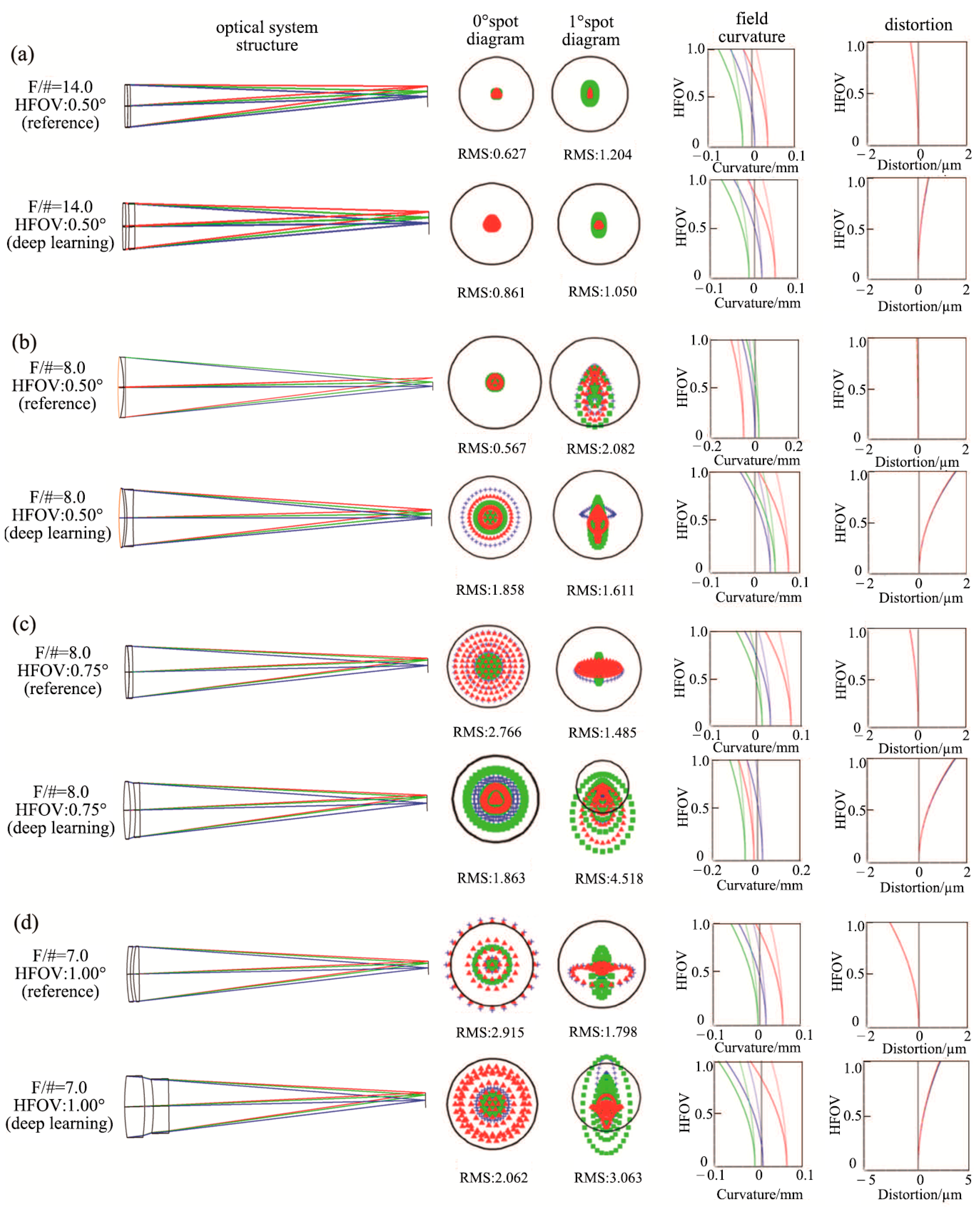
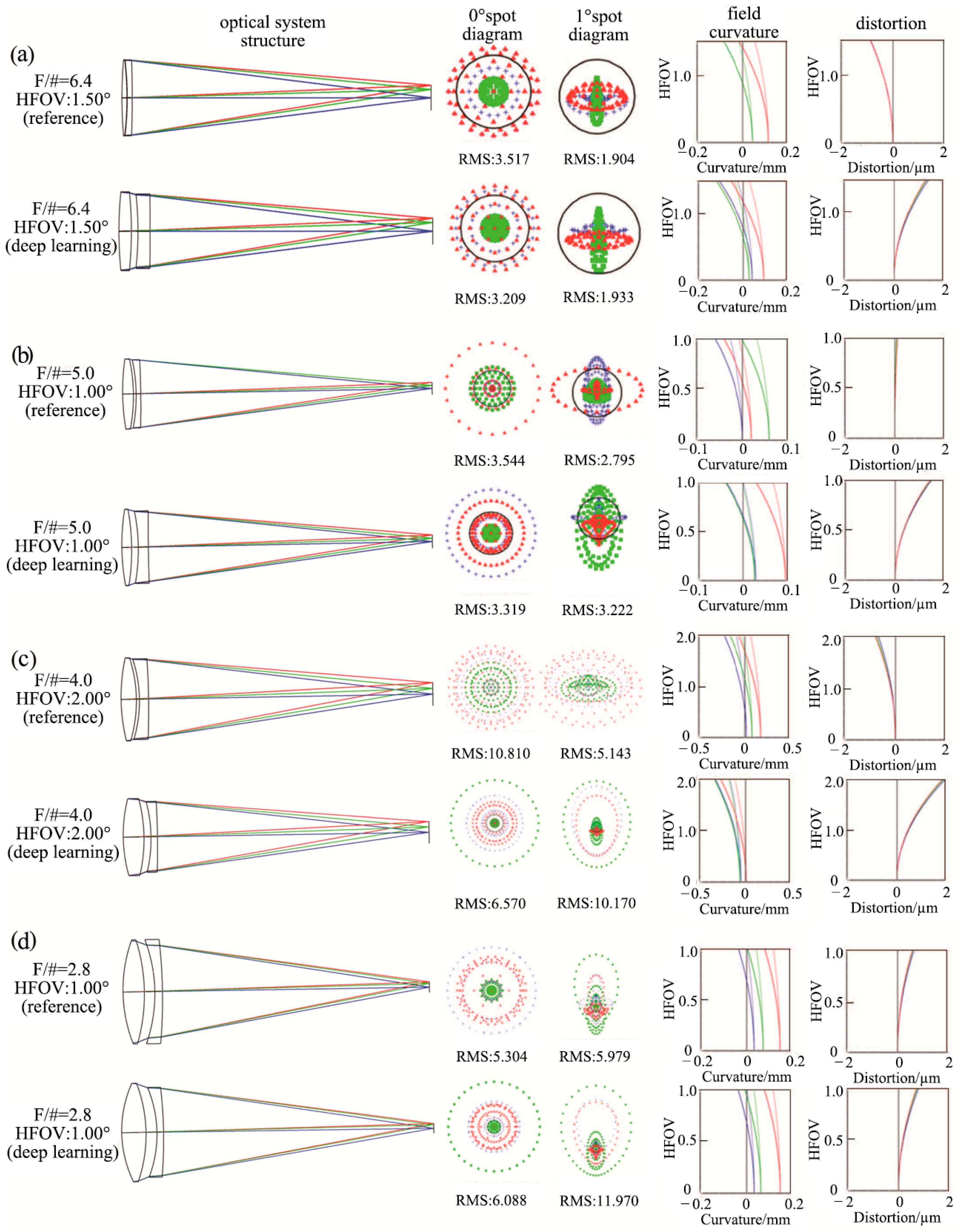
With 2 × 10 5 steps of training, the parameters of the neural network are undergone 2 × 10 5 updates to train a suitable deep-learning model. The trained deep learning network model is completed, and the optical system is designed after the parameters of EPD, FOV, focal length, minimum thickness, and thickness range are given. To facilitate comparison, the focal length of the lens is set to 100 mm, while the focal length of the reference lens with the same EPD and FOV is scaled to 100 mm. The specific comparison is shown in Figure 2 and Figure 3. The optical structure diagram, point sequence diagram, field curvature diagram, and distortion diagram of the lens designed by deep learning and the reference lens with the same EPD and FOV are compared, respectively. Upon comparison, it can be seen that the RMS spot radius of the lens designed by deep learning is close to that of the reference lens and even smaller than that of some deep learning lenses. It is shown that the network model can design the initial structure of the refractive optical system, which can meet the requirements of actual imaging quality.
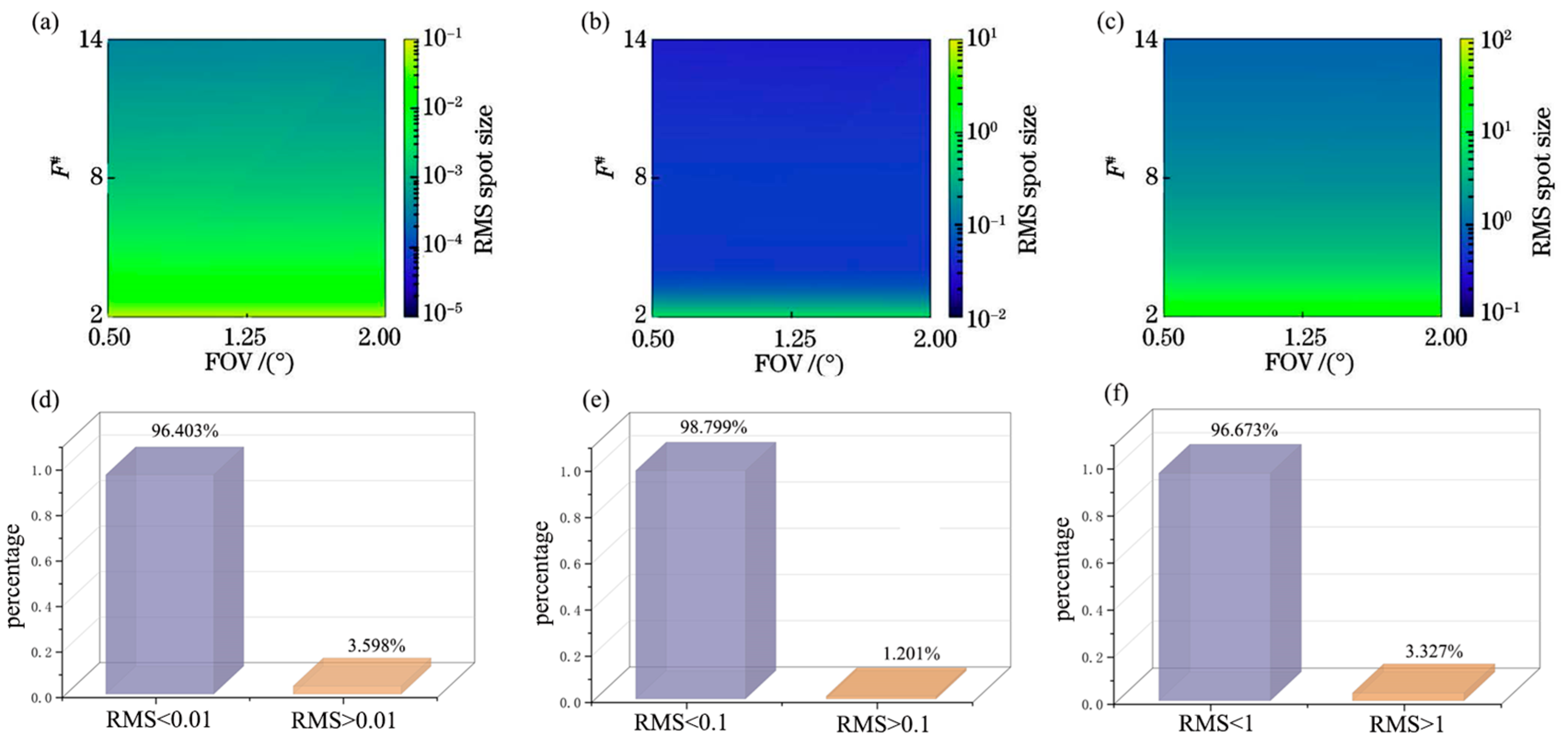
In addition to verifying the optical performance of the deep learning network model designed and the reference optical system with the same EPD and FOV, it is also necessary to verify the generalization ability of the initial structure of the optical system under different focal lengths. Figure 4a, Figure 4b, and Figure 4c show the corresponding RMS spot size when the focal length is set to 1 mm, 100 mm, and 1000 mm, respectively. Aperture is calculated by focal length and F-number, so F-number is used to represent EPD, and F-number generates 1000 sets of data on average within the range. Similarly, the field of view generates 1000 sets of data on average within the range, and the output of optical systems with different EPD and FOV is 1 million sets. The radius of initial structures generated under different EPD and FOV are represented using the heat map. It can be seen from Figure 4a–c that under different focal lengths, the network model can generate not only the optical system equivalent to the reference lens but also the corresponding optical system under different EPD and FOV. The spot radius decreases with an increase in the F number; in other words, with the same focal length, the spot radius decreases as the EPD decreases. Figure 4d, Figure 4e, and Figure 4f show the proportion of the optical system generated by the model that meets the design requirements under focal lengths of 1 mm, 100 mm, and 1000 mm, respectively. Taking Figure 4d as an example, when the RMS spot radius of the optical system generated at focal length 1 is less than 0.01 mm, the designed optical system meets the requirements and is regarded as a successful design. As can be seen from the pie chart, the success rate of the network design optical system is 96.403%. Similarly, when the focal length is 100, the success rate of the network design optical system is 98.799%; when the focal length is 1000, the success rate of the network design optical system is 96.673%. It shows that the network model has good generalization ability and the designed optical system meets the requirements.
The above experiments make the network training stable by adjusting the hyperparameters, such as the learning rate. The network model trained by deep learning can design an optical system comparable to the reference lens through a limited reference lens. At the same time, the network can generate more initial structures of optical systems in proper EPD and FOV, which have certain generalization abilities.

3.2. Tolerance Analysis of Optical Systems

In addition to comparing the aberrations in the optical system and judging the design success rate and generalization ability, it is also necessary to conduct corresponding tolerance analysis and comparison to judge whether the optical system designed by deep learning meets the actual application standards in terms of tolerance. This study sets a certain tolerance range for tolerance analysis. The modulation transfer function (MTF) of the system designed by deep learning under different probabilities is compared with the MTF of the reference lens. The specific comparison is shown in the following table.
The tolerances of eight groups of different apertures and fields of view are analyzed, respectively, in Table 3. Monte Carlo sampling calculation is used to obtain these data. The specific tolerance range of the optical system in the tolerance analysis is set in Table 4 and Table 5 below.
Through the comparison of data in Table 3, it is found that after tolerance analysis, the MTF gap between the optical system designed by deep learning and the reference lens designed by traditional methods is not large under different probabilities, and the MTF of the optical system designed by deep learning under some aperture and field of view has a 90% probability greater than 0.2, meeting the actual application requirements. Therefore, the polarization optical system design method based on deep learning proposed in this study can meet the practical application requirements in terms of tolerance.

3.3. Polarization Aberration Verification

  • Polarization degree change
The change in polarization degree reflects the influence of the optical system on the polarization state of polarized light. In this study, the polarization aberration of the polarization optical system designed by deep learning and the reference lens will be compared. The incident polarized light will be set as linearly polarized light. The difference calculation is carried out to compare the improvement of polarization change between the deep learning design system and the reference lens. It is impossible to accurately compare the percentage increase between the polarization degree change in the system designed by deep learning and the reference lens only upon comparing the data graph. Therefore, specific data are calculated using the following formula:
P c = P r P d P r
where P r is the polarization change in the reference lens, P d is the system polarization change designed for the deep learning field.
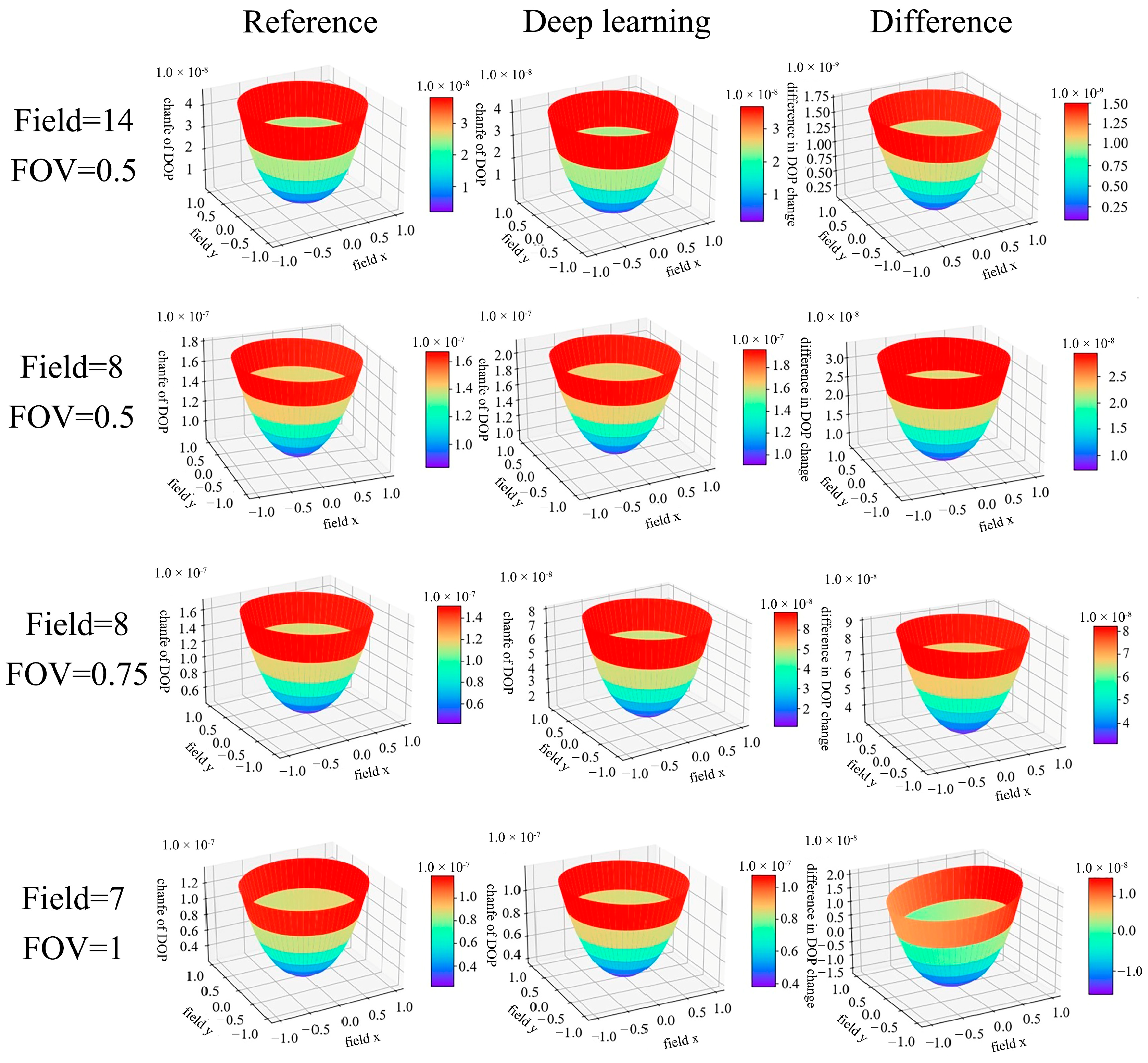
Through ray tracing calculation, the comparison results of polarization change in eight groups of deep learning design lenses and reference lenses are drawn, respectively, as shown in Figure 5 and Figure 6.
To more intuitively compare the percentage increase in this variable between the deep learning design system and the reference lens under the combination of different aperture fields of view, the percentage increase in polarization degree change in different aperture fields of view is summarized in a table, as shown in Table 6:
Through comparison, it is found that the polarization degree change in optical systems designed by deep learning is improved; that is, the influence of the system designed by deep learning on the polarization degree of polarized light is reduced. Due to the different aperture and field of view combinations of the eight lens groups, through the comparison of different F numbers, the system with the same field of view found that when the F-number of the system was large, the polarization degree change in the optical system designed by deep learning was less than that of the reference lens. Upon comparing the systems with the same F number under different fields of view, it is found that when the field of view of the system is larger, the polarization change in the optical system designed by deep learning is less than that of the reference lens.
2.
Stokes vector contrast
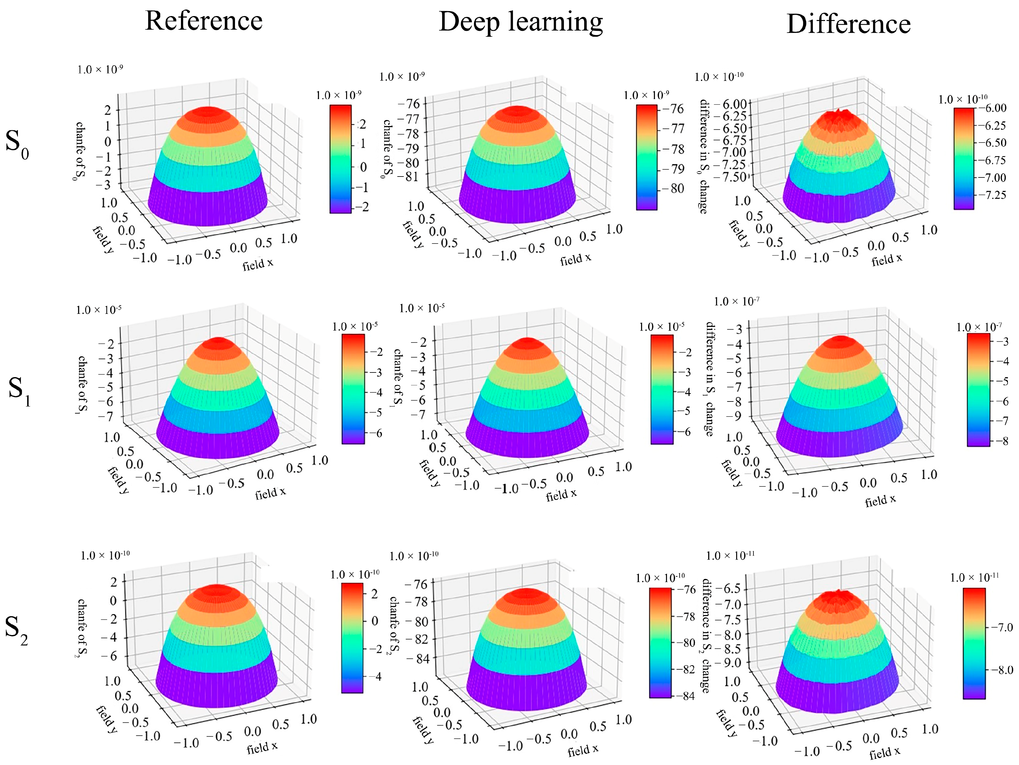
The first two sections compare the image quality of the optical system designed by deep learning and the improvement in the degree of polarization change, indicating that the influence of the optical system designed by deep learning on the polarization degree of polarized light is reduced under the premise of good image quality. This section compares the Stokes vector parameter changes between the optical system designed by deep learning and the reference lens. The influence of the optical system and the reference lens designed by deep learning on polarized light is judged by the variation in the Stokes vector.
For the convenience of comparison, the calculation method of polarization degree change contrast is adopted. The specific formula is as follows:
S c = S r S d S r
In this equation, the Stokes vector parameter change amount after the reference lens S d is the Stokes vector parameter change amount after the optical system designed by deep learning.
Take the optical system designed when the F-number is 4, and the field of view is 0.5° as an example. Upon comparing the changes in the parameters of the polarized Stokes vector, Figure 7 shows the total light intensity between the optical system designed by deep learning and the Stokes vector of the polarized light in the reference lens when the F-number is 14, and the field of view is 0.5°. Compared with the reference lens, the change amount in the optical system designed by deep learning through the difference calculation was increased by 0.00912%, and the change amount in the optical system designed by deep learning was increased by 1.67%. The change amount in the optical system designed by deep learning was increased by 0.00913% compared with that of the reference lens.
To more intuitively compare the percentage increase in this variable between the deep learning design system and the reference lens, the percentage increase in Stokes vector parameter change is summarized in the Table 7:
Through the comparison of Stokes vector parameters S 0 , S 1 , S 2 between the optical system designed by deep learning and the reference lens above, it can be seen that the optical system designed by deep learning and the reference lens have little change in the total light intensity S 0 and the intensity difference S 2 of polarized light in the direction of 45° and 135°. This is because the linear polarized light of 0° or 90° is used as the incident light of the system in this study. Therefore, it has little influence in the directions of 45° and 135°. Upon comparing the intensity difference S 1 of polarized light in the horizontal direction and the vertical direction, it is found that the polarized light does have a relatively large change in the intensity difference between the horizontal direction and the vertical direction.

4. Conclusions

In this study, we propose a method to optimize the initial structure design of a polarized optical system by using deep learning. Samples are trained by combining supervised training and unsupervised training. Supervised training helps the deep neural network model learn the structural features of the optical system. Through experimental simulation, under different focal lengths, the network model can generate 1 million sets of the initial structure of the optical system within the specified aperture and field of view, and the design success rate under the specified RMS spot radius is better than 96.403%, indicating that the network model has certain generalization ability after deep learning. The resulting system polarization change is 4.166% more than that of the reference lens, indicating that the designed system has less influence on the polarization, and the polarization effect is effectively controlled. The deep learning optical design method proposed in this study provides a new solution for future complex optical systems and an effective way to improve the design accuracy of special optical systems such as polarization optical systems. It can be used to optimize the design of high-precision optical systems such as space target detection, multi-dimensional optical remote sensing, high-precision polarization release navigation, photoresist objective lens, etc., which provides a theoretical basis for the design of a new generation of intelligent optical systems.
When using deep learning to optimize the design of optical systems, the spot size and polarization of the optical system are used as the evaluation criteria for the optimization design, which controls the optimization direction of the optical system to a certain extent. Still, the actual design of the optical system optical aberration needs to take into account spherical aberration, coma aberration, image dispersion, field curvature, aberrations, chromatic aberration, and so on. Polarization aberration needs to be considered as the phase delay, attenuation, and so on. In the future, more evaluation criteria can be added to improve the optimal design of neural networks for specific systems. This study only focuses on the optimal design of simple optical systems and can only learn for a specific number of lenses, and the subsequent introduction of new network models, such as recurrent neural networks that can be trained according to the time series, will help the optimal design of optical systems with different numbers of lenses under the same aperture and field of view parameters.

Author Contributions

Conceptualization, H.S. (Haodong Shi); methodology, C.H.; resources, J.W., S.Y., M.X., H.S. (Hongyu Sun), Y.L. and Q.F.; writing—original draft preparation, R.F. and C.H. All authors have read and agreed to the published version of the manuscript.

Funding

Natural Science Foundation of Jilin Province (YDZJ202301ZYTS417).

Institutional Review Board Statement

Not applicable.

Informed Consent Statement

Not applicable.

Data Availability Statement

The raw data supporting the conclusions of this article will be made available by the authors without undue reservation.

Acknowledgments

The authors would like to thank the editors and reviewers for their efforts in supporting the publication of this study.

Conflicts of Interest

The authors declare no conflicts of interest.

References

  1. Smith, W.J. Modern Lens Design; McGraw Hill Professional: New York, NY, USA, 2004. [Google Scholar]
  2. Meiron, J. Damped Least-Squares Method for Automatic Lens Design. J. Opt. Soc. Am. 1965, 55, 1105–1109. [Google Scholar] [CrossRef]
  3. Sun, J.F.; Li, X. Automatic design of machine vision lens based on improved genetic algorithm and damped least squares. In Proceedings of the Optical Design and Testing XI, Nantong, China, 10–12 October 2021; COS Photonics Asia. Volume 11895, pp. 188–202. [Google Scholar]
  4. Glatzel, E.; Wilson, R. Adaptive automatic correction in optical design. Appl. Opt. 1968, 7, 265–276. [Google Scholar] [CrossRef] [PubMed]
  5. Forbes, G.W.; Jones, A.E.W. Towards global optimization with adaptive simulated annealing. In Proceedings of the 1990 International Lens Design Conference, Monterey, CA, USA, 1 January 1990; SPIE Optical Systems Design. Volume 1354, pp. 144–153. [Google Scholar]
  6. Höschel, K.; Lakshminarayanan, V. Genetic algorithms for lens design: A review. J. Opt. Soc. 2018, 48, 463–470. [Google Scholar] [CrossRef]
  7. Isshiki, M.; Ono, H.; Hiraga, K.; Ishikawa, J.; Nakadate, S. Lens Design: Global Optimization with Escape Function. Opt. Rev. 1995, 2, 463–470. [Google Scholar] [CrossRef]
  8. Menke, C. Application of particle swarm optimization to the automatic design of optical systems. In Proceedings of the Optical Design and Engineering VII, Frankfurt, Germany, 14–17 May 2018; SPIE Optical Systems Design. Volume 10690, pp. 1–10. [Google Scholar]
  9. Yang, T.; Jin, G.-F.; Zhu, J. Automated design of freeform imaging systems. Light Sci. Appl. 2017, 6, 17081. [Google Scholar] [CrossRef] [PubMed]
  10. Yang, T.; Cheng, D.; Wang, Y. Direct generation of starting points for freeform off-axis three-mirror imaging system design using neural network based deep-learning. Opt. Express 2019, 27, 17228. [Google Scholar] [CrossRef] [PubMed]
  11. Gannon, C.; Liang, R. Using machine learning to create high-efficiency freeform illumination design tools. arXiv 2019, arXiv:1903.11166. [Google Scholar]
  12. Côté, G.; Lalonde, J.-F.; Thibault, S. Extrapolating from lens design databases using deep learning. Opt. Express 2019, 27, 28279–28292. [Google Scholar] [CrossRef] [PubMed]
  13. Côté, G.; Zhang, Y.; Menke, C.; Lalonde, J.-F.; Thibault, S. Inferring the solution space of microscope objective lenses using deep learning. Opt. Express 2022, 30, 6531–6545. [Google Scholar] [CrossRef] [PubMed]
  14. Anche, R.M.; Sen, A.K.; Anupama, G.C.; Sankarasubramanian, K.; Skidmore, W. Analysis of polarization introduced due to the telescope optics of the Thirty Meter Telescope. J. Astron. Telesc. Instrum. Syst. 2018, 4, 018003. [Google Scholar] [CrossRef]
  15. Zhang, Y.; Shi, H.; Jiang, H. Polarization Aberration of a Non-Rotationally Symmetric Optical System with Freeform Surfaces. IEEE Access 2022, 10, 145538–145553. [Google Scholar] [CrossRef]
  16. Berthelot, D. MixMatch: A Holistic Approach to Semi-Supervised Learning. In Proceedings of the Advances in Neural Information Processing Systems 2019, Vancouver, BC, Canada, 8–14 December 2019. [Google Scholar]
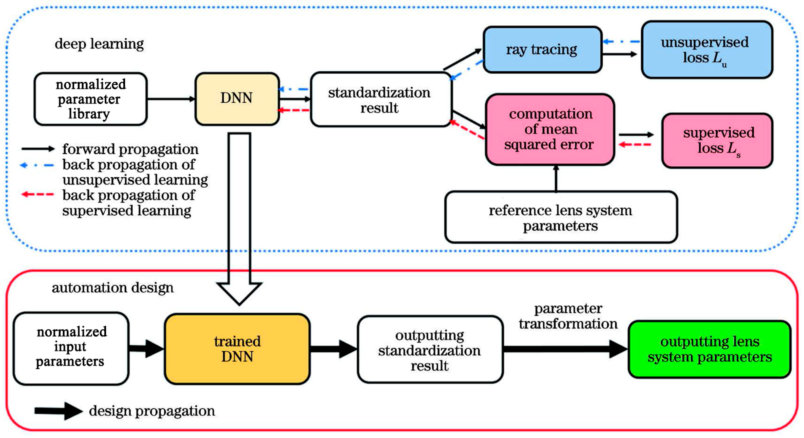
Figure 1. The learning process and design process of deep learning to design polarization optical systems.
Photonics 11 00164 g001
Figure 2. Comparison results of four groups of deep learning design lenses and reference lenses under different apertures while F is 14, 8, and 7. (a) Deep learning design lenses and reference lenses under different apertures while F is 14; (b) Deep learning design lenses and reference lenses under different apertures while F is 8 and HFOV is 0.5°; (c) Deep learning design lenses and reference lenses under different apertures while F is 8 and HFOV is 0.75°; (d) Deep learning design lenses and reference lenses under different apertures while F is 7.
Photonics 11 00164 g002
Figure 3. Comparison results of four groups of deep learning design lenses and reference lenses under different apertures while F is 6.4, 5, 4, and 2.8. (a) Deep learning design lenses and reference lenses under different apertures while F is 6.4; (b) Deep learning design lenses and reference lenses under different apertures while F is 5; (c) Deep learning design lenses and reference lenses under different apertures while F is 4; (d) Deep learning design lenses and reference lenses under different apertures while F is 2.8.
Photonics 11 00164 g003
Figure 4. Network model generalization ability test results. (ac) Spot radius heat map of an optical system with different apertures and fields of view at different focal lengths; (df) Success ratio of optical system design with different apertures and fields of view at different focal lengths.
Photonics 11 00164 g004
Figure 5. Comparison results of four groups of polarization change deep learning design lenses polarization change and reference lenses under different apertures while Field is 14, 8, and 7 and FOV is 1, 0.75, and 0.5.
Photonics 11 00164 g005
Figure 6. Comparison results of four groups of polarization change deep learning design lenses and reference lenses under different apertures while Field is 6.4, 5, 4, and 2.8 and FOV is 2, 1.5, and 1.
Photonics 11 00164 g006
Figure 7. Comparison results of Stokes vector of deep learning design lenses and reference lenses under different apertures while Stokes is S 0 , S 1 , and S 2 .
Photonics 11 00164 g007
Table 1. Network structure and application of different networks.
NetworkNetwork StructureApply
DNNInput layer, hidden layer, active layer, output layerComplex nonlinear fitting, complex classification problems, simple image recognition
CNNConvolution layer, pooling layer, fully connected layerImage recognition, image classification, image segmentation, speech recognition
RNNInput layer, hidden layer, output layer, hidden stateSpeech recognition, machine translation, text and music generation
Table 2. Error comparison between the actual optical path calculation and the algorithm written in this study.
Contrast ParameterOptical Path Calculation of Actual Optical SystemThis Study Compiled the Algorithm CalculationError Value
Paraxial ray image distance97.00997.00920.0002
Paraxial image square aperture Angle0.1001040.10020.000096
Second paraxial ray ideal image height distance5.228165.22820.0004
Off-axis point meridian plane main ray distance0.80520.80520
Off-axis point image square aperture Angle−0.052−0.05230.0003
Table 3. MTF of the optical system and reference lens is designed by deep learning under different probabilities calculated by Monte Carlo sampling.
Optical SystemProbabilityMTF for Deep Learning SystemsReference Lens MTFThe Absolute Value of the Difference
F = 14
HFOV = 0.5
90%0.66570.65520.0105
50%0.67800.67770.0003
10%0.68620.68760.0014
F = 8
HFOV = 0.5
90%0.30470.25400.0506
50%0.46960.41860.0509
10%0.68670.63240.0543
F = 8
HFOV = 0.75
90%0.55960.71140.1517
50%0.69170.765450.0737
10%0.75850.797430.0388
F = 7
HFOV = 1
90%0.54840.69830.1499
50%0.67670.78410.1074
10%0.79290.81870.0258
F = 6.4
HFOV = 1.5
90%0.62450.61160.0129
50%0.71590.71200.0038
10%0.77020.79020.0199
F = 5
HFOV = 1
90%0.41970.39610.0236
50%0.60820.59330.0149
10%0.74730.76180.0144
F = 4
HFOV = 2
90%0.23040.21780.0126
50%0.33510.33490.0002
10%0.43860.40840.0302
F = 2.8
HFOV = 1
90%0.21080.20150.0093
50%0.30640.35080.0444
10%0.47970.49940.0197
Table 4. The surface tolerance range of the optical system.
TypeValue
Radius of curvature (fringe)1
Surface irregularity (fringe)0.2
Thickness (mm)0.1
Surface tilt (degree)0.1
Refractive index0.001
Abbe number0.1
Table 5. The component tolerance range of the optical system.
TypeValue
Thickness (mm)0.1
Surface eccentricity (mm)0.02
Surface tilt (degree)0.1
Table 6. Under the combination of eight groups of aperture field of view, the deep learning design optical system and the reference lens polarization degree change increased by a percentage.
F = 14
HFOV = 0.5
F = 8
HFOV = 0.5
F = 8
HFOV = 0.75
F = 7
HFOV = 1
F = 6.4
HFOV = 1.5
F = 5
HFOV = 1
F = 4
HFOV = 2
F = 2.8
HFOV = 1
4.753%12.349%10.071%10.001%4.166%15.625%23.45%23.75%
Table 7. When F is 14, and the field of view is 0.5°, the polarization change in data in the deep learning-designed optical system and the reference lens will increase by a percentage.
S 0 S 1 S 2
0.00912%1.67%0.00913%
Disclaimer/Publisher’s Note: The statements, opinions and data contained in all publications are solely those of the individual author(s) and contributor(s) and not of MDPI and/or the editor(s). MDPI and/or the editor(s) disclaim responsibility for any injury to people or property resulting from any ideas, methods, instructions or products referred to in the content.