Article

A New Method for Indoor Visible Light Imaging and Positioning Based on Single Light Source

1
Faculty of Automation and Information Engineering, Xi’an University of Technology, Xi’an 710048, China
2
Shaanxi Civil-Military Integration Key Laboratory of Intelligence Collaborative Networks, Xi’an 710126, China
*
Author to whom correspondence should be addressed.
Photonics 2024, 11(12), 1199; https://doi.org/10.3390/photonics11121199
Submission received: 25 November 2024 / Revised: 15 December 2024 / Accepted: 18 December 2024 / Published: 20 December 2024

Abstract

:
Visible light positioning (VLP) can provide indoor positioning functions under LED lighting, and it is becoming a cost-effective indoor positioning solution. However, the actual application of VLP is limited by the fact that most positioning requires at least two or more LEDs. Therefore, this paper introduces a positioning system based on a single LED lamp, using an image sensor as the receiver. Additionally, due to the high computational cost of image processing affecting system real-time performance, this paper proposes a virtual grid segmentation scheme combined with the Sobel operator to quickly search for the region of interest (ROI) in a lightweight image processing method. The LED position in the image is quickly determined. Finally, the position is achieved by utilizing the geometric features of the LED image. An experimental setup was established in a space of 80 cm × 80 cm × 180 cm to test the system performance and analyze the positioning accuracy of the receiver in horizontal and tilted conditions. The results show that the positioning accuracy of the method can reach the centimeter level. Furthermore, the proposed lightweight image processing algorithm reduces the average positioning time to 53.54 ms.

1. Introduction

With the development of the economy and technology, as well as the rise of large shopping malls and comprehensive venues, people’s demand for indoor navigation and positioning is increasing. Because satellite signals are blocked by buildings, GPS cannot be used directly in indoor environments [1]. Traditional indoor positioning methods, such as Bluetooth, Wi-Fi, radio frequency identification and ultra-wideband, have problems such as large positioning errors, a vulnerability to multipath effects and electromagnetic interference, and difficulty in providing reliable positioning services [2,3]. The rapid development of visible light communication technology provides an alternative for indoor positioning systems, namely Visible Light Positioning (VLP). VLP systems are low cost, possess anti-electromagnetic interference, and have low power consumption, usually consisting of light-emitting diodes (LEDs) as transmitters, photodiodes (PD), or image sensors (IS) as receivers [4,5]. The PD-based non-imaging positioning technology is positioned by receiving the light intensity of different LEDs and is susceptible to background light interference. In contrast, IS-based imaging positioning technology uses the LED projection on the image as the foreground, reducing ambient light interference through image processing and improving positioning accuracy. In addition, due to its insensitivity to the direction of light, the latter positioning system is more suitable for locating moving objects in indoor environments [6]. With the wide application of a complementary Metal Oxide Semiconductor (CMOS) sensor camera, the imaging positioning system is easier to integrate with current mobile terminals, further enhancing its application prospect [6,7,8].
However, in these IS-based VLP systems, the positioning scheme of multiple LEDs IS limited by many factors such as the camera field of view and LED layout, resulting in poor robustness and flexibility of the system [9]. In reference [10], the authors propose an indoor positioning algorithm using at least three LEDs, and achieve an accuracy of 0.001 m in simulation. However, when there are fewer than three LEDs in the field of view, the receiver will not be able to locate [10]. The document [11] used two LED lamps and a camera as receivers to achieve a positioning accuracy of several centimeters in a 3-D system, but positioning failed when only one LED was captured [11]. In the case of sparse spatial light sources, such as long corridors or tunnels, LEDs are usually arranged with longer spacing [12,13]. Therefore, in order to solve the problem of single-LED positioning, an unbalanced single-LED VLP algorithm was proposed in the literature [14], which requires additional beacon search for the light source projection. This approach requires placing additional markers on the LED lights, increasing computational complexity and system cost [14]. The literature [8] proposes a VLP positioning method based on proximity; that is, the receiver location is set as the location of the nearest detected luminaire. Although this solution reduces system complexity, its accuracy depends on the density of the lighting device [8].
The VLP system based on IS is divided into a single LED and multi-LED positioning system according to the number of LEDs. In Ref. [9], the author proposed an indoor positioning algorithm that uses at least three LEDs and achieved a precision of 0.001 m in simulation. However, when fewer than three LEDs are visible in the field of view, the receiver will not be able to locate [9]. Ref. [10] uses two LED light fixtures and a camera as the receiver to achieve sub-centimeter positioning accuracy in a three-dimensional system but fails to locate when only one LED is captured [10]. This is because the multi-LED positioning scheme is highly dependent on factors such as the camera field of view and LED layout, leading to poor robustness and flexibility of the system [11]. Compared to the high dependence of the multi-LED system on multiple LED layout and camera field of view, the single-LED system avoids these limitations and can achieve stable positioning by relying on a single LED light source. This not only reduces hardware requirements and system complexity, but also improves robustness and flexibility, making it more suitable for scenarios with fewer LEDs or where it is not guaranteed that multiple LEDs can be captured simultaneously. For example, in sparse lighting scenarios such as long corridors or tunnels, LEDs are typically spaced at longer intervals, and the advantages of the single-LED system are particularly prominent [12,13]. However, Ref. [14] proposed an unbalanced single-LED VLP algorithm that requires additional beacon search for the light source projection and requires additional markers to be placed on the LED lamp, increasing the computational complexity and system cost [14]. Ref. [8] proposed a VLP positioning method based on proximity, where the receiver position is set to the nearest detected lamp position. This solution reduces system complexity, but its accuracy depends on the density of the lighting devices [8]. Therefore, existing methods all have certain limitations and need further exploration. In addition, many studies do not fully consider positioning time, and real-time performance is a key indicator of VLP systems. In general, more than 70% of the time cost in VLP solutions is used for LED feature detection. The literature [15] points out that the computation delay of IS-based VLP systems mainly comes from image processing, especially in the process of extracting the ROI (Region of Interest) of LED light from captured images [15]. Although several high-precision imaging VLP systems have been proposed in the literature [16,17,18,19], the real-time performance of these systems is limited by the high computational delay of image processing, thus affecting their practical applications [16,17,18,19].
Therefore, a visible light positioning system based on a single LED and image sensor is proposed in this paper. The system achieves positioning based on the geometric features presented by the LED in the captured image, simplifying the system structure and providing centimeter-level positioning accuracy. In addition, this paper proposes a virtual grid segmentation scheme combined with a Sobel operator to quickly search the ROI region algorithm. This detection and recognition algorithm does not need to traverse all pixels, and can quickly locate the LED position on the image with low complexity, thus improving the real-time performance of the system.

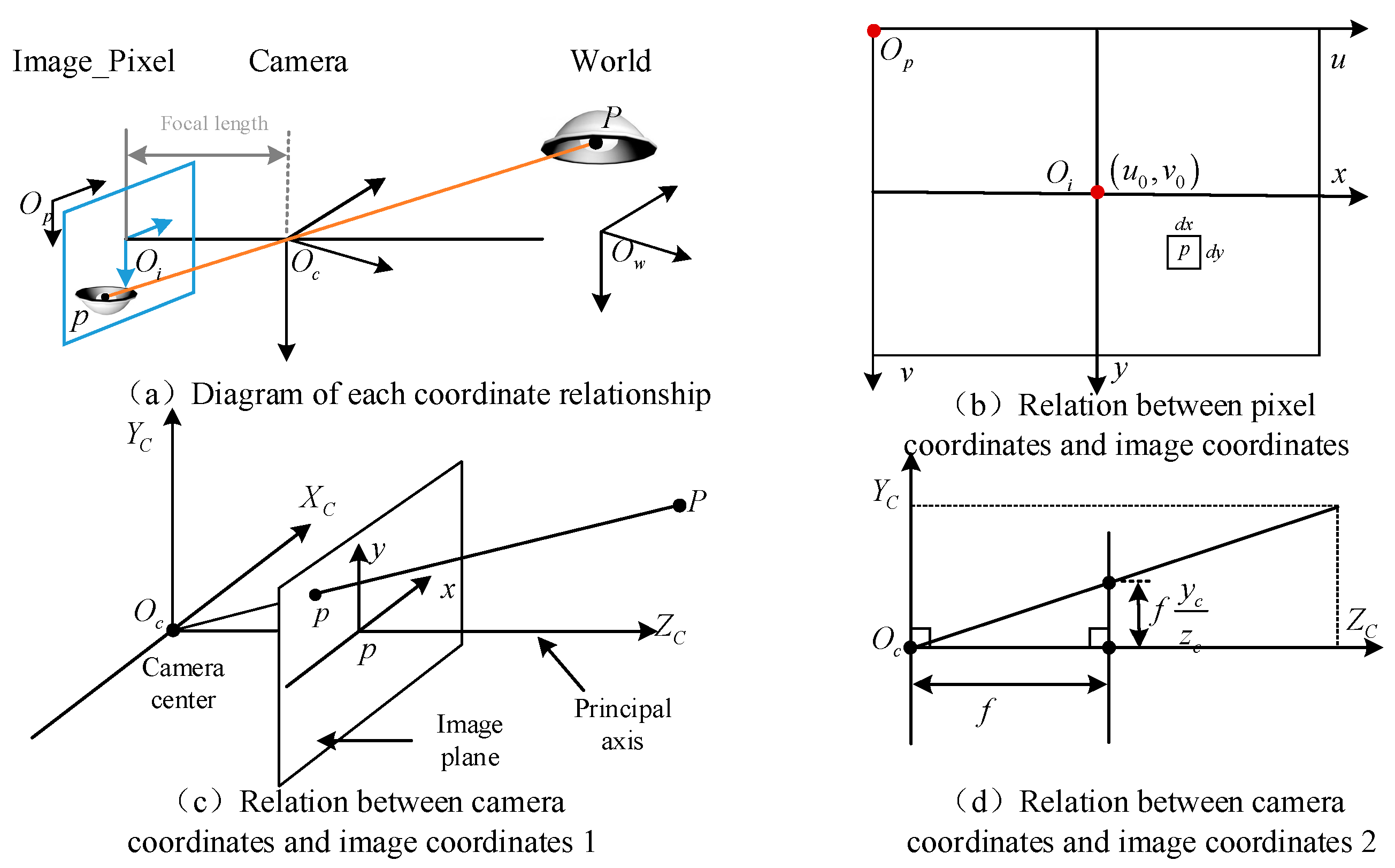
2. Positioning Principle

The system proposed in this paper uses IS as a receiver, and an imaging model can be used to describe the imaging process of IS under ideal conditions [20]. From this, we can determine the position of a point on an LED in the three-dimensional world on a two-dimensional image [7,20]. In the imaging model, four coordinate systems are mainly involved: the world coordinate system, camera coordinate system, image coordinate system and pixel coordinate system, and the transformation relationship between them is shown in Figure 1.
The world coordinate system O W X w Y w Z w is a three-dimensional coordinate system that exists in physical space and can be arbitrarily specified with three axes and origin, generally in mm. The camera coordinate system O C X c Y c Z c is the reference coordinate system of the IS itself; the origin is located in the optical center of the lens, the Z c axes coincide with the optical axis, the X c and Y c axes are parallel to the horizontal plane of the image, and the unit is generally mm. The image coordinate system O i x y is a two-dimensional coordinate obtained after imaging through the aperture. The origin is the intersection of the optical axis and the imaging plane. Axis x and y are parallel to axis X c and Y c , respectively, in mm. The pixel coordinate system O p u v is a two-dimensional coordinate system representing the position of a point on an image, with the origin located in the upper left corner of the image; the unit is pixel.
The conversion between coordinate systems can be divided into three steps:
In the first step, the world coordinate of any point P on the LED is assumed to be P W x w , y w , z w , and the point P C x c , y c , z c in the camera coordinate system is obtained by rigid body transformation.
In the second step, in the imaging system, a point in space is imaged on the image plane and the distance from the origin is f. A cross-section of Z C O Y C is taken, as shown in Figure 1d. According to the similar triangle relationship, the imaging point of point P C x c , y c , z c in the image coordinate system is p ( x , y ) .
In the third step, since the origin of the image coordinate system is in the center of the sensor, the unit is mm, which is a physical unit, the origin of the Pixel coordinate system is in the upper left corner of the sensor, and the unit is pixel. According to the transformation relationship, the point of the pixel coordinate system corresponding to p x , y in the image coordinate system is p u , v .
To summarize the whole process, as shown in Figure 2, the relationship between the world coordinates of any point on the LED and its pixel coordinates can be obtained as follows:
z c u v 1 = 1 d x 0 u 0 0 1 d y v 0 0 0 1 f 0 0 0 0 f 0 0 0 0 1 0 R 3 × 3 T 3 × 3 0 0 x w y w z w 1 = M 1 M 2 x w y w z w 1
where, d x d y is the inherent parameter of the camera, and d x represents the width of a pixel in mm (x direction), in mm/pixel; u 0 v 0 : represents the offset of the origin of the image coordinate system to the origin of the pixel coordinate; R is the rotation matrix of the camera coordinate system with respect to the world coordinate system and T is the translation matrix of the camera coordinate system with respect to the world coordinate system.
The rotation matrix R and the translation matrix T in Equation (1) are, respectively,
R = R x α R y β R z γ = 1 0 0 0 cos α sin α 0 sin α cos α cos β 0 sin β 0 1 0 sin β 0 cos β cos γ sin γ 0 sin γ cos γ 0 0 0 1
T = t x t y t z
In Equation (2), α , β and γ are the radians of the IS rotation around the X c , Y c and Z c axes, respectively.
In Equation (3), the elements of the matrix represent the offsets of the IS from the axes of the world coordinate system and is the opposite number according to the imaging characteristics.
However, the applicability of imaging models in complex environments still has some limitations. In the environment of strong reflection, it is easy to cause changes in the optical path, which makes the edge of the light source blurred, and it is difficult to distinguish the true position of the light source in the imaging plane; that is, it affects the accuracy of the pixel coordinates. In addition, when the line of sight of the LED light source or the receiver is blocked by an object, the receiver cannot receive a complete signal. This occlusion effect may lead to some LED light sources not being captured, and the acquisition of imaging information being incomplete. Therefore, the above complex environment, as well as the ambient light background light environment, may cause errors in the imaging model.

3. Positioning Method

3.1. System Architecture

The architecture of the visible light positioning system constructed in this paper is shown in Figure 3. At the LED transmitting end, a Field-Programmable Gate Array (FPGA) board is used to modulate the LEDs and assign them characteristic information, and the information is associated with the world coordinate of the LED through a database. The LED driver controls its on/off state to make the visible light emitted by it contain the signal of the characteristic information [7].
At the receiving end, an image of the LED is captured by a camera equipped with a CMOS image sensor. Due to the rolling shutter mechanism of the CMOS sensor, the image of the LED light source captured will have bright and dark stripes, with bright stripes representing “1” and dark stripes representing “0”. The characteristic information sent by the LED light source can be decoded by analyzing the stripe code. By querying the database, the position of the LED in the world coordinate system can be determined [21]. Combining the shape information of the LED lamp and the positioning algorithm, it is finally possible to achieve visible light positioning [22].
The transmitter and receiver of the above system architecture are further analyzed. In view of the fact that downlights emit uniform light without a blooming effect and are mainstream indoor lighting fixtures, this system uses downlights as emitters, adopts Pulse Width Modulation-On Off Keying (PWM-OOK), and introduces frequency and duty cycle as LED characteristic information [23]. Among them, the modulation frequency needs to be higher than the LED flicker frequency that the human eye cannot perceive and is limited by the image sensor line scan frequency to avoid data loss. This modulation method is easy to decode at the receiving end and does not need to consider synchronization [24]. In addition, the Lighting Research Center shows that when the luminaire’s flicker rate exceeds 1 kHz, the occupants usually cannot perceive the flicker or bloom effect, which does not affect daily life [25].

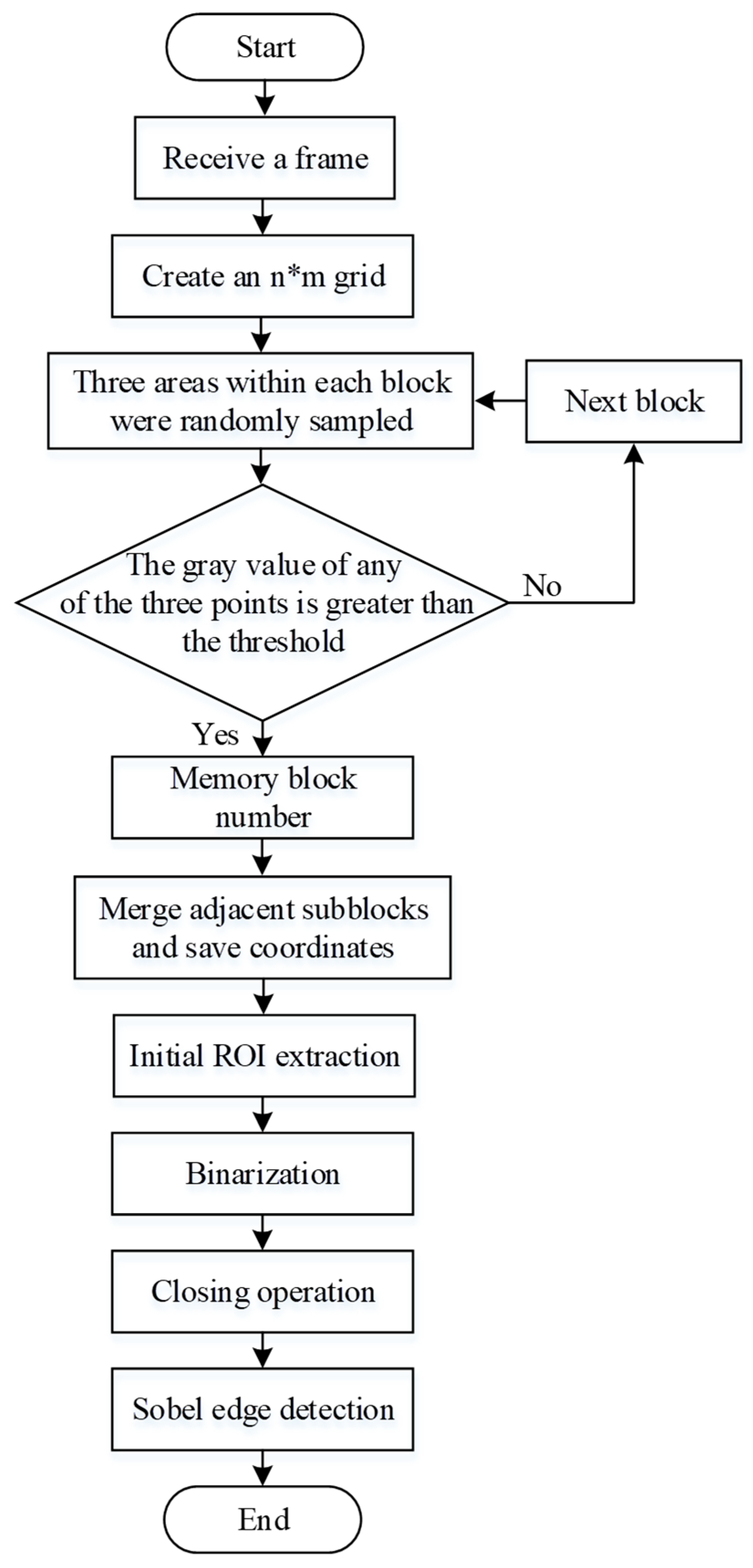
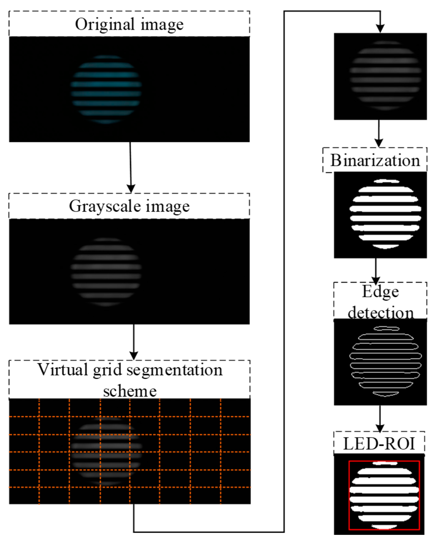
3.2. LED Image Recognition and Detection

A VLP system mainly includes LED image recognition and detection, and a positioning algorithm with two major links. In the process of LED image recognition, the first step is to determine the ROI of LED imaging, followed by feature recognition of the area. However, traditional ROI extraction technology is faced with the problem of high computational complexity and lengthy duration. At the same time, ROI extraction in VLP scenarios requires a more accurate delineation of the outline of the LED emitter. Therefore, this paper proposes a fast search strategy that combines virtual grid segmentation with Sobel edge detection. First, the virtual grid segmentation fast search algorithm is used to initially extract the ROI of the LED to achieve rapid positioning of the ROI region [26]. Then, a Sobel operator was used to detect the edge of the initially extracted ROI region to refine the ROI boundary and improve the extraction accuracy.
Figure 4 shows the flow chart of the proposed algorithm. Since the light emitted by the LED is brighter, the pixel gray value of the ROI in the received image is higher than that in the non-interest region. First, the original image is read and converted to a grayscale image. Then, the virtual grid segmentation fast search algorithm is used to extract the grid that may contain the ROI. The specific steps are as follows: First, a virtual grid is established according to the resolution of the captured image, and the image is virtually divided into n × m blocks. After the grid is established, the pixels in the left, middle and right regions of the middle row in each block are sampled to improve the hit rate of ROI detection. The specific method is to randomly select a pixel in the left area of the block. If the gray value of the pixel is higher than the set threshold, the block number is recorded and the next block is processed. If the requirements are not met, the same sampling operation continues in the middle and right areas until all three areas have been checked. After the block number is obtained, the position relationship between the block numbers is determined according to the adjacent criteria to complete the multi-block stitching operation. If the ROI area occupied by the stripes is too small, it may be missed. After determining the coordinate direction of the merged block, it is necessary to expand several pixels around the block to ensure that the position range of the ROI in the image is fully covered and initial extraction is achieved. Then, the obtained grid area is binarized to distinguish the ROI from the background and make the target area more obvious. Then, the closing operation is performed to eliminate small holes and disconnected areas. Finally, the optimized Sobel operator is used for edge detection. The traditional Sobel operator is a pixel gradient-based edge detection algorithm that calculates the gradient in both the horizontal and vertical directions of an image by performing a convolution operation on each pixel point in the image using a 3 × 3 convolution kernel. By calculating the horizontal gradient and vertical gradient of each pixel point, the gradient magnitude and direction of the image at that point can be obtained. Then, the pixels with a larger gradient magnitude are selected as edges, and the edge part of the image is extracted. However, the limitation is that it depends heavily on the pixel point characteristics of the image edge, and its processing ability for edge specifications or blurred images is not high. Therefore, based on the traditional edge detection, the algorithm is optimized by successively processing the row and column ratios and the similarity algorithm of surrounding pixels, removing isolated pixels in the image to highlight the LED feature area and achieve fine-grained ROI positioning. The more accurate LED imaging contour is crucial for improving the positioning accuracy. The image processing flow of this algorithm is shown in Figure 5.
The contour of the fringe is accurately extracted using the Sobel edge detection method, and the pixel count between the transition from a bright line to a dark line is subsequently determined. A single bright line and a single dark line together constitute a complete signal period. Therefore, the modulation frequency can be calculated using the line readout time and the number of vertical pixels in the light and dark lines [27]. Then the duty cycle can be obtained by calculating the ratio between the fringe width of pixel value “1” (bright fringe) and the fringe width of pixel value “0” (dark fringe) [23]. After edge detection, least-square fitting is used to detect the shape information of the LED image to calculate the position of the receiving end [12].

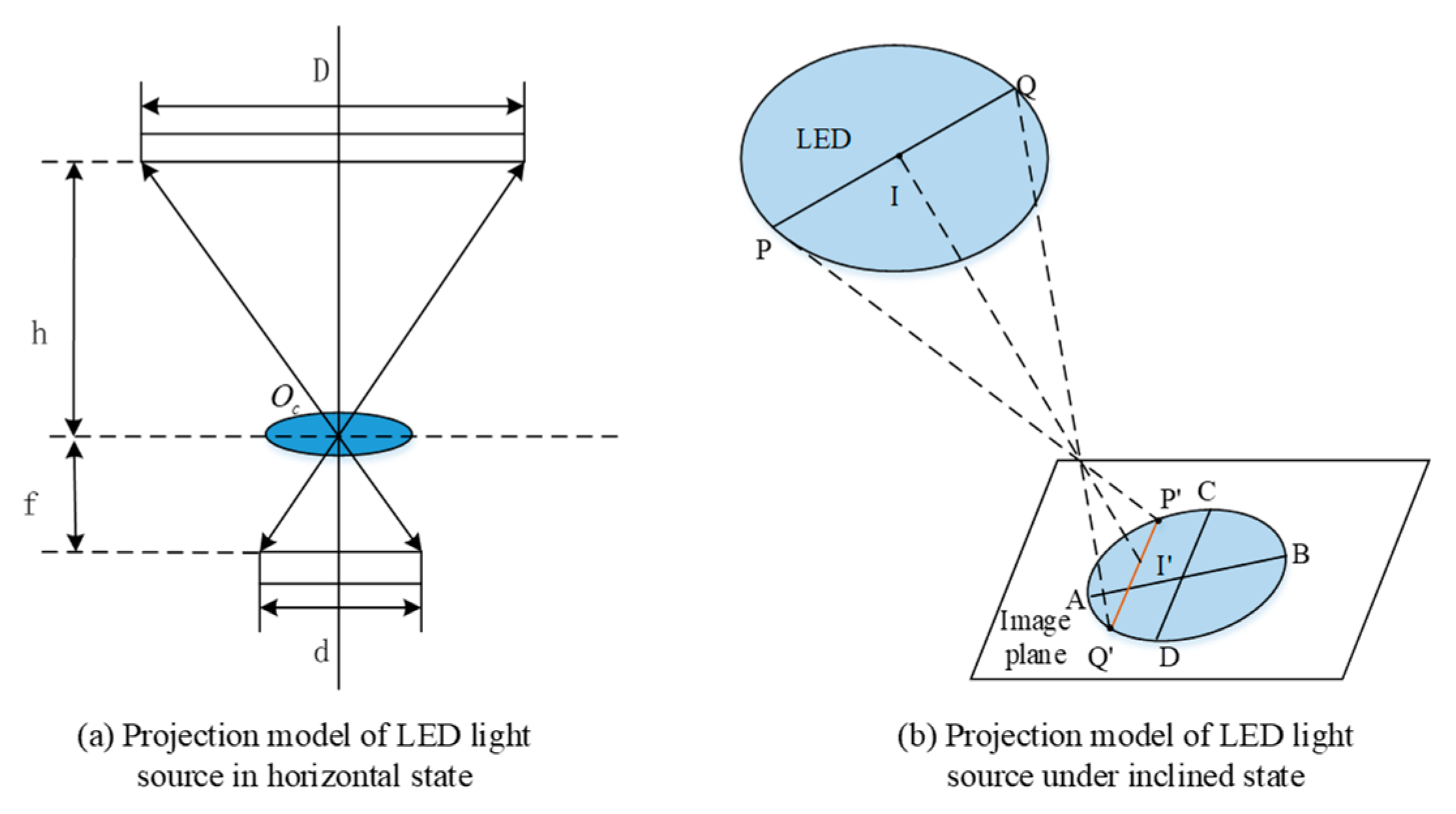
3.3. Positioning Algorithm

Indoor positioning is actually the process of solving the receiving coordinate system. That is, Equation (1) is used to calculate and determine the world coordinates of the receiving end. In theory, there are two states at the receiving end: horizontal and inclined. The corresponding LED projection on the image plane has two possible shapes: circular or oval [8,28,29]. In the image processing in Section 3.2, circular or elliptic equations are obtained by fitting the least square method [12]. So as not to lose generality, let us talk about slant cases. The expression of the elliptic equation obtained by using least square method is as follows:
F x , y = s 1 x 2 + s 2 x y + s 3 y 2 + s 4 x + s 5 y + s 6 = 0
where s = s 1 s 2 s 3 s 4 s 5 s 6 T is the coefficient of the elliptic equation; the six coefficients can be used to calculate the rotation angle of the ellipse w, major axis 2a, minor axis 2b, and center u 0 , v 0 T .
w = 1 2 arctan s 2 s 1 s 3
u 0 , v 0 T = n 1 2 m 1 , n 2 2 m 2 T
2 a = m 2 n 1 2 + m 1 n 2 2 4 m 1 m 2 s 6 4 m 1 2 m 2 , 2 b = m 2 n 1 2 + m 1 n 2 2 4 m 1 m 2 s 6 4 m 1 m 2 2 ,
where,
m 1 = s 1 cos 2   w + s 2 sin w cos w + s 3 sin 2   w
m 2 = s 1 sin 2   w s 2 sin w cos w + s 3 cos 2   w
n 1 = s 4 cos w + s 5 sin w
n 2 = s 4 sin w + s 5 cos w
In the horizontal configuration at the receiving end, as illustrated in Figure 6a, based on the properties of similar triangles, we have the following:
D d = 2 r 2 r = H f
where D is the luminous diameter of the LED lamp, r is the radius, d is the diameter of the circular projection of the LED light source on the pixel plane, r is the radius, f is the focal length, H can be regarded as Z C in Equation (1); that is
Z c = D d × f = 2 r 2 r × f
When the receiving end is tilted, the projection of the LED light source on the imaging plane is an ellipse, as shown in Figure 6b, and there is a deviation between the center projection and the position of the center of mass of the fitted ellipse. In the figure, AB and CD are the long axis and short axis of the elliptic projection, respectively, and P’Q’ is the diameter of the LED light source in the imaging plane. Using the long axis to calculate the height of the receiver leads to high positioning results. The use of a short axis is greatly affected by the tilt angle, and the change is relatively obvious, which introduces more uncertainty. Considering the stability and positioning accuracy, the average value of the major axis and the minor axis of the ellipse is used as the imaging radius.
Z c = D d × f = 2 r 2 r × f
where a and b are the semi-major and semi-minor axes of the elliptic projection of the LED light source on the pixel plane, respectively.
T can be calculated by substituting Z C into Equation (1), and the coordinate transformation between the receiving coordinate system P C and the world coordinate system P W is as follows:
P C = R × P W + T
P W = R 1 × ( P C T )
where P C is the coordinate of the receiving end in the camera coordinate system and P W is the coordinate of the receiving end in the world coordinate system. The world coordinate system of the receiving end can be solved by Equation (12).

4. Experiment and Analysis

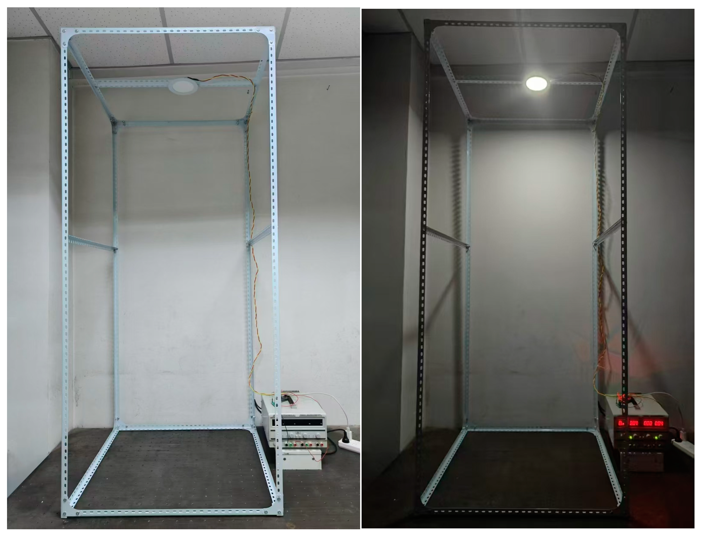
4.1. The Construction of the Experimental System

In order to verify the effectiveness of the algorithm, the experimental platform was built, as shown in Figure 7. The test space size is 80 cm × 80 cm × 180 cm, and the midpoint of the floor plane is defined as the origin of the world coordinate system. At the transmitting end, in the experiment, the PWM OOK modulation signal with frequency set to 2 kHz and duty cycle set to 50% is generated by FPGA, and the LED light is controlled by the current drive circuit. Select a common commercial circular LED lamp tube as the light source, and install the LED light source at a vertical height of 1.8 m from the ground. Using a smartphone as the receiving end, the image sensor adopts a smartphone camera and sets the ISO value to 50, the exposure time to 125 μs, and its camera has 16 megapixels and a resolution of 2046 × 1080 pixels. The key parameters of the experiment are shown in Table 1.

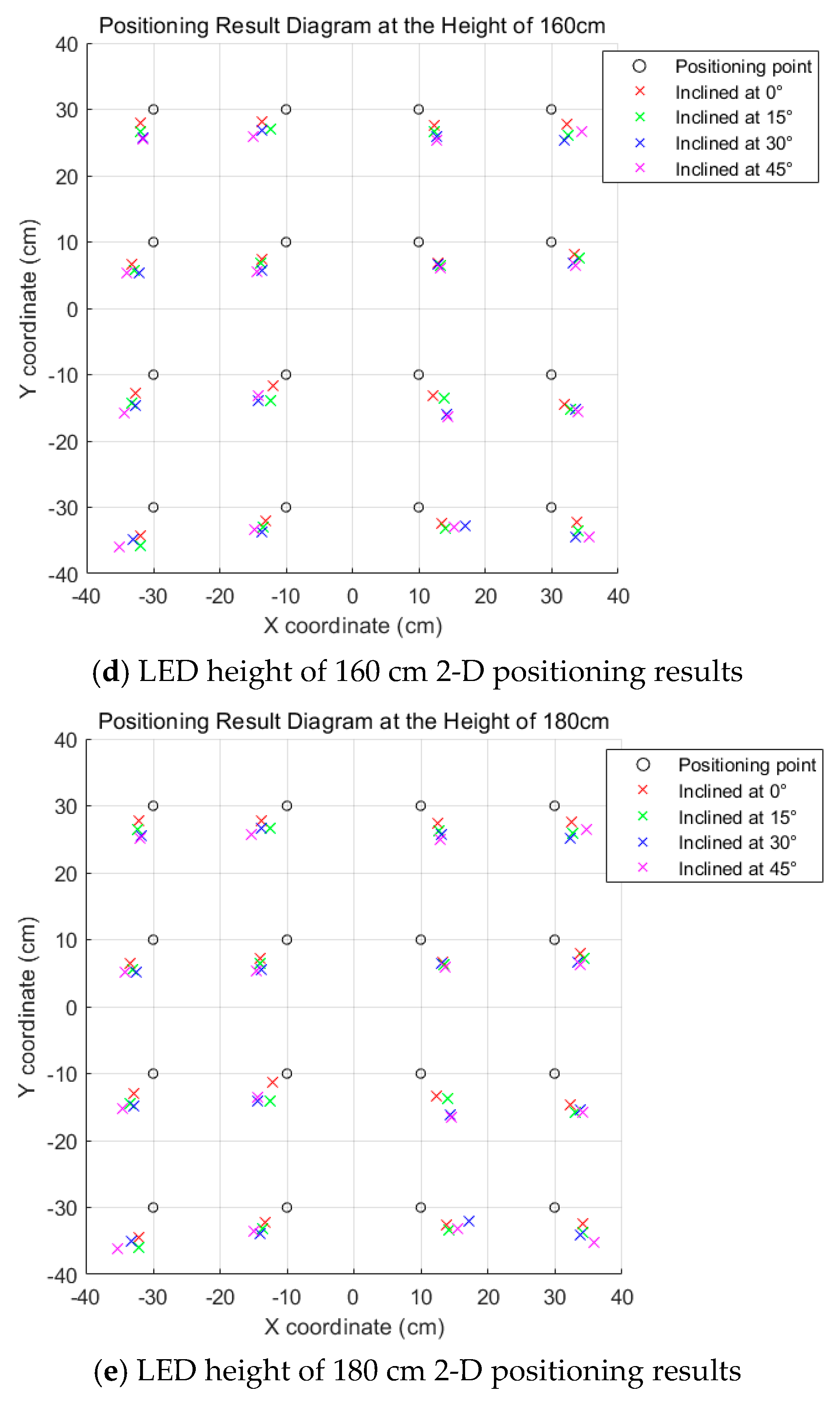
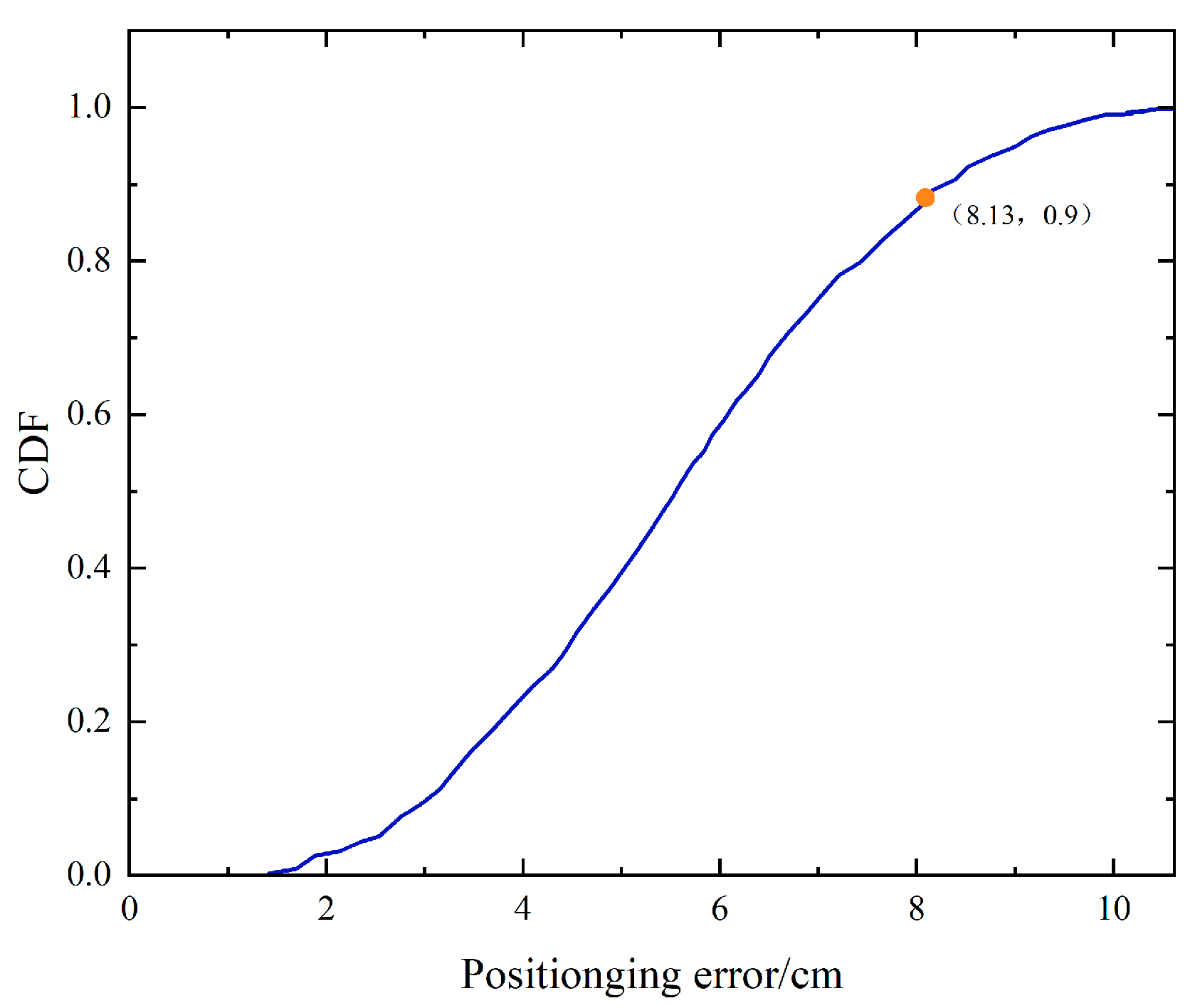
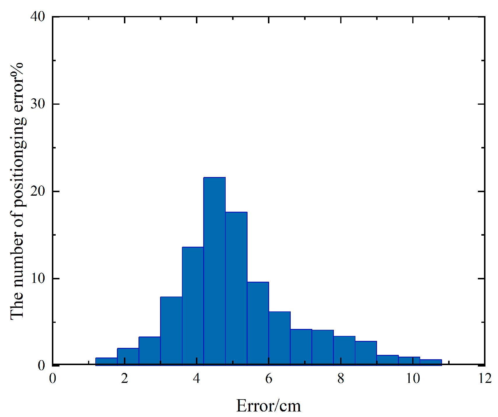
4.2. Experimental Procedure and Result Analysis

The experiment was conducted in the environment on the right of Figure 7, where the lower part is equipped with an optical platform. The receiver is placed on the optical experimental platform, and the actual position of the receiver is determined by the method of coordinate division. The LED lights were placed at different heights (180 cm, 160 cm, 140 cm, 80 cm, and 60 cm from the mobile phone camera), the grid size was divided, and 16 positioning test points were selected. At the same time, in order to reduce accidental errors, the test is repeated 5 times for each position and the average is taken as the final positioning result. In addition, under different height conditions, different phone camera tilt angles (0°, 15°, 30°, 45°) are also introduced. The left half axis of the X-axis is tilted in a clockwise direction, the right half axis is tilted in a counterclockwise direction, and the same experimental tests are performed at these tilt angles.
The visualized positioning results for the real-world coordinates of the positioning point and the calculated world coordinates are shown in Figure 8. Among them, the hollow origin is the positioning test point divided according to the grid, the cross represents the calculated world coordinates, and the cross of different colors represents the positioning results of different tilts. It can be observed from the figure that under diverse positioning conditions, the match between the predicted positions and the actual positions is satisfactory, and the majority of cases with smaller inclination angles result in positioning outcomes closer to the actual coordinates. It has been verified that as the inclination angle gradually increases, the characteristic of elliptical imaging is manifested by a corresponding elongation of its long axis, while the short axis exhibits a tendency of shortening. We adopt the average value of the long and short axes as the imaging radius for positioning calculation, which is feasible. The differences between the actual coordinates and the predicted coordinates of all the test points were statistically analyzed. The results indicate that the average positioning error of all the positioning points is 4.74 cm, and the maximum positioning error is 10.62 cm. Although this value is relatively large, it is still within an acceptable range and has not exerted a significant influence on the overall performance of the system. The minimum positioning error is merely 1.41 cm, suggesting that the system can achieve positioning accuracy at the centimeter level.
In order to intuitively compare the variation trend of the average positioning error when the vertical height of the LED takes different values, we conducted a detailed comparative analysis of the average positioning error under five different vertical heights and multiple incline conditions, and the results are shown in Figure 9. As can be seen from the figure, under the same tilt angle, although the vertical height of the LED changes, the growth trend of the average positioning error is quite flat and there is no significant fluctuation, indicating that the algorithm is less affected by the height change. In addition, under the same vertical height condition, with the gradual increase of the tilt angle, the positioning error increases somewhat but the increase amplitude is also very gentle, which can prove the robustness of the positioning method in the face of different tilt conditions.
For better analysis performance, the cumulative distribution function is used for further analysis, as shown in Figure 10. The results show that the positioning error of 90% of the fixed points is less than 8.13 cm. The error histogram in Figure 11 shows the error distribution directly, and the frequency distribution in different error ranges can be clearly observed. Therefore, it is obvious that the system has a good positioning accuracy in most cases. The positioning error in the experiment mainly stems from several aspects. The first is human error; there is a certain coordinate deviation between the fixed position of the LED light and the position of the receiver. The second IS the system error; the IS process construction and installation factors inevitably introduce distortion, resulting in LED imaging deformation. Finally, the positioning algorithm itself leads to additional errors. The first two kinds of errors are unavoidable, but the proposed method can achieve good positioning accuracy under the influence of these errors. For this paper, future work will focus on further optimizing the positioning algorithm, respectively in the aspect of feature recognition and positioning methods, and consider the impact of background light interference on positioning accuracy, so as to improve the robustness and accuracy of the system.
In our experiment, in order to verify the time performance of the VLP system, the sample data is taken from the test data of the experiment. The average positioning time at each height is shown in Table 2. The calculated average positioning time is 53.54 milliseconds, which is 6.46 milliseconds shorter than that in the literature [14], confirming that the positioning time of the system is up to milliseconds and has good real-time performance.
Compared with traditional positioning methods, the system complexity, positioning accuracy and time efficiency are comprehensively compared, as shown in Table 3. A simple single light positioning system is adopted to reduce the cost of hardware configuration. At the same time, the system still maintains a good performance in positioning accuracy and time efficiency.

5. Conclusions

In this paper, a visible light positioning system based on a single LED lamp is constructed, and experiments are set up to test the performance of the proposed system. Through the proposed LED image detection and recognition algorithm, the image is virtual gridded, and the grid area that may contain the target is processed, thus reducing the total amount of pixels to be processed. Compared with the direct binarization and edge detection of the whole image, this method significantly reduces the time cost of decoding and shape information extraction, and has good real-time performance. At the same time, using the average value of the long axis and the short axis as the imaging radius of the ellipse improves the positioning accuracy and does not increase the complexity of the positioning algorithm compared with using only the long axis. Experimental results show that the proposed positioning method achieves centimeter-level positioning accuracy under different vertical heights and tilt angles. This also means that the proposed scheme is robust and suitable for practical applications.
Indeed, the method proposed in this paper focuses on the application of LED downlights, and future research directions can be expanded to explore various forms of LED luminaires in order to further enhance the practicality and value of the visible light positioning system based on image sensors.

Author Contributions

Conceptualization, X.C. and X.K.; methodology, X.C. and X.K.; software, X.C.; validation, X.C., X.K. and H.Q.; formal analysis, X.C.; investigation, X.C. and H.Q.; resources, X.C. and X.K.; data curation, X.C. and H.Q.; writing—original draft preparation, X.C.; writing—review and editing, X.C., X.K. and H.Q. All authors have read and agreed to the published version of the manuscript.

Funding

Funding was received from the following: the Key Industrial Innovation China Project of Shaanxi Province [grant number 2017ZDCXL-GY-06-01]; the General Project of National Natural Science Foundation of China [grant number 61377080]; the Xi’an Science and Technology Program Fund (2020KJRC0083); the Xi’an Science and Technology Plan [grant number 23KGDW0018-2023].

Institutional Review Board Statement

The study did not require ethical approval.

Informed Consent Statement

The study did not require ethical approval.

Data Availability Statement

The data that support the findings of this study are available from the corresponding author upon reasonable request.

Conflicts of Interest

The authors declare no conflicts of interest.

References

  1. Gu, Y.; Lo, A.; Niemegeers, I. A survey of indoor positioning systems for wireless personal networks. IEEE Commun. Surv. Tutor. 2009, 11, 13–32. [Google Scholar] [CrossRef]
  2. Lin, P.X.; Hu, X.B.; Ruan, Y.K.; Li, H.; Fang, J.; Zhong, Y.; Zheng, H.; Fang, J.; Jiang, Z.L.; Chen, Z. Real-time visible light positioning supporting fast moving speed. Opt. Express 2020, 28, 14503–14510. [Google Scholar] [CrossRef] [PubMed]
  3. Zia, M.T. Visible Light Communication Based Indoor Positioning System. TEM J. 2020, 9, 30–36. [Google Scholar] [CrossRef]
  4. Ke, C.H.; Shu, Y.T.; Liang, J.Y. Research progress of indoor visible light localization. J. Illum. Eng. 2023, 34, 79–89. [Google Scholar]
  5. Xu, Y.Z.; Chen, Z. Visible light 3D positioning system based on light-emitting diode and image sensor. Laser Optoelectron. Prog. 2023, 60, 95–104. [Google Scholar]
  6. Guan, W.P.; Wu, Y.X.; Xie, C.Y.; Chen, H.; Cai, Y.; Chen, Y. High-precision approach to localization scheme of visible light communication based on artificial neural networks and modified genetic algorithms. Opt. Eng. 2017, 56, 106103. [Google Scholar] [CrossRef]
  7. Ji, Y.Q.; Xiao, C.X.; Jian, G.; Ni, J.; Cheng, H.; Zhang, P.; Sun, G. A single LED lamp positioning system based on CMOS camera and visible light communication. Opt. Commun. 2019, 443, 48–54. [Google Scholar] [CrossRef]
  8. Xie, C.Y.; Guan, W.P.; Wu, Y.X.; Fang, L.; Cai, Y. The LED-ID Detection and Recognition Method Based on Visible Light Positioning Using Proximity Method. IEEE Photonics J. 2018, 10, 1–16. [Google Scholar] [CrossRef]
  9. Hossen, M.S.; Park, Y.; Kim, K. Performance improvement of indoor positioning using light-emitting diodes and an image sensor for light-emitting diode communication. Opt. Eng. 2015, 54, 035108–035119. [Google Scholar] [CrossRef]
  10. Kim, J.; Yang, S.; Son, Y.; Han, S. High-resolution indoor positioning using light emitting diode visible light and camera image sensor. IET Optoelectron. 2016, 10, 184–192. [Google Scholar] [CrossRef]
  11. Cheng, H.; Xiao, C.X.; Ji, Y.Q.; Ni, J.; Wang, T. A Single LED Visible Light Positioning System Based on Geometric Features and CMOS Camera. IEEE Photonics Technol. Lett. 2020, 32, 1097–1100. [Google Scholar] [CrossRef]
  12. Jie, H.; Jing, C.; Ran, W. Visible Light Positioning Using a Single LED Luminaire. IEEE Photonics J. 2019, 11, 1–13. [Google Scholar]
  13. Gong, S.B.; Qian, Z.K.; Cao, B.Y. Mechanism of minimum frequency resolution in visible light positioning system. Laser Optoelectron. Prog. 2023, 60, 201–207. [Google Scholar]
  14. Li, H.P.; Huang, H.B.; Xu, Y.Z.; Wei, Z.; Yuan, S.; Lin, P.; Wu, H.; Lei, W.; Fang, J.; Chen, Z. A Fast and High-Accuracy Real-Time Visible Light Positioning System Based on Single LED Lamp With a Beacon. IEEE Photonics J. 2020, 12, 1–12. [Google Scholar] [CrossRef]
  15. Guan, W.P.; Chen, S.H.; Wen, S.S.; Tan, Z.; Song, H.; Hou, W. High-Accuracy Robot Indoor Localization Scheme based on Robot Operating System using Visible Light Positioning. IEEE Photonics J. 2020, 12, 1–16. [Google Scholar] [CrossRef]
  16. Xie, Z.K.; Guan, W.P.; Zheng, J.H.; Zhang, X.J.; Chen, S.H.; Chen, B.D. A High-Precision, Real-Time, and Robust Indoor Visible Light Positioning Method Based on Mean Shift Algorithm and Unscented Kalman Filter. Sensors 2019, 19, 1094. [Google Scholar] [CrossRef]
  17. Liu, X.Y.; Wei, X.T.; Guo, L. DIMLOC: Enabling High-Precision Visible Light Localization Under Dimmable LEDs in Smart Buildings. IEEE Internet Things J. 2019, 6, 3912–3924. [Google Scholar] [CrossRef]
  18. Huang, H.Q.; Lin, B.; Feng, L.H.; Lv, H.C. Hybrid indoor localization scheme with image sensor-based visible light positioning and pedestrian dead reckoning. Appl. Opt. 2019, 58, 3214–3221. [Google Scholar] [CrossRef]
  19. Xu, J.J.; Gong, C.; Xu, Z.Y. Experimental indoor visible light positioning systems with centimeter accuracy based on a commercial smartphone camera. IEEE Photonics J. 2018, 10, 1–17. [Google Scholar] [CrossRef]
  20. Liu, G. Research on 3D Sensor Calibration Algorithm and Software Design. Master’s Thesis, Nanchang University, Nanchang, China, 2015. [Google Scholar]
  21. Guan, W.P.; Wu, Y.X.; Xie, C.Y.; Fang, L.; Liu, X.; Chen, Y. Performance analysis and enhancement for visible light communication using CMOS sensors. Opt. Commun. 2018, 41, 531–545. [Google Scholar] [CrossRef]
  22. Guan, Y.; Sun, D.D.; Yin, S.G. High precision visible light indoor positioning method based on imaging communication. Chin. J. Lasers 2016, 43, 191–198. [Google Scholar]
  23. Zhang, Y.P.; Zhu, X.Q.; Zhu, D.Y. Train location method in visible light imaging communication based on BP neural network. Chin. J. Lasers 2023, 50, 124–134. [Google Scholar]
  24. Béchadergue, B.; Shen, W.-H.; Tsai, H.-M. Comparison of OFDM and OOK modulations for vehicle-to-vehicle visible light communication in real-world driving scenarios. Ad Hoc Netw. 2019, 94, 101944. [Google Scholar] [CrossRef]
  25. Tan, J.; Narendran, N. A driving scheme to reduce AC LED flicker. Opt. Eng. 2013, 8335, 1–6. [Google Scholar]
  26. Hu, X.; Zhang, P.P.; Sun, Y.M.; Deng, X.; Yang, Y.; Chen, L. High-Speed Extraction of Regions of Interest in Optical Camera Communication Enabled by Grid Virtual Division. Sensors 2022, 22, 8375. [Google Scholar] [CrossRef]
  27. Amsters, R.; Demeester, E.; Slaets, P.; Holm, D.; Joly, J.; Stevens, N. Towards Automated Calibration of Visible Light Positioning Systems. In Proceedings of the 2019 International Conference on Indoor Positioning and Indoor Navigation (IPIN) IEEE, Pisa, Italy, 30 September 2019; Volume 8, pp. 1–8. [Google Scholar]
  28. Zhang, Y.P.; Zhu, D.Y.; Ma, J.M. Subway train location based on monocular vision and visible light imaging communication. Laser Optoelectron. Prog. 2022, 59, 69–78. [Google Scholar]
  29. Othman, I.Y.; Neha, C.; Zabin, G. A unilateral 3D indoor positioning system employing optical Camera communications. IET Optoelectron. 2023, 4, 110–119. [Google Scholar]
  30. Le, N.T.; Jang, Y.M. Photography Trilateration Indoor Localization with Image Sensor Communication. Sensors 2019, 19, 3290. [Google Scholar] [CrossRef]
  31. Zhang, R.; Zhong, W.D.; Kemao, Q.; Zhang, S. A single LED positioning system based on circle projection. IEEE Photonics J. 2017, 9, 1–9. [Google Scholar] [CrossRef]
Figure 1. Diagram of the coordinate system transformation process for the imaging model (ad).
Photonics 11 01199 g001
Figure 2. Relation diagram of coordinate system transformation.
Photonics 11 01199 g002
Figure 3. Visible light positioning system architecture.
Photonics 11 01199 g003
Figure 4. Flow chart of image recognition and detection.
Photonics 11 01199 g004
Figure 5. Image processing process.
Photonics 11 01199 g005
Figure 6. Projection of LED light source on image plane.
Photonics 11 01199 g006
Figure 7. System experiment platform.
Photonics 11 01199 g007
Figure 8. Positioning results of different heights.
Photonics 11 01199 g008aPhotonics 11 01199 g008b
Figure 9. Comparison of average positioning errors at different vertical distances.
Photonics 11 01199 g009
Figure 10. CDF diagram of positioning errors.
Photonics 11 01199 g010
Figure 11. Histogram of positioning errors.
Photonics 11 01199 g011
Table 1. Key parameters of the experiment.
ParameterValue
LED luminous diameter/cm17.4
LED drive voltage/V30
LED drive current/A0.1
Camera resolution/pixel2046 × 1080
Exposure time/μs125
ISO50
Focal length/mm3.6
Experimental size/cm80 × 80 × 180
LED coordinates/cm(0, 0, 180)
Table 2. Average Positioning Time for Each Height.
Height/cm6080140160180
Average Positioning Time/ms53.3653.4253.5853.6353.70
Table 3. Comparison of different positioning methods.
ReferenceNumber of LEDs/PCSPositioning
Accuracy/cm
Average Time
Consuming/ms
[5]25.6164.13
[14]1 + Extra mark2.2660
[29]17.56Not given
[30]310Not give
[31]117.52Not give
This paper14.7453.54
Disclaimer/Publisher’s Note: The statements, opinions and data contained in all publications are solely those of the individual author(s) and contributor(s) and not of MDPI and/or the editor(s). MDPI and/or the editor(s) disclaim responsibility for any injury to people or property resulting from any ideas, methods, instructions or products referred to in the content.

