Abstract
In this letter, an integrated dual-user visible light communication and positioning (VLCP) system based on non-orthogonal multiple access (NOMA) is proposed. The system consists of a single light-emitting diode (LED) and five photodiodes (PD), and the adaptive feedback threshold (AFT) algorithm is used to reduce error propagation (EP) to improve noise immunity. The particle swarm optimization (PSO) algorithm is employed to construct a joint optimization function that optimizes the power allocation factor of the two users and the roll-off coefficient of the square-root-raised-cosine(SRRC) filter. The simulation results demonstrate that, in the given indoor environment, the bit error ratio (BER) of each user in the proposed system is lower than the front error correction (FEC) limit and the average positioning errors of the two users are 4.62 cm and 5.74 cm respectively.
1. Introduction
With the rapid development of mobile ultra-wideband, super internet of things (IoT), and artificial intelligence, 6G will provide communication services for a wide range of devices [1,2]. Due to the multipath effect of satellite signals caused by reflections and other factors, global positioning systems (GPS) suffer from poor positioning accuracy in indoor environments. Meanwhile, radio-frequency (RF) based indoor communication and positioning technologies face electromagnetic interference and spectrum shortage problems. Compared to traditional indoor communication and positioning technologies, visible light communication and positioning (VLCP) have the advantages of wide bandwidth, resistance to RF electromagnetic interference, high biosafety and high positioning accuracy at low cost [3,4,5,6]. Therefore, VLCP attracts more attention for providing information transmission and high-precision positioning services for indoor smart terminals such as smart factories and smart homes.
In the visible light communication(VLC) system, the bandwidth of commercial light-emitting diode (LED) is usually several MHz, which becomes one of the difficulties hindering high-speed transmission and multi-user access. To address the issue of limited LED modulation bandwidth and to enable multiple access, researchers have proposed orthogonal multiple access (OMA) and non-orthogonal multiple access (NOMA) techniques. Compared to OMA, NOMA allows multiple users to share resources such as frequency, time, and space within the non-orthogonal resource domain, improving spectral efficiency and thus system capacity [7,8]. The NOMA system assigns higher transmit power to users with poorer channel conditions and lower transmit power to users with better channel conditions, which is fairer compared to the OMA system [9]. In order to improve the throughput of multi-user VLC systems, an adaptive multi-user association strategy based on VLC-NOMA was proposed, which obtained the optimal solution with maximum system capacity under transmission power constraints through power allocation [10]. In order to realize multi-user communication function in a single cell, a two multi-user grouping schemes was proposed, which maximizing the channel difference within the group in downlink VLC-NOMA links [11]. However, NOMA suffers from the problem of inter-user interference, which is traditionally demodulated using serial interference cancellation (SIC), resulting in the phenomenon of error propagation (EP).
Adjustable bit rate superposition coding (ABRSC) and sample-and-sum successive interference cancellation (SSSIC) decoding schemes were proposed to reduce the EP effect on the bit error rate. In the case of poor VLC channel conditions, this solution introduces user bit error factors by reducing user bit rates and continuous interference elimination methods to reduce interference between users to reduce BER [12]. Moreover, in NOMA uplink, a least-reliable symbol-based ordered-successive interference cancelation (LRS-OSIC) algorithm was proposed. The algorithm comprehensively considered spectrum efficiency and transmission reliability while reducing EP [13]. In addition, an optimized optical antenna design and a signal processing method based on successive interference cancellation (SIC) and multi-layer coding (MC) are proposed to address the misalignment problem caused by transmitter/receiver mobility and the interference problem between LEDs [14]. To support multi-user communication in a cell, an improved MMSE algorithm is employed in the MIMO-OFDM VLC system, adding Cyclic Prefix and Suffix to ensure subcarrier orthogonality and reduce multipath interference [15]. To mitigate adjacent interference in dense broadband VLC networks, a joint AP selection and power allocation scheme is proposed, optimizing both to maximize data transmission rates and minimize interference [16]. In recent years, researchers have proposed many VLC systems for NOMA-based systems. Most of the research aims to reduce EP and improve the quality of VLC transmissions, but the VLCP system based on the NOMA structure has not yet been proposed.
Recently, techniques based on time difference of arrival (TDOA), angle of arrival (AOA), and received signal strength (RSS) have been proposed to achieve visible light positioning (VLP) [17,18,19,20]. Meanwhile, to support multi-user positioning services within an integrated system, an indoor VLP system based on code division multiple access (CDMA) and optical orthogonal codes (OOC) was proposed to enhance communication performance [21,22]. To fulfill the VLC and VLP functions simultaneously, the positioning subcarrier and the communication subcarrier were used for communication and positioning respectively to build an orthogonal frequency division multiple access (OFDMA) based VLCP system [23,24]. To avoid signal interference without disrupting the existing VLC protocol, the mode of inserting an optically detected spreading plug-in based on the VLC frame structure was proposed [25]. In order to solve the problem of resource competition in the integrated communication and positioning system, a multi-scale non-orthogonal multiple access waveform and a novel communication and positioning performance constrained positioning power allocation algorithm was proposed [26]. In order to improve the positioning accuracy in the absence of line-of-sight (LOS) signal loss and focus on the visible light positioning system based on intelligent reflective surface(IRS), the Cramér lower bound (CRLB) expression and maximum likelihood (ML) estimator applicable and an optimization adjustment method were proposed [27]. However, resource competition and overall system performance degradation could occur in VLCP systems due to the scheme of adding additional positioning signals. In recent years, researchers have studied a variety of VLP systems for different application scenarios, but the NOMA-VLP system has not yet been proposed.
To address the above problems, this letter proposes a dual-user VLCP system based on baseband NOMA. The main contributions of this letter are summarized as follows: (1) A baseband NOMA-VLCP system without extra positioning power is proposed to solve the problem of resource competition between communication and positioning services; (2) A joint optimization function including the communication performance and positioning accuracy is designed to improve the system transmission and positioning performance; (3) The performance of the proposed system is analyzed and verified in simulation. The letter is organized as follows: Section 2 presents the proposed system model, Section 3 presents the simulation and experimental results and Section 4 concludes the letter.
2. System Module and Optimization Algorithm
Figure 1 shows the proposed dual-user NOMA VLCP system without SIC where data from each user is passed through a square root-derived cosine filter (SRRC), maximal ratio combining (MRC) and Volterra equalizer. This system uses a single LED as the signal transmitter, placed in the center of the ceiling. Since there is spectrum overlap between two users in the baseband NOMA system and a SIC-free decision method is used at the receiving end, the receiver only needs to process the light intensity information without considering frequency, phase, and other information, each will be coded signal using on-off keying (OOK) modulation.To reduce inter-user interference and improve communication and positioning performance, particle swarm optimization (PSO) algorithm was used to optimize the system parameters. During the optimization process, the signal bandwidth changes due to the change of the roll-off factor, the bit rate of each user satisfies , Bitstream undergoes shaping through an SRRC filter, the shaping function for user i being [28]:
where is the duration of a single code element for user i, is the SRRC filter roll-off coefficient corresponding to the user i. After applying the SRRC filter, the signal transmitted by user i is represented as:
where is the signal after modulation by OOK, is the power allocation factor of user i and , k is the number of bits in the data stream after encoding for each user. Superimposed in the power domain and adding a DC bias to drive the LED, the emitted signal can be expressed as:
where is the total number of subscribers in a single cell, and is the LED DC bias. According to the Lambertian radiation model, the channel gain of the line-of-sight (LOS) link can be expressed as [29]:
where m is Lambertian radiation coefficient, A is the physical area of the detector for PD, d is the transmission distance from the LED light source to each photodetector, The angle of radiation and the angle of incidence is denoted as and , and are the gain of the optical filter and concentrator. Through the LOS channel, the received signal of the - PD is referred to as:
where is the responsiveness of the PD, is Gaussian white noise. The receiver uses one horizontal PD and four oblique PDs to form a common receiver, and the signal received by the - PD is filtered by SRRC to obtain the signal of user i expressed as:
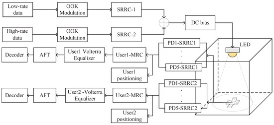
Figure 1.
The proposed integrated baseband VLCP system.
MRC is suitable for optimal combining in independent additive Gaussian white noise channels, which is widely used in VLC systems [30]. For the VLC system proposed in this letter, the receiving end consists of one horizontal PD and four inclined PDs. After MRC, the signal received by each PD from user i can be expressed as [31]:
where is the number of merged branches, while in the system proposed in this letter, the number of branches is equal to the number of PDs in the receiver, is the gain of the j- merged branch, is the merging coefficient of each branch in the MRC, the branch weighting coefficients are determined by the adaptive feedback threshold (AFT) extracted from the corresponding PDs, is the noise of the j- PD, and the noise model can be regarded as Gaussian white noise, expressed as [32]:
The signal-to-noise ratio (SNR) is the ratio of the received signal power to the noise power, where the noise includes shot noise and thermal noise, with and respectively. The horizontal PD is set as PD1 and the received optical power used for positioning is estimated based on the signal threshold of each PD. AFT-based multi-PD positioning is achieved by calculating the Received optical power ratio (ROPR), which can be expressed as:
where represents the power of the optical signal received by the j- PD of the user i. The threshold value of the signal received by each PD is determined after AFT. The threshold value of the received signal and the LOS link gain of the visible light channel show a positive correlation. To facilitate the subsequent calculation formula derivation, the expression is set as follows:
where is the tilt angle of the tilted PD relative to the horizontal plane, represents the angle between the center PD and the line connecting the i-th tilted PD on the x-y axis plane, constructs the auxiliary parameter azimuth angle . X and are the coordinates of the LED, r represents the distance from the center of the tilted PD to the center of the horizontal PD in the direction parallel to the tilted plane, and h is the height between the LED and the receiving PD.The receiver consists of a horizontal PD and four tilted PDs, providing five received optical power parameters. Since the transmitter position is fixed, by adjusting the tilt angles of the four tilted PDs, the incident angles () are different. Combined with Equation (4), the PD received optical power is different, resulting in four received optical power ratio parameters, and the position information is obtained under the premise that the receiver parameters are known [32].
Hence, the current position can be expressed as the coordinates of the four tilted PDs:
For VLC, to reduce the interference between users, the user i signal is represented by the Volterra equalizer as:
The length of the linear part of the Volterra equalizer is represented by , while represents the length of the nonlinear part. and represent the first and second order Volterra kernels, respectively. The demodulated signal using the AFT algorithm of user i can be shown as:
where denotes the baseband signal demodulation algorithm based on AFT. This algorithm is a dynamic decision algorithm without SIC. Two users generate a training sequence and obtain the initial decision threshold. In a symbol period of each user, the weighted summation and averaging operation is performed on the signal within the period to achieve demodulation of the two user signals and update the decision threshold [31]. In this paper, SINR is used as a measure of communication performance to participate in the optimization operation. In the system proposed in this paper, the SINR when two user signals are demodulated is expressed as:
where represents the power compression factor of the volterra equalizer, represents the compression parameters related to , and :
To optimize the system performance containing the user fairness, the PSO algorithm is used to optimize the user power allocation factor and the SRRC roll-off coefficient under the premise of both the communication and positioning performance. The PSO algorithm mathematical expression and objective function are set as [33]:
Due to the characteristics of PSO being easy to implement and having a high degree of parallelism, the PSO algorithm is used to optimize the system parameters. The parameters in the optimization process are set as follows: the number of populations is set to 40, the maximum number of iterations is set to 60, the self-learning factor and the group learning factor are both 0.5, the initial population information is randomly generated by the three parameters within the allowable range, the population iteration speed of and parameters is −0.0125 to 0.0125 and −0.015 to 0.015, respectively, and the search range is 0.2 to 0.7 and 0.1 to 0.7, respectively, and the search speed is limited to −0.015 to 0.015, and the search range is 0.3 to 0.8. To this end, the following objective function is constructed:
It can be seen in Equations (11) and (12) that RSSR positioning depends only on signal strength, not on correct demodulation of symbols. Therefore, changes in symbol error rate have little impact on RSSR itself. In addition, if the channel conditions are poor, it may lead to inaccurate extraction of received signal strength, which will indirectly affect RSSR calculation. Therefore, in order to meet the requirements of positioning accuracy and BER at the same time, the influence of both on the numerical value of the optimization objective function is comprehensively considered in the system parameter optimization part, and a compensation factor is introduced to make the positioning error and communication performance weight the same. where is the compensation factor that balances the signal-to-interference plus noise ratio (SINR)with the positioning error. represents the maximum positioning error allowed by the system, while represents the average positioning error. represents the fairness factor of the positioning error. represents the SINR of the user i obtained by the model estimation. represents the fairness factor of each user’s SINR. , and are denoted as:
3. Simulation Results and Discussion
In this section, the performance of the proposed SIC-free VLCP system is simulated based on the PSO optimization algorithm to reduce the inter-user interference and the AFT demodulation algorithm to avoid EP. The structure of the proposed system is compared with that of the traditional VLCP system with SIC. The system proposed has a rate of 1 Mb/s for user 1 and 20 Mb/s for user 2. The following studies are based on this rate. The system is deployed in the indoor space of 5 m × 5 m × 2.5 m, where the LED coordinates are (2.5 m, 2.5 m, 2.5 m), and the emitting power of LED, area of the PD and related parameters are shown in Table 1.

Table 1.
Simulation parameters.
To reflect the characteristics of the superimposed signals in the power domain of the system, the time domain characteristics of the superimposed signals, after filtered by SRRC, are shown in Figure 2a, and the total time length of the signals is 500 μs. Figure 2b displays the spectrum of the originating signal in the proposed system. The red spectrum represents the user 1 signal, the blue spectrum represents the user 2 signal, and the green spectrum represents the superimposed Gaussian white noise. Each user’s signal is processed separately by the SRRC. User 1 has a bandwidth of approximately 0.6 MHz, while User 2 has a bandwidth of approximately 18 MHz There is a significant bandwidth gap between the users, which helps to reduce user interference.
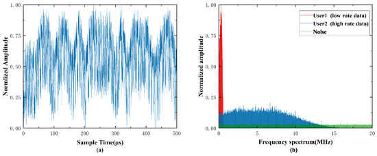
Figure 2.
Power superimposed signal (a) Time domain characteristics (b) Frequency domain characteristics.
Figure 3 shows the convergence curves of the objective function, SINR, and positioning accuracy of the system using PSO. The PSO algorithm was limited to a total of 60 iterations during the simulation. Figure 3a shows that the objective function converges with acceptable fluctuation. The optimization algorithm for this system has an upper limit of 10 cm positioning error. It can be attributed to the compensation factor providing higher sensitivity. Figure 3b displays the optimization targets of the communication and positioning services. As the number of iterations increases, the system’s SINR converges and its positioning accuracy improves. This optimization scheme incorporates a compensation factor to balance the emphasis on positioning accuracy and SINR. Owing to the use of random data during the optimization process, which estimates the user’s SINR and positioning errors, the target optimization function exhibits fluctuations within a specific range. As a result, the overall optimization function fluctuates constantly with the increase in the number of iterations, and the minimum positioning error during the iteration process is 2.01 cm.
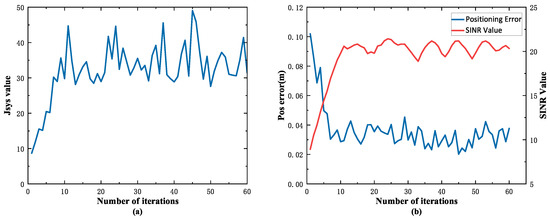
Figure 3.
Optimization process of PSO algorithm (a) objective function optimization process (b) optimization curve of SINR and positioning error.
The positioning performance of the proposed system is shown in Figure 4, where Figure 4a,b show the positioning results in the receiving plane when the device is deployed in an environment with a height of 2.5 m and 3 m, respectively. Comparing Figure 4a,b, increases in height from 2.5 m to 3 m result in a smaller effect on the positioning error. The simulation results indicate that the proposed system achieves a positioning error of each user within 10 cm, where the average positioning error of user 1 is 4.50 cm and that of user 2 is 4.12 cm at a height of 2.5 m. In the environment with a height of 3 m, the average positioning error of user 1 is 4.62 cm and the average positioning error of user 2 is 5.74 cm.

Figure 4.
Positioning performance of the VLCP system (a) at a height of 2.5 m and (b) at a height of 3 m.
Figure 5a demonstrates that the proposed VLCP system can significantly reduce the average positioning error of multi-users. The average positioning error of the proposed VLCP system in this letter is 4.31 cm, and the lower 0.9 quartile of the positioning error is 5.43 cm. In comparison, the average positioning error of the traditional VLP system is 11.9 cm, and the lower 0.9 quartile of the positioning error is 16.7 cm. To investigate the positioning capability of the system under poor channel conditions, we compared the positioning accuracy of the proposed system with that of the conventional system as a function of the SNR, as shown in Figure 5b.
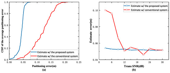
Figure 5.
Comparison of localization performance of different algorithms (a) CDF of system positioning error (b) mean position error versus SNR.
The simulation results in Figure 5 indicate that the proposed system’s positioning error remains under 6 cm even under lower SNR conditions, demonstrating its good anti-interference characteristic. Compared to VLCP systems equipped with SIC, this system implements the AFT mechanism and does not exhibit EP. Here, user positioning accuracy is primarily influenced by the SINR. Therefore, the system can provide high-precision positioning services for indoor devices.
In the environment, the BER of user 1 and user 2 are represented in Figure 6a,b, respectively. For user 1, BER in the receiving plane remains relatively stable within a certain range. Additionally, for low-speed signals, the impact of inter-user interference from high-speed signals on communication performance is more significant than that of additive Gaussian white noise. The BER of user 2 is more strongly affected by Gaussian white noise, from the Lambertian radiation model, the noise power shows a negative correlation with the distance of the signal transmission. Therefore, in this system, reducing the transmission distance of high-speed signals appropriately can decrease the BER and improve communication performance. As illustrated in Figure 6b, the BER of user 2 is the lowest directly beneath the LED in the receiving plane. Moving towards the center point of the receiving plane, the BER gradually increases until it reaches its maximum at the edge point of the receiving plane. Figure 6c,d show the BER of each user in the indoor environment. With the two figures, the position change has less effect on the BER of low-speed signals, while for high-speed signals, it is more affected by the superimposed noise. Therefore, the overall distribution of the BER of high-speed signals in the receiving plane follows a similar trend to that in Figure 6b. From a comprehensive analysis of Figure 6, as the signal transmission height increases, the SINR of the received signal for each user decreases, resulting in diminished BER quality. Simulation results show that the BER of each user in the receiving plane is lower than the error correction limit of FEC coding, which demonstrates that the system has anti-interference characteristics.
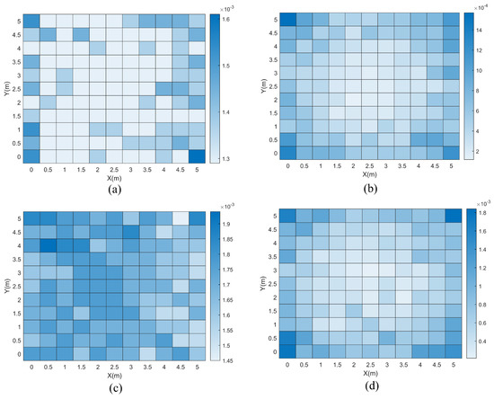
Figure 6.
System BER simulation (a) 2.5 m height, BER for user1 (b) 2.5 m height, BER for user2 (c) 3 m height, BER for user1 and (d) 3 m height, BER for user2.
Figure 7 illustrates that the BER decreases as the SNR increases for both the proposed VLCP system and the conventional VLCP system discussed in this study. The BER in the conventional VLCP system decreases more sharply due to the effect of error propagation (EP), a result of the SIC model employed. As SNR increases, the BER of user 1 declines, reducing EP’s impact on user 2’s signal judgment and thus lowering user 2’s BER. Conversely, the proposed AFT-based VLCP system eliminates EP between users, and communication performance is primarily governed by SINR. In this system, user 1 exhibits a higher BER than user 2, particularly in high-SINR scenarios, where the BER of user 1 exceeds that of the conventional system. This is due to the absence of a SIC module, as the AFT-based method does not suppress user 1’s signal during decision-making, nor does it improve user 2’s SINR. Consequently, as SNR increases, the SINR for both users stabilizes under fixed power allocation, leading to minimal BER variation. Notably, the AFT-based system demonstrates superior anti-interference capabilities compared to the SIC-based VLC system and maintains reliable communication even under low-SNR conditions.
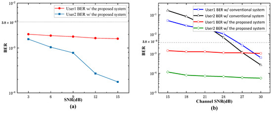
Figure 7.
BER with different channel SNR. (a) low SNR. (b) high SNR.
Since the system uses a single-LED multi-PD structure, the multi-LED NOMA-VLCP structure is analyzed, including the communication performance and positioning performance of the system. In terms of communication performance, the increased number of LEDs can provide higher total transmission power and more signal paths, thereby improving the channel gain and signal-to-noise ratio at the receiving end, which is helpful in solving the problem of different signal strengths. Since the system is a non-SIC system, the addition of LEDs may aggravate the interference between multiple users, resulting in an increase in the bit error rate (BER) of remote users. The signal interference within the cell can be reduced by optimizing the power allocation and multiplexing scheme.
The positioning part of this system uses a single LED positioning solution. Since the receiver structure parameters are known, the relative position of the center PD and the LED is obtained by the ratio of the received signal strength. Adding LEDs is not very applicable to the current system. However, increasing the number of LEDs provides richer geometric information. The receiver can use multi-source signals for triangulation or signal strength analysis to improve positioning accuracy. However, as the number of LEDs increases, signal interference may occur within the cell. If there is no multiplexing, it may lead to a decrease in positioning performance.
4. Conclusions
In this letter, we propose a dual-users rate VLCP system architecture with no SIC process and can effectively avoid EP compared with the traditional baseband NOMA. Based on the combination of user rates of this system, the PSO algorithm is used to optimize the power allocation factor and system parameters to reduce inter-user interference. Simulation results show that in the indoor environment of , the communication BER of each user is lower than the FEC error correction limit, and still meets the communication requirements under the condition of low channel SNR. The proposed VLCP system can realize centimeter-level positioning for signals of different rates, with an average positioning error of 4.31 cm, which reduces the average positioning error by 63.74% when compared with the baseband NOMA-VLP system with SIC. Expanding the system environment to , the average positioning accuracy of the system is 5.15 cm and meets the communication needs of different users. To this end, the proposed VLCP system can provide information transmission and high-precision positioning services for smart terminals in indoor environments.
Author Contributions
Conceptualization and methodology, J.J.; software and validation, Q.S.; investigation and resources, J.W.; data curation and visualization, H.L.; writing—original draft preparation, D.C.; writing—review and editing, D.Y. All authors have read and agreed to the published version of the manuscript.
Funding
This work was financed by the Guangdong Basic and Applied Basic Research Foundation, China (2022A1515110154, 2021B1515120086, 2022A1515110770), Fundamental Research Funds for the Central Universities, China (FRF-TP-22-049A1, FRF-TP-22-044A1), National Natural Science Foundation of China (62374015).
Institutional Review Board Statement
Not applicable.
Informed Consent Statement
Not applicable.
Data Availability Statement
The data presented in this study are available upon request from the corresponding author.
Conflicts of Interest
The authors declare no competing interests. The author Dongmei Yang was employed by the company World Telecom Satellite Technology Limited. There are no conflict of interest between any of the authors and the company.
References
- Zhang, L.; Liang, Y.C.; Niyato, D. 6G Visions: Mobile Ultra-Broadband, Super Internet-of-Things, and Artificial Intelligence. China Commun. 2019, 16, 14. [Google Scholar] [CrossRef]
- Wang, C.X.; You, X.; Gao, X.; Zhu, X.; Li, Z.; Zhang, C.; Wang, H.; Huang, Y.; Chen, Y.; Haas, H.; et al. On the Road to 6G: Visions, Requirements, Key Technologies, and Testbeds. IEEE Commun. Surv. Tutor. 2023, 25, 905–974. [Google Scholar] [CrossRef]
- Li, X.; Zhang, R.; Hanzo, L. Optimization of Visible-Light Optical Wireless Systems: Network-Centric Versus User-Centric Designs. IEEE Commun. Surv. Tutor. 2018, 20, 1878–1904. [Google Scholar] [CrossRef]
- Abuella, H.; Elamassie, M.; Uysal, M.; Xu, Z.; Serpedin, E.; Qaraqe, K.A.; Ekin, S. Hybrid RF/VLC Systems: A Comprehensive Survey on Network Topologies, Performance Analyses, Applications, and Future Directions. IEEE Access 2021, 9, 160402–160436. [Google Scholar] [CrossRef]
- Zhuang, Y.; Hua, L.; Qi, L.; Yang, J.; Cao, P.; Cao, Y.; Wu, Y.; Thompson, J.; Haas, H. A Survey of Positioning Systems Using Visible LED Lights. IEEE Commun. Surv. Tutor. 2018, 20, 1963–1988. [Google Scholar] [CrossRef]
- Chaudhary, N.; Alves, L.N.; Ghassemblooy, Z. Current Trends on Visible Light Positioning Techniques. In Proceedings of the 2019 2nd West Asian Colloquium on Optical Wireless Communications (WACOWC), Tehran, Iran, 27–28 April 2019; pp. 100–105. [Google Scholar]
- Tsai, C.T.; Cheng, C.H.; Kuo, H.C.; Lin, G.R. Toward high-speed visible laser lighting based optical wireless communications. Prog. Quantum Electron. 2019, 67, 100225. [Google Scholar] [CrossRef]
- Song, J.; Cao, T.; Zhang, H. A low complexity NOMA scheme in VLC systems using pulse modulations (invited paper). In Proceedings of the 2020 29th Wireless and Optical Communications Conference (WOCC), Newark, NJ, USA, 1–2 May 2020. [Google Scholar]
- Dai, L.; Wang, B.; Ding, Z.; Wang, Z.; Chen, S.; Hanzo, L. A Survey of Non-Orthogonal Multiple Access for 5G. IEEE Commun. Surv. Tutor. 2018, 20, 2294–2323. [Google Scholar] [CrossRef]
- Li, Q.; Shang, T.; Tang, T.; Xiong, Z. Adaptive User Association Scheme for Indoor Multi-User NOMA-VLC Systems. IEEE Wirel. Commun. Lett. 2023, 12, 873–877. [Google Scholar] [CrossRef]
- O K, H.S.; Sah, A.K. Multi-User Grouping for NOMA Enabled VLC System. IEEE Commun. Lett. 2024, 28, 1072–1076. [Google Scholar] [CrossRef]
- Cao, T.; Zhang, H.; Song, J. BER Performance Analysis for Downlink Nonorthogonal Multiple Access with Error Propagation Mitigated Method in Visible Light Communications. IEEE Trans. Veh. Technol. 2021, 70, 9190–9206. [Google Scholar] [CrossRef]
- Makkar, R.; Rawal, D.; Sharma, N.; Gupta, A. Performance analysis of least reliable symbol based ordered successive interference cancelation detection method for uplink NOMA. Int. J. Commun. Syst. 2022, 35, e5333. [Google Scholar] [CrossRef]
- Wei, J.; Gong, C.; Huang, N.; Xu, Z. Channel Modeling and Signal Processing for Array-Based Visible Light Communication System Under Link Misalignment. IEEE Photonics J. 2022, 14, 1–10. [Google Scholar] [CrossRef]
- Yang, L.; Lin, S.; Li, M. Interference Management for Multi-cell Indoor Visible Light Communication Systems. In Proceedings of the 2023 6th International Conference on Communication Engineering and Technology (ICCET), Xi’an, China, 24–26 February 2023; pp. 161–166. [Google Scholar]
- Miao, P.; Chen, G.; Pang, L.; Pu, X.; Yao, Y.; Chen, P. Joint AP Selection and Power Allocation for Interference Management in Visible Light Communication Networks. In Proceedings of the 2023 IEEE 23rd International Conference on Communication Technology (ICCT), Wuxi, China, 20–22 October 2023; pp. 1498–1502. [Google Scholar]
- Wang, T.Q.; Sekercioglu, Y.A.; Neild, A.; Armstrong, J. Position Accuracy of Time-of-Arrival Based Ranging Using Visible Light with Application in Indoor Localization Systems. J. Light. Technol. 2013, 31, 3302–3308. [Google Scholar] [CrossRef]
- Hong, C.Y.; Wu, Y.C.; Liu, Y.; Chow, C.W.; Chen, Y.Y. Angle-of-Arrival (AOA) Visible Light Positioning (VLP) System Using Solar Cells with Third-Order Regression and Ridge Regression Algorithms. IEEE Photonics J. 2020, 12, 1–5. [Google Scholar] [CrossRef]
- Hsu, C.W.; Liu, S.; Lu, F.; Chow, C.W.; Chang, G.K. Accurate Indoor Visible Light Positioning System utilizing Machine Learning Technique with Height Tolerance. In Proceedings of the Optical Fiber Communication Conference, San Diego, CA, USA, 11–15 March 2018. [Google Scholar]
- Bastiaens, S.; Alijani, M.; Joseph, W.; Plets, D. Visible Light Positioning as a Next-Generation Indoor Positioning Technology: A Tutorial. IEEE Commun. Surv. Tutor. 2024, 26, 2867–2913. [Google Scholar] [CrossRef]
- Yamaguchi, S.; Mai, V.V.; Thang, T.C.; Pham, A.T. Design and performance evaluation of VLC indoor positioning system using optical orthogonal codes. In Proceedings of the IEEE Fifth International Conference on Communications & Electronics, Da Nang, Vietnam, 30 July–1 August 2014. [Google Scholar]
- Park, J.K.; Woo, T.G.; Kim, M.; Kim, J.T. Hadamard Matrices Design for Low-cost Indoor Positioning System in Visible Light Communication. IEEE Photonics J. 2017, 9, 1–10. [Google Scholar] [CrossRef]
- Lin, B.; Tang, X.; Ghassemlooy, Z.; Lin, C.; Li, Y. Experimental Demonstration of an Indoor VLC Positioning System Based on OFDMA. IEEE Photonics J. 2017, 9, 1–9. [Google Scholar] [CrossRef]
- Xu, Y.; Wang, Z.; Liu, P.; Chen, J.; Han, S.; Yu, C.; Yu, J. Accuracy analysis and improvement of visible light positioning based on VLC system using orthogonal frequency division multiple access. Opt. Express 2017, 25, 32618–32630. [Google Scholar] [CrossRef]
- Yu, C.; You, X.; Liu, Z.; Chen, J. Conceptual Design for Indoor Visible Light Communication and Positioning Cooperative Systems. In Proceedings of the 2020 22nd International Conference on Transparent Optical Networks (ICTON), Bari, Italy, 19–23 July 2020. [Google Scholar]
- Yin, L.; Cao, J.; Ni, Q.; Ma, Y.; Li, S. Design and Performance Analysis of Multi-Scale NOMA for Future Communication-Positioning Integration System. IEEE J. Sel. Areas Commun. 2022, 40, 1333–1345. [Google Scholar] [CrossRef]
- Kokdogan, F.; Gezici, S. Intelligent Reflecting Surfaces for Visible Light Positioning Based on Received Power Measurements. IEEE Trans. Veh. Technol. 2024, 73, 13108–13121. [Google Scholar] [CrossRef]
- Hua, J.; Ruan, C.; Zheng, Z.; Wu, Y.; Meng, L. Comparative study of applications of square root raised cosine filter and low pass filter in Digital Down Converter. In Proceedings of the International Conference on Automatic Control and Artificial Intelligence (ACAI 2012), Xiamen, China, 3–5 March 2012; pp. 654–658. [Google Scholar]
- Komine, T.; Nakagawa, M. Fundamental analysis for visible light communication system using LED light. IEEE Trans. Consum. Electron. 2004, 50, 100–107. [Google Scholar] [CrossRef]
- Wang, F.; Liu, Y.; Jiang, F.; Chi, N. High speed underwater visible light communication system based on LED employing maximum ratio combination with multi-PIN reception. Elsevier Opt. Commun. 2018, 425, 106–112. [Google Scholar] [CrossRef]
- Jin, J.; Lu, H.; Wang, J.; Huang, J.; Feng, L.; Chen, D.; Chen, H.; Dong, T.; Su, Y.; Wang, Y. Adaptive feedback threshold based demodulation for mobile visible light communication and positioning integrated system. Opt. Express 2022, 30, 13331–13344. [Google Scholar] [CrossRef] [PubMed]
- Yu, X.; Wang, J.; Lu, H. Single LED-Based Indoor Positioning System Using Multiple Photodetectors. IEEE Photonics J. 2018, 10, 1–8. [Google Scholar] [CrossRef]
- He, Z.; Zhang, S.; Hu, J.; Dai, F. An adaptive time series segmentation algorithm based on visibility graph and particle swarm optimization. Phys. A Stat. Mech. Its Appl. 2024, 636, 129563. [Google Scholar] [CrossRef]
Disclaimer/Publisher’s Note: The statements, opinions and data contained in all publications are solely those of the individual author(s) and contributor(s) and not of MDPI and/or the editor(s). MDPI and/or the editor(s) disclaim responsibility for any injury to people or property resulting from any ideas, methods, instructions or products referred to in the content. |
© 2024 by the authors. Licensee MDPI, Basel, Switzerland. This article is an open access article distributed under the terms and conditions of the Creative Commons Attribution (CC BY) license (https://creativecommons.org/licenses/by/4.0/).