Telescope Alignment Method Using a Modified Stochastic Parallel Gradient Descent Algorithm


Abstract
1. Introduction
2. Theory
- (1)
- Step 1: Parameter settings. As mentioned regarding the theory, some parameters should be given.
- (2)
- Step 2: Image acquisition should be carried out. Images in both on-axis and off-axis fields of view should be collected for wide fields of view telescopes, then merit functions should be calculated.
- (3)
- Step 3: Control variables are perturbed. In this paper, bilateral perturbation is used to improve the stability of the algorithm. Variations of merit functions are computed, according to which, the gradient of merit functions is calculated. Then, the first moment estimation and second moment estimation of the gradient are figured up.
- (4)
- Step 4: Merit functions of images corresponding to the new positions are calculated. The new positions of the secondary mirror or third mirror can be obtained according to the iterative formula, and images in both on-axis and off-axis fields are acquired. Then, merit functions are computed.
- (5)
- Step 5: Determine whether the iteration is terminated. The criterion can be iteration numbers or threshold of merit functions. If the results satisfy the criterion, the iteration is terminated, otherwise, the next iteration will be implemented until the results meet the requirements.
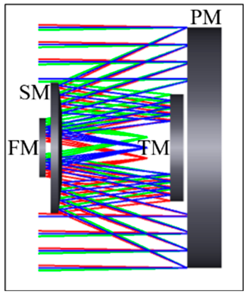
3. Simulations
3.1. Results of Secondary Mirror Alignment
3.2. Results of Secondary Mirror and Third Mirror Alignment
4. Conclusions
Author Contributions
Funding
Institutional Review Board Statement
Informed Consent Statement
Data Availability Statement
Conflicts of Interest
References
- Yao, P.; Liu, R.; Broggini, T.; Thunemann, M.; Kleinfeld, D. Construction and use of an adaptive optics two-photon microscope with direct wavefront sensing. Nat. Protoc. 2023, 18, 3732–3766. [Google Scholar] [CrossRef] [PubMed]
- Li, M.; Liu, X.; Zhang, A.; Zhang, J.B.; Xian, H. A Secondary Mirror Alignment Method for Segmented Telescopes Using a Wavefront Sensor-Less Method. IEEE Photonics Technol. Lett. 2024, 36, 453–456. [Google Scholar] [CrossRef]
- Wu, X.S.; Huang, L.H.; Gu, N.T. Enhanced-resolution Shack–Hartmann wavefront sensing for extended objects. Opt. Lett. 2023, 48, 5691–5694. [Google Scholar] [CrossRef] [PubMed]
- Correia, C.M.; Fauvarque, O.; Bond, C.Z.; Chambouleyron, V.; Sauvage, J.F.; Fusco, T. Performance limits of adaptive-optics/high-contrast imagers with pyramid wavefront sensors. Mon. Not. R. Astron. Soc. 2020, 495, 4380–4391. [Google Scholar] [CrossRef]
- Bailén, F.J.; Suárez, D.O.; Rodríguez, J.B.; Del Toro Iniesta, J.C. Optimal Defocus for Phase Diversity Wave Front Retrieval. Astrophys. J. Suppl. Ser. 2022, 263, 8–16. [Google Scholar] [CrossRef]
- Quesnel, M.; de Xivry, G.O.; Louppe, G.; Absil, O. A deep learning approach for focal-plane wavefront sensing using vortex phase diversity. Astron. Astrophys. 2022, 668, A36–A42. [Google Scholar] [CrossRef]
- Wong, A.; Pope, B.; Desdoigts, L.; Tuthill, P.; Norris, B.; Betters, C. Phase retrieval and design with automatic differentiation: Tutorial. JOSA B 2021, 38, 2465–2478. [Google Scholar] [CrossRef]
- Schlawin, E.; Beatty, T.; Brooks, B.; Nikolov, N.K.; Greene, T.P.; Espinoza, N.; Glidic, K.; Baka, K.; Egami, E.; Stansberry, J.; et al. JWST NIRCam defocused imaging: Photometric stability performance and how it can sense mirror tilts. Publ. Astron. Soc. Pac. 2023, 135, 018001. [Google Scholar] [CrossRef]
- Chambouleyron, V.; Sengupta, A.; Salama, M.; van Kooten, M.; Gerard, B.L.; Haffert, S.Y.; Cetre, S.; Dillon, D.; Kupke, R.; Jensen-Clem, R.; et al. Using the Gerchberg–Saxton algorithm to reconstruct nonmodulated pyramid wavefront sensor measurements. Astron. Astrophys. 2024, 681, A48–A58. [Google Scholar] [CrossRef]
- He, X.; Luo, J.; Wang, J.; Zhang, X.; Liu, Y. Improvement of a computer-aided alignment algorithm for the nonsymmetric off-axis reflective telescope. Appl. Opt. 2021, 60, 2127–2140. [Google Scholar] [CrossRef]
- Lau, K.; Breckenridge, B.; Nerheim, N.; Redding, D. Active figure maintenance control using an optical truss laser metrology system for a space-based far-IR segmented telescope. In Proceedings of the Controls for Optical Systems, Orlando, FL, USA, 21–22 April 1992; Volume 1696, pp. 60–82. [Google Scholar]
- Chen, C.J.; Lin, P.D.; Jywe, W.Y. An optoelectronic measurement system for measuring 6-degree-of-freedom motion error of rotary parts. Opt. Exp. 2007, 15, 14601–14617. [Google Scholar] [CrossRef] [PubMed]
- Martin, S.R.; Rud, M.; Stern, D.K.; Scowen, P.A.; Nissen, J.; Krist, J. HabEx space telescope optical system. In Proceedings of the UV/Optical/IR Space Telescopes and Instruments: Innovative Technologies and Concepts VIII, San Diego, CA, USA, 6–10 August 2017; Volume 10398, pp. 13–26. [Google Scholar]
- Bolcar, M.R.; Aloezos, S.; Bly, V.T.; Collins, C.; Crooke, J.; Dressing, C.D.; Fantano, L.; Feinberg, L.D.; France, K.; Gochar, G.; et al. The large UV/optical/infrared surveyor (LUVOIR): Decadal mission concept design update. In Proceedings of the UV/Optical/IR Space Telescopes and Instruments: Innovative Technologies and Concepts VIII, San Diego, CA, USA, 6–10 August 2017; Volume 10398, pp. 79–102. [Google Scholar]
- Vorontsov, M.A.; Carhart, G.W. Adaptive phase-distortion correction based on parallel gradient-descent optimization. Opt. Lett. 1997, 22, 907–909. [Google Scholar] [CrossRef] [PubMed]
- Yang, H.; Li, X.; Gong, C.; Jiang, W. Restoration of turbulence-degraded extended object using the stochastic parallel gradient descent algorithm: Numerical simulation. Opt. Exp. 2009, 17, 3052–3062. [Google Scholar] [CrossRef]
- Zhou, L.F.; Zhang, A.; Zhang, J.B.; Fan, X.-L.; Wei, L.; Chen, S.-Q.; Xian, H. Experimental research of alignment error correction by aspheric mirror based on the function of imaging quality. Acta Phys. Sin. 2016, 65, 139501–139505. [Google Scholar] [CrossRef]
- Lee, J.; Perkins, D. A simulated annealing algorithm with a dual perturbation method for clustering. Pat. Recog. 2021, 112, 107713. [Google Scholar] [CrossRef]
- Gdawiec, K.; Kotarski, W.; Lisowska, A. On the robust Newton’s method with the Mann iteration and the artistic patterns from its dynamics. Nonlinear Dynam. 2021, 104, 297–331. [Google Scholar] [CrossRef]
- Alhijawi, B.; Awajan, A. Genetic algorithms: Theory, genetic operators, solutions, and applications. Evolutionary Intelligence. Evol. Int. 2024, 17, 1245–1256. [Google Scholar] [CrossRef]
- Di Caprio, D.; Ebrahimnejad, A.; Alrezaamiri, H.; Santos-Arteaga, F.J. A novel ant colony algorithm for solving shortest path problems with fuzzy arc weights. Alex. Eng. J. 2022, 61, 3403–3415. [Google Scholar] [CrossRef]
- Singh, K.; Sharma, P.; Suchita, D.A.; Srinivasan, B.; Koilpillai, R.D.; Venkitesh, D. Theoretical and experimental investigation of the sources of error in stochastic parallel gradient descent-based digital modal decomposition technique. OSA Contin. 2021, 4, 1916–1932. [Google Scholar] [CrossRef]
- Janiesch, C.; Zschech, P.; Heinrich, K. Machine learning and deep learning. Electron. Mark. 2021, 31, 685–695. [Google Scholar] [CrossRef]
- Wang, X.L.; Zhou, P.; Ma, Y.X.; Leng, J.Y.; Xu, X.J.; Liu, Z.J. Active phasing a nine-element 1.14 kW all-fiber two-tone MOPA array using SPGD algorithm. Opt. Lett. 2011, 36, 3121–3123. [Google Scholar] [CrossRef] [PubMed]
- Wu, J.; Hu, C.; Liu, R.; Wu, S.; Cao, J.; Cheng, Z.; Yu, B.; Zhang, L. Adam SPGD algorithm in freeform surface in-process interferometry. Opt. Exp. 2022, 30, 32528–32539. [Google Scholar] [CrossRef] [PubMed]
- Che, D.; Li, Y.; Wu, Y.; Song, J.; Wang, T. Theory of AdmSPGD algorithm in fiber laser coherent synthesis. Opt. Commun. 2021, 492, 126953. [Google Scholar] [CrossRef]
- Zhang, H.; Xu, L.; Guo, Y.; Cao, J.; Liu, W.; Yang, L. Application of AdamSPGD algorithm to sensor-less adaptive optics in coherent free-space optical communication system. Opt. Exp. 2022, 30, 7477–7490. [Google Scholar] [CrossRef]
- Li, M.; Liu, X.; Zhang, A.; Xian, H. Telescope alignment based on the sharpness function of under-sampled images. Chin. Opt. Lett. 2019, 6, 061101–061105. [Google Scholar] [CrossRef]


| Misalignments | Mirrors | dx/mm | dy/mm | dz/mm | tx/° | ty/° |
|---|---|---|---|---|---|---|
| 1 | SM | 0.1 | −0.1 | 0.01 | −0.0028 | −0.0028 |
| TM | 0.05 | 0.1 | −0.008 | 0.0014 | 0.0022 | |
| FM | 0.08 | 0.01 | −0.01 | 0.0026 | −0.0018 | |
| 2 | SM | 0.1 | −0.1 | 0.01 | −0.0028 | −0.0028 |
| TM | 0.05 | −0.05 | 0.005 | −0.0014 | −0.0014 | |
| FM | 0.1 | −0.1 | 0.01 | −0.0028 | −0.0028 | |
| 3 | SM | 0.1 | 0.07 | 0.007 | 0.0008 | 0.0012 |
| TM | −0.03 | 0.1 | −0.01 | −0.0019 | 0.0021 | |
| FM | −0.06 | −0.09 | 0.01 | 0.0020 | 0.0017 |
| Conditions | Fields of View | |||||
|---|---|---|---|---|---|---|
| (0°,0°) | (0°,1°) | (0°,−1°) | (1°,0°) | (−1°,0°) | ||
| Misalignment 1 | 0.2809 | 0.3326 | 0.3261 | 0.3352 | 0.3045 | 0.3159 |
| Misalignment 2 | 0.4184 | 0.4114 | 0.4199 | 0.4241 | 0.4098 | 0.4167 |
| Misalignment 3 | 0.1820 | 0.2434 | 0.1809 | 0.1933 | 0.2013 | 0.2002 |
| Correction 1 | 0.0505 | 0.1346 | 0.1402 | 0.1287 | 0.1323 | 0.1173 |
| Correction 2 | 0.0496 | 0.1345 | 0.1345 | 0.1279 | 0.1323 | 0.1158 |
| Correction 3 | 0.0472 | 0.1401 | 0.1568 | 0.1266 | 0.1231 | 0.1188 |
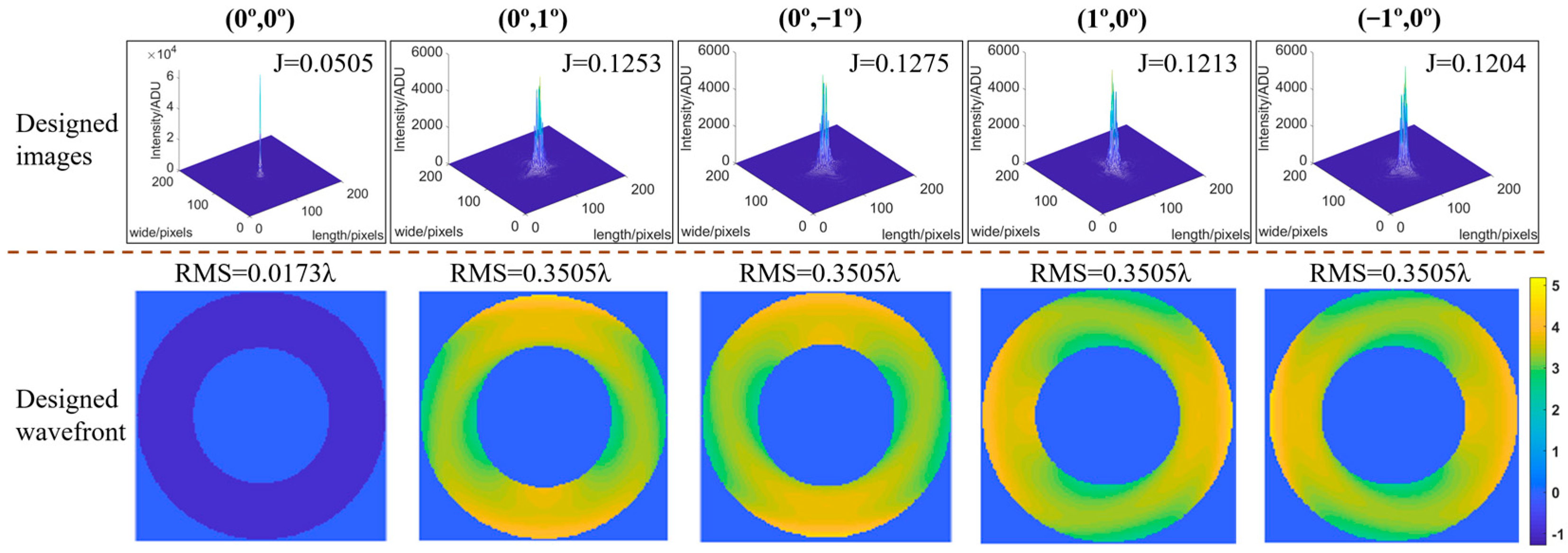
| Designed images | 0.0505 | 0.1253 | 0.1275 | 0.1213 | 0.1204 | 0.1090 |
| Conditions | Fields of View | |||||
|---|---|---|---|---|---|---|
| (0°,0°) | (0°,1°) | (0°,−1°) | (1°,0°) | (−1°,0°) | ||
| Correction 1 | 0.0528 | 0.1263 | 0.1262 | 0.1210 | 0.1222 | 0.1097 |
| Correction 2 | 0.0512 | 0.1287 | 0.1270 | 0.1189 | 0.1250 | 0.1102 |
| Correction 3 | 0.0529 | 0.1260 | 0.1290 | 0.1218 | 0.1217 | 0.1103 |
| Designed images | 0.0505 | 0.1253 | 0.1275 | 0.1213 | 0.1204 | 0.1090 |
Disclaimer/Publisher’s Note: The statements, opinions and data contained in all publications are solely those of the individual author(s) and contributor(s) and not of MDPI and/or the editor(s). MDPI and/or the editor(s) disclaim responsibility for any injury to people or property resulting from any ideas, methods, instructions or products referred to in the content. |
© 2024 by the authors. Licensee MDPI, Basel, Switzerland. This article is an open access article distributed under the terms and conditions of the Creative Commons Attribution (CC BY) license (https://creativecommons.org/licenses/by/4.0/).
Share and Cite
Li, M.; Liu, X.; Zhang, J.; Xian, H. Telescope Alignment Method Using a Modified Stochastic Parallel Gradient Descent Algorithm. Photonics 2024, 11, 993. https://doi.org/10.3390/photonics11110993
Li M, Liu X, Zhang J, Xian H. Telescope Alignment Method Using a Modified Stochastic Parallel Gradient Descent Algorithm. Photonics. 2024; 11(11):993. https://doi.org/10.3390/photonics11110993
Chicago/Turabian StyleLi, Min, Xin Liu, Junbo Zhang, and Hao Xian. 2024. "Telescope Alignment Method Using a Modified Stochastic Parallel Gradient Descent Algorithm" Photonics 11, no. 11: 993. https://doi.org/10.3390/photonics11110993
APA StyleLi, M., Liu, X., Zhang, J., & Xian, H. (2024). Telescope Alignment Method Using a Modified Stochastic Parallel Gradient Descent Algorithm. Photonics, 11(11), 993. https://doi.org/10.3390/photonics11110993