Article

Research on Support Structure of Rectangular Cryogenic Infrared Lens with Large Aperture

1
Changchun Institute of Optics, Fine Mechanics and Physics, Chinese Academy of Sciences, Changchun 130033, China
2
University of Chinese Academy of Sciences, Beijing 10049, China
*
Author to whom correspondence should be addressed.
Photonics 2024, 11(11), 1084; https://doi.org/10.3390/photonics11111084
Submission received: 15 October 2024 / Revised: 14 November 2024 / Accepted: 15 November 2024 / Published: 18 November 2024
(This article belongs to the Section Optoelectronics and Optical Materials)

Abstract

:
This paper presents the design and optimization of a composite flexible support structure aimed at addressing the challenges associated with maintaining the positional accuracy and surface integrity of large-aperture cryogenic infrared lenses with long focal lengths. The primary objective of the structure is to maintain precise lens alignment while preserving the surface shape under operational conditions. The design complexities and underlying principles of the flexible support structure are systematically explored. A mechanical model of the flexible support structure was derived based on its structural characteristics, and the equilibrium equation was established to ensure the lens meets thermal deformation requirements in various directions. Optimization of key design parameters was conducted for a lens operating at 200 K, measuring 304 mm × 230 mm. The gravitational deformation of the optimized lens exhibited a root mean square (RMS) surface accuracy of 7.72 nm in the X direction, 7.08 nm in the Y direction, and 9.60 nm in the Z direction for lens surface 1. For lens surface 2, RMS values were 8.62 nm in the X direction, 8.41 nm in the Y direction, and 9.64 nm in the Z direction. At 200 K and lower temperatures, the RMS values of lens surfaces 1 and 2 were 2.41 nm and 2.74 nm, respectively, with a first-order mode frequency of 143.37 Hz.

1. Introduction

Infrared detection technology, a critical component of space detection systems, finds applications in many fields, including astronomical observation and military target acquisition [1,2,3,4]. To enhance the resolution of space infrared optical systems, large-aperture optical components such as those employed in the American KH-12, GEO-5, and James Webb Space Telescope (JWST) are frequently adopted [5,6,7]. These systems operate in low-temperature environments to reduce background thermal radiation from the opto-mechanical structure, leading to improved detection sensitivity and overall performance [8,9,10,11]. However, the significant temperature differential between the assembly temperature of the optical element and its support structure and the operating environment temperature poses significant challenges in the design of the opto-mechanical structure [12,13].
In recent years, numerous scholars from within China and abroad have investigated lens support mechanisms. Kvamme proposed a flexibly bending support structure for lithium fluoride lenses used in the James Webb Telescope (JWST) [14]. Ge Huanyu, et al. adopted a dual-material support structure designed to compensate for thermal deformation by aligning the cryogenic thermal expansion coefficients of lenses with their thermal deformation, significantly enhancing the force and thermal performance of cryogenic lenses [15]. Zhao Lei, et al. proposed a multi-point uniform support structure with an overall radial flexibility for a 160 mm lens, evenly distributing the gravitational load across each support block through axial flexibility [16]. Zhang Liu, et al. utilized a three-point, six-slit, flexible support structure to mitigate thermal stress between the lens and the lens mount [17]. Wang Xiaodi, et al. proposed a composite flexible support structure for lenses with a 640 mm aperture, employing a design that separated the flexible support from the lens mount to minimize mechanical and thermal influences [18]. These studies primarily focus on support structures for circular lenses.
However, with the increasing weight and volume of space infrared cameras, the design of ultra-lightweight cameras has become a crucial consideration. One effective strategy for achieving large-aperture optics is to reduce the weight of optical components by eliminating excess material. By removing excess material, circular lenses become elongated, making the study of rectangular lens support technology particularly relevant.
In this study, a novel composite flexible support structure for rectangular lenses is presented. A comprehensive mechanical model of the flexible support structure is developed, accounting for thermal deformations of the lens in multiple directions. Equilibrium equations are then established to ensure structural integrity. Subsequently, the flexible support components are optimized, and a thorough analysis is conducted to evaluate the module’s modal performance and surface accuracy under both its own weight and temperature variations.

2. Scheme on Support Structure

2.1. Difficulties in Support Structure Design

Designing support structures for rectangular-aperture lenses in space cameras poses significant challenges.
  • To prevent obstruction of the lens aperture, support points must be positioned at the periphery of the lens. However, in double convex lenses, the pronounced thickness gradient toward the edges results in increased stress at the edges [19].
  • The asymmetry of circular lenses complicates the selection of optimal support locations.
  • Its own weight and thermal loading of the lens can also adversely affect its surface accuracy. Ensuring precise surface accuracy under varying operational conditions requires highly sophisticated support structures [20,21].

2.2. General Structure Design

The representative lens used in this study is a concave–convex lens fabricated from silicon (Si). The lens size is 304 mm × 230 mm, and its clear aperture is 290 mm × 220 mm. Excess material was removed to achieve the required optical aperture, resulting in a significant increase in the length of the lens, as illustrated in Figure 1a. This optimization led to a substantial reduction in lens weight, decreasing from 11.78 kg to 7.19 kg, representing a 39% decrease compared to a circular lens. This reduction offers significant advantages for space cameras, where minimizing weight is crucial. The center of mass position is shown in Figure 1a. Lens position deviation and surface shape deviation requirements of the camera are shown in Table 1.
As illustrated in Figure 1b, the lens assembly comprises a lens, mount, clips, and binder plate. A composite flexure system within the frame consists of three primary flexures and three secondary flexures. The primary flexures feature a flexible structure with fixed end beams and two sets of flexible structures with cantilever steel frames. The secondary flexures are composed of three sets of cantilever-shaped flexible structures. The lens is secured to the frame by the three primary flexures, while the outer edge of the lens is bonded to the three secondary flexures using a structural adhesive. The lens is assembled on the ground in the X direction.
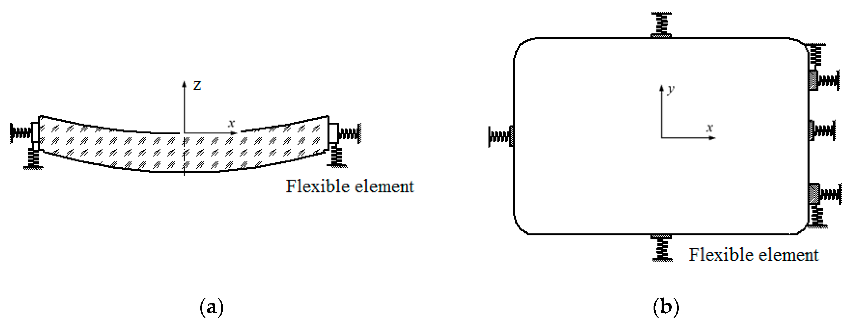
By considering the lens axis as the z-axis and the plane perpendicular to the optical axis as the xy-plane, the structure depicted in Figure 1b can be simplified into the model shown in Figure 2. In this simplified model, a set of flexible structures with fixed end beams and three sets of cantilever-shaped flexible structures can be represented as springs with five degrees of rigidity. Similarly, the two sets of flexible structures with cantilever steel frames can be represented as springs with four degrees of rigidity. The primary function of the support structure is to constrain the six spatial degrees of freedom of the lens, achieving precise positioning and position retention without compromising surface accuracy. As illustrated in Figure 2, the support structure not only effectively positions the lens but also mitigates rigid body displacement in the direction of gravity, enhancing the overall dynamic performance.
The flexible support structure depicted in Figure 2 offers several advantages for rectangular-aperture lenses:
  • The flexible nature of the support structure provides damping, mitigating the impact of shock, vibration, and thermal stress on the lens, thereby preventing excessive internal stresses [22,23,24].
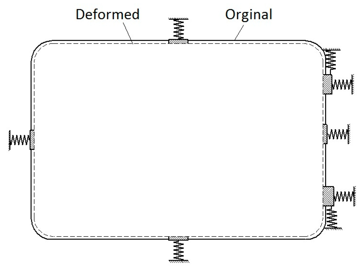
  • As depicted in Figure 3, the radial flexibility of the individual flexures allows the support structure to accommodate inconsistent thermal deformations between the frame and the lens, effectively reducing thermal stress and maintaining the radial position of the lens.
  • The flexible support structure can compensate for any deformations that may occur within the frame itself [25,26].

3. Mechanical Model of the Flexible Support Structure

The composite support structure illustrated in Figure 1b is comprised of three distinct types of flexible support structures. To facilitate the rational design of each individual flexible support structure, a comprehensive analysis of its mechanical model is essential. This analysis will enable the determination of appropriate structural design parameters.

3.1. Flexible Structure in Cantilever Form

As depicted in Figure 4a, the flexibility of the cantilever-shaped flexible structure is attributed to the presence of a flexible chip. Given that both ends of the cantilever-shaped flexible structure are rigidly attached to distinct components, the conventional cantilever beam model is inappropriate for directly analyzing its deformation. A more suitable approach involves employing the half-beam model, which aligns with the deformation characteristics of the structure [27]. Figure 4b,c illustrate the equivalent model and deformation of the cantilever-shaped flexible structure [28].
The deformation along the length direction is very small, so it can be ignored. Additionally, in the half-beam theory [27], Equation (1) is employed to determine the deformation at the movable end of the flexible chip.
u 1 = F l 1 3 E h 1 b 1 3
where E represents the elastic modulus of the flexible chip, l 1 denotes the length of the flexible chip, h 1 signifies the width of the flexible chip, and b 1 represents the thickness of the flexible chip.

3.2. Flexible Structure with Fixed Beams at Both Ends

As depicted in Figure 5a, the flexibility of the structure with fixed beams is attributed to a flexible chip with fixed ends. The equivalent model for this structure, illustrated in Figure 5b, can be simplified into an indeterminate beam exhibiting both lateral and radial rigidity, as shown in Figure 5c [19]. In this simplified model, points O and E represent the fixed ends, while point A denotes the midpoint. The radial deformation u A of point A can be expressed as follows:
u A = l 2   M x E 2 I · M x F D d x = F A E 2 I 0 l 2 2 x 2 l 2 8 d x + F A E 2 I 0 l 2 2 3 l 2 8 x 2 d x = F A l 2 3 192 E 2 I = F A l 2 3 16 E 2 h 2 b 2 3
where E 2 represents the elastic modulus of the flexible chip, I represents moment of inertia, l 2 denotes the length of the flexible chip, h 2 signifies the width of the flexible chip, b 2 represents the thickness of the flexible chip, and FA symbolizes the force exerted at point A.

3.3. Flexible Structures with Cantilever Steel Frame

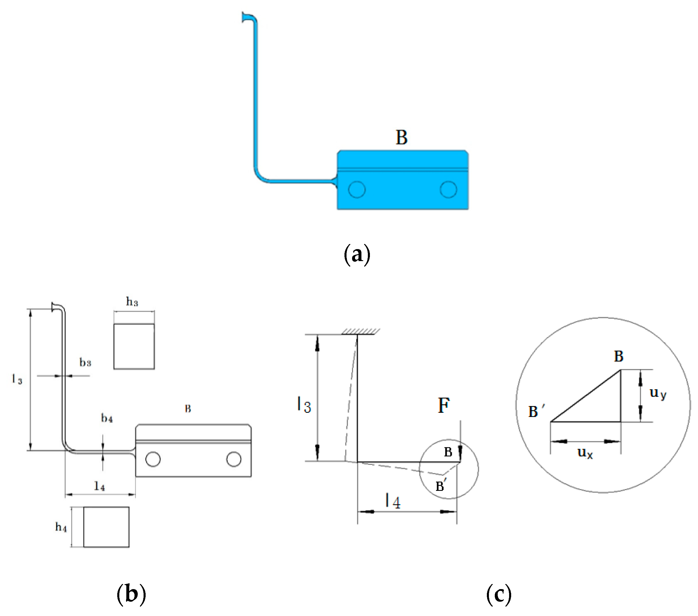
As illustrated in Figure 6a, the flexibility of the flexible structure with a cantilever steel frame is attributed to an L-shaped flexible chip. This structure can be simplified into a statically determinate beam as depicted in Figure 6b based on its structural characteristics. The deformation of this simplified beam is shown in Figure 6c. Deformation may occur at point B, with displacements possible in both the radial u x and transverse u y directions under the influence of a radial force. This deformation pattern aligns with the thermal deformation experienced by the lens mounting point B. The u x and u y deformations at point B can be expressed as follows:
u y = M F M E I d x = ω y c E I = F l 4 × 1 2 l 3 E h 3 b 3 3 12 = 6 F l 4 l 3 E h 3 b 3 3
u x = M F M E I d y = ω y c E I = 1 2 F l 4 × 2 3 l 4 E h 4 b 4 3 12 + F l 4 × 1 2 l 4 E h 3 b 3 3 12 = 4 F l 4 2 E h 4 b 4 3 + 6 F l 4 2 E h 3 b 3 3
where E represents the elastic modulus of the flexible chip, I represents moment of inertia, l 3 and l 4 denote the lengths of the two sections of the flexible chip, h 3 and h 4 signify the widths of the two sections of flexible chip, b 3 and b 4 represent the thickness of the two sections of the flexible chip, and F symbolizes the force exerted at point B.

3.4. Model of the Whole Support Structure

The primary function of the lens support structure is to ensure accurate lens positioning and retention (the position accuracy of the lens) within the permissible deviation range under varying lens weight and temperature fluctuations. For cryogenic lenses, temperature variation is the primary factor affecting position accuracy. Consequently, this study primarily focuses on the positional deviations δ x and δ y of the lens within the plane perpendicular to the optical axis. Figure 7 illustrates the force and displacement characteristics of each supporting unit. The lens is approximated as a rigid body and the equilibrium equations are established with δ x and δ y set to zero.
δ x = u A X + u B X + u C X + u M X = 0
δ y = u D Y + u E Y + u B Y + u C Y = 0
F D + F E = 0
F A + F B + F C + F M = 0
where F A , F B , F C , F D , F E , and F M represent the force exerted on the lens mounting points. u A X , u B X , u C X , and u M X denote the thermal deformation of the lens mounting points in the x-direction. u B Y , u C Y , u D Y , and u E Y denote the thermal deformations of the lens mounting point in the y-direction.
By analyzing Equations (1)–(4), it becomes evident that:
u D Y = u E Y = F D l D 3 E h D b D 3 = B 2 α G E α T C t
u B Y = u C Y = 6 F B l B 4 l B 3 E h B 3 b B 3 3 = B 1 2 α G E α T C t
u A X = F A l A 3 16 E A h A b A 3
u M X = F M l M 3 E h M b M 3 = L 2 α G E α T C t
u B X = u C X = 4 F B l B 4 2 E h B 4 b B 4 3 + 6 F l B 4 2 E h B 3 b B 3 3 = L 2 α G E α T C t

3.5. Optimization Design of Support Structure

The relationships between the parameters of each flexible link within the lens support structure can be derived from the aforementioned equations. Building upon these relationships, the integrated optimization method is used to optimize the flexible support structure [29,30], and the ultimate goal is to find a set of optimal parameters, so that the surface accuracy RMS_X, RMS_Y, RMS_Z, RMS_T of the lens is better than 18.08 nm, and the mode is higher than 100 Hz. The range of each parameter variable can be defined according to the current processing and manufacturing capacity. The optimization model is mathematically described as Equation (14), where the T R 1 represents the values in Table 1.
Figure 8 presents the flow of integrated optimizatin. Specifically, the geometric structure model after manual intervention was established by UG, the finite element analysis model was established by Patran, the deformation of lens and support structure was calculated by Nastran, and the rigid body displacement, inclination Angle, and mirror surface profile changes of the lens were calculated by surface analysis software, and nondomination-based genetic algorithm (NSGA-II) was called to search for the global solution set.
F i n d ( X ) = l n , h n , b n   n = 1 ,   2 ,   3 ,   4 M i n   f m ( RMS X , RMS Y , RMS Z , RMS T ) Min   T R m T x , T y ,   T z , θ x ,   θ y ,   θ z s . t .   1 b n   100 f RMS X 18.08   n m RMS Y 18.08   n m RMS Z 18.08   n m RMS T 18.08   n m   T R m < T R 1
After several iterations, the structural parameters are obtained as shown in Table 2. The optimization results meet the design objectives and consider the processing difficulty of the structure.

4. Simulation Analysis of Lens Sub-Assemblies

4.1. Modal Analysis

During transportation and launching, the lens sub-assemblies are subjected to various mechanical factors, including vibration, shock, noise, and other mechanical influences [31,32]. To ensure structural integrity and safety, these sub-assemblies must exhibit sufficient rigidity and strength. Modal analysis is conducted to evaluate the dynamic characteristics of the lens sub-assemblies. The material properties of the sub-assemblies are depicted in Table 3 and the first three mode shapes and frequencies are depicted in Table 4 and Figure 9.

4.2. Surface Shape and Rigid Body Displacement Analysis

Considering the external connection point of the lens sub-assemblies as the constrained boundary, the changes in surface shape and rigid body displacement of the lens under the influence of its own weight are illustrated in Table 5 and Figure 10 and Figure 11. We can see from the figure that the gravitational deformation of the lens top—lens surface 2—is an astigmatis. But it is far less than the required value of optical design, so it is also a desirable result. Similarly, the changes in surface shape and rigid body displacement resulting from temperature loading are depicted in Table 6 and Figure 12. The deformation pattern does not follow the support positions. This is because the maximum deformation is very small, and this correspondence is not obvious. As shown in Figure 13, the asymmetric pattern can be reproduced by changing the size of the finite element.

5. Discussion

The results show that the composite flexible support structure explored in this paper not only guarantees the surface shape accuracy and position accuracy of the lens, but also has a high fundamental frequency of the component. The cantilever steel frame flexible element solves the problem that the support structure has bidirectional flexibility in the radial direction of the lens (X0Y plane). The mechanical model of flexible support structure and thermal deformation equilibrium equation can guide the design and optimization of support structure.
The prior studies focused on the support mode of circular aperture lenses. Kvamme proposed a flexibly bending support structure for lithium fluoride lenses [8]. Ge Huanyu, et al. adopted a dual-material support structure designed to compensate for thermal deformation by aligning the cryogenic thermal expansion coefficients of lenses with their thermal deformation [9]. Wang Xiaodi, et al. proposed a composite flexible support structure for lenses with a 640 mm aperture, employing a design that separated the flexible support [12]. Consistent with the prior studies, our study on the support structure of rectangular aperture lenses can realize the lightweight design of a lens, which is very beneficial to reducing the weight and volume of space infrared cameras.
This paper demonstrated the capability of the lens support scheme and theoretical analysis process for the design of a large aperture strip lens support structure, which can be one of the effective measures for the lightweight design of space cameras. The results of a lens with a size of 304 mm × 230 mm show that the weight is reduced by 39% compared with the circular diameter, the maximum deformation (RMS) of the lens under its own weight is 9.64 nm, the maximum deformation (RMS) at low temperature of 200 k is 2.74 nm, and the first mode is 143.37 Hz.
Research on the support structure of rectangular aperture lenses belongs to the forefront of the industry. In the future, the global optimization of flexible structure size and the combination of flexible structures can be explored, along with the alignment of the lens and the flexible support structure, and the centering alignment between multiple rectangular cryogenic lens components.

Author Contributions

Conceptualization, M.S.; methodology, M.S. and H.Q.; software, M.S. and X.P.; formal analysis, M.S.; writing—review and editing, Y.L.; funding acquisition, J.G.; other works, M.S. All authors have read and agreed to the published version of the manuscript.

Funding

This research was funded by CIOMP grant number “CIOMP210C”.

Institutional Review Board Statement

Not applicable.

Informed Consent Statement

Not applicable.

Data Availability Statement

Data underlying the results presented in this paper are not publicly available at this time but may be obtained from the authors upon reasonable request.

Conflicts of Interest

The authors declare no conflicts of interest.

References

  1. Huang, C.; Wang, J.; Xue, L.; Zhao, L. Next Generation of Astronomical Telescope and Survey Mission (I). Infrared Laser Eng. 2016, 45, 204–208. [Google Scholar]
  2. Huang, C.; Wang, J.; Xue, L.; Zhao, L. Next Generation of Astronomical Telescope and Survey Mission (II). Infrared Laser Eng. 2016, 45, 170–175. [Google Scholar]
  3. Pan, C.; Cang, L.; Luo, M.; Tao, L.; Chen, S.; Chen, B.; Bai, Z.; Cui, H.; Xu, C.; Zhao, J. Development Status and Application of Space Infrared Camera Optical Technology. Infrared Technol. 2022, 44, 1186–1193. [Google Scholar]
  4. Fu, L.; Xu, S.; Jiao, T.; Du, K. Development Status and Trend of Space Optical Loading. In Proceedings of the 2015 Infrared and Remote Sensing Technology and Application Symposium and Interdisciplinary Forum, Barcelona, Spain, 19–24 April 2015; pp. 1–10. [Google Scholar]
  5. Global Security. SBIRS GEO—Geostationary Earth Orbit [EB/OL]. Available online: http://www.globalsecurity.org/space/systems/sbirs-geo.html (accessed on 25 October 2022).
  6. Zhang, J. Lockheed Martin Aerospace Development Research in 2020; Aerospace China: Jingjiang, China, 2021; Volume 1, pp. 20–30. [Google Scholar]
  7. Kvamme, E.T.; Trevias, D.; Simonson, R. A Low Stress Cryogenic Mount for Space-borne Lithium Fluoride Optics. SPIE 2005, 5877, 276–286. [Google Scholar]
  8. Chen, G.; Shi, G.; Wu, F.; Wang, J.; Pei, L.; Shi, G. Analysis of thermal optical properties for a thermal infrared lens. Laser Infrared 2017, 47, 1299–1304. (In Chinese) [Google Scholar]
  9. Wang, Z.; Liang, J.; Zhao, M.; Chen, H.; Wang, J.; Wei, L. Lens mount for cryogenic refractive optics cooled by mechanical cryo-cooler. Infrared Laser Eng. 2019, 48, 0218006. [Google Scholar] [CrossRef]
  10. Li, J.; Li, Z.; Liu, J.; Zhang, L.; Liu, X. Analysis and suppression of external stray light in spatial infrared detection system. Laser Infrared 2015, 45, 185–188. [Google Scholar]
  11. Yu, X. Simulation Analysis of Spurious Radiation Transmission Characteristics of Infrared Detection System and Its Environment; Harbin Institute of Technology: Harbin, China, 2015. [Google Scholar]
  12. Gao, Y.; Zhang, B. Design and analysis for the flexible support structure of high precision lens assembly. Optik 2018, 175, 228–236. [Google Scholar] [CrossRef]
  13. Gao, Y.; Li, F.; Shen, Z.; Ding, L.; Hu, B.; Xu, S. Simulation method and its test verification of cryogenic infrared lens design. Infrared Laser Eng. 2021, 50, 20200397. [Google Scholar]
  14. Kvamme, E.T.; Jacoby, M.; Osborne, L. Opto-mechanical Test Results for the Near Infra-red Camera on the James Webb Space Telescope. In Space Telescopes and Instrumentation 2008: Optical, Infrared, and Millimeter; SPIE: Bellingham, WA, USA, 2008; Volume 7010, pp. 310–321. [Google Scholar]
  15. Ge, H.; Xiao, Z.; Wang, Y. Research on Cryogenic Lens Support Structures Based on a Bi-material System for Thermal Deformation Compensation. Spacecr. Recovery Remote Sens. 2022, 43, 69–75. (In Chinese) [Google Scholar]
  16. Zhao, L.; Peng, H.; Yu, X. Lens Support Structure of Multi-points Equal Supporting with Wholly Radical Freedom. Opto-Electron. Eng. 2015, 42, 43–48. (In Chinese) [Google Scholar]
  17. Zhang, L.; Zhang, X.; Zhang, F. Structural Optimization Design of Large Tolerance and Multi-flexibility Lens Sub-assembly. J. Jilin Univ. (Eng. Technol. Ed.) 2021, 51, 478–485. (In Chinese) [Google Scholar]
  18. Wang, X.; Cao, Y.; Wang, F.; Chu, H.; Li, Y. Optimization Design of Large-aperture Lens Mixed Flexible Support Structure. Infrared Laser Eng. 2022, 51, 1–7. [Google Scholar]
  19. Cao, Y.Y.; Wang, J.L.; Chu, H.L.; Li, H.W.; Chen, T.; Ming, M.; Jiang, F. Design and Analysis of Bi-flexible Mounting Structure for Large Optical Lens. Opt. Precis. Eng. 2021, 29, 1868–1879. [Google Scholar] [CrossRef]
  20. Wittrick, W.H. The properties of crossed flexure pivots, and the influence of the point at which the strips cross. Aeronaut. Q. 2016, 2, 272–292. [Google Scholar] [CrossRef]
  21. Chen, X.; Li, Z.; Jin, G. Dimensionless design model for biaxial Cart wheel flexure hinges. Mech. Based Des. Struct. Mach. 2018, 46, 401–409. [Google Scholar]
  22. Cao, Y.Y.; Wang, Z.C.; Zhou, C.; Fan, L.; Han, X.D.; Zhang, Y.Z. General modeling and optimal design of flexure sup-porting structure for optical components. Opt. Precis. Eng. 2016, 24, 2792–2803. (In Chinese) [Google Scholar] [CrossRef]
  23. Cao, Y.; Wang, Z.C.; Zhou, C. Modeling and optimal design of circular-arch flexible structure with radial freedom considering geometry and material selection simultaneously. Precis. Eng. 2017, 48, 83–97. [Google Scholar] [CrossRef]
  24. Wang, C.; Hu, Z.; Chen, Y.; Xu, M.; Chen, L. Structural design optimization of space gravitational wave telescope primary mirror system. Infrared Laser Eng. 2020, 49, 20190469. (In Chinese) [Google Scholar] [CrossRef]
  25. Qu, H.; Wei, J.; Dong, D.; Hu, H.; Guan, Y. Lightweight structural design of rectangular space mirror assembly. Infrared Laser Eng. 2021, 50, 20200404. (In Chinese) [Google Scholar]
  26. Karim, T.; Lee, J.H.; Eisenstein, D.J.; Burtin, E.; Moustakas, J.; Raichoor, A.; Yèche, C. Validation of emission-line galaxies target selection algorithms for the dark energy spectroscopic instrument using the MMT binospec. Mon. Not. R. Astron. Soc. 2020, 497, 4587–4601. [Google Scholar] [CrossRef]
  27. Cao, D.; Gao, Y. Error Analysis of Precise Non-guiding Displacement Platform. Opt. Precis. Eng. 2012, 20, 313–321. [Google Scholar]
  28. Ma, L.; Cao, D.; Liu, C. Design and Analysis on Multi-points Flexible Support Structure of Large-aperture Lens. Opto-Electron. Eng. 2015, 42, 88–93. [Google Scholar]
  29. Wang, Z.; Zhang, J.; Wang, J.; He, X.; Fu, L.; Tian, F.; Liu, X.; Zhao, Y. A Back Propagation neural network based optimizing model of space-based large mirror structure. Optik 2019, 179, 780–786. [Google Scholar] [CrossRef]
  30. Wang, H.; Guo, J.; Shao, M.; Sun, J.; Tian, F.; Yang, X. Optimization design of an ultralight large-aperture space mirror. Appl. Opt. 2021, 60, 10878–10883. [Google Scholar] [CrossRef]
  31. Ke, S. Satellite Environment Engineering and Simulation Experiment (2); China Aatronautic Publishing House: Beijing, China, 2005; pp. 23–31. (In Chinese) [Google Scholar]
  32. Song, J.; Xing, H.; Pei, J.; Yang, T.; Mu, S. Measurement and error analysis of encircled energy of cryogenic lens. Infrared Laser Eng. 2019, 48, 0717007. (In Chinese) [Google Scholar] [CrossRef]
Figure 1. Lens and support structure: (a) Lens shape and dimension parameters; (b) Lens support structure. Lens dimensions include the overall dimensions of the lens, the spherical radius of the mirror surface, and the central thickness of the lens.
Photonics 11 01084 g001
Figure 2. Principle of the support structure: (a) Front view; (b) Top view.
Photonics 11 01084 g002
Figure 3. Thermal adaptability of the flexible support structure. The dotted line indicates the lens shape after thermal deformation.
Photonics 11 01084 g003
Figure 4. Flexible structure, equivalent model, and schematic deformation: (a) Structure of the cantilever flexible structure; (b) Equivalent model; (c) Schematic deformation.
Photonics 11 01084 g004
Figure 5. Radial flexible support structure, equivalent model, and equivalent statically determinate model: (a) Radial flexible support structure; (b) Equivalent model; (c) Equivalent statically determinate model.
Photonics 11 01084 g005
Figure 6. Flexible structure, equivalent model, and Schematic deformation: (a) Flexible structure with cantilever steel frame; (b) Equivalent model; (c) Schematic deformation.
Photonics 11 01084 g006
Figure 7. Analysis of the force and displacement of the whole structure in xy direction.
Photonics 11 01084 g007
Figure 8. The Flow chart of integrated optimization.
Photonics 11 01084 g008
Figure 9. The first three mode shapes of the lens sub-assemblies: (a) The 1st mode shape; (b) The 2nd mode shape; (c) The 3rd mode shape. The colors in the figure indicate the values of the amplitude at each part. The brighter the color, the larger the absolute value.
Photonics 11 01084 g009
Figure 10. Deformation contours of lens top—lens surface 1—under its own weight: (a) Deformation under Grav_X; (b) Deformation under Grav_Y; (c) Deformation under Grav_Z. The colors in the graph indicate the values of the deformation at each part. Red means positive and blue means negative, and the brighter the color, the larger the absolute value.
Photonics 11 01084 g010
Figure 11. Deformation contours of lens top—lens surface 2—under its own weight: (a) Deformation under Grav_X; (b) Deformation under Grav_Y; (c) Deformation under Grav_Z. The colors in the graph indicate the values of the deformation at each part. Red means positive and blue means negative, and the brighter the color, the larger the absolute value.
Photonics 11 01084 g011
Figure 12. Deformation contours of lens top surface under temperature load: (a) Deformation contours of face1; (b) Deformation contours of face2. The colors in the graph indicate the values of the deformation at each part. Red means positive and blue means negative, and the brighter the color, the larger the absolute value.
Photonics 11 01084 g012
Figure 13. The finite element and deformation map of lens top surface under temperature load: (a) Sparse mesh and deformation map; (b) Dense mesh and deformation diagram.
Photonics 11 01084 g013
Table 1. Lens position deviation and surface shape deviation requirements.
FaceTran_x
(μm)
Tran_y
(μm)
Rotation_x
(″)
Rotation_y
(″)
RMS (nm)
Face1 3030202018.08
Face23030202018.08
Table 2. Optimization results of flexure hinge support structure.
Supports Positionln/mmhn/mmbn/mm
A (n = 2)40.034.02.0
D,E (n = 1)35.030.01.0
B,C (n = 3)35.034.02.0
B,C (n = 4)28.034.02.0
M (n = 1)40.030.01.0
Table 3. Material parameters.
MaterialsDensity
ρ (g/cm3)
Elastic Modulus
E (GPa)
Poisson’s RatioThermal Expansion Coefficient
α (10−6/°C)
Si2.3313.10.264.15
TC44.4410.90.349.1
Table 4. Modal analysis results of lens sub-assembly.
OrderFrequency/HzMode Shapes
1143.37Move along Z-axis
2189.69Move along Y-axis
3200.42Move along X-axis
Table 5. Surface shape and rigid body displacements of the lens under its own weight.
Load CaseFaceTran_x
(μm)
Tran_y
(μm)
Rotation_x
(″)
Rotation_y
(″)
Rotation_z
(″)
PV
(nm)
RMS (nm)
Grav_YFace1 0.576.51.52−1.080.2329.347.08
Face20.576.41.52−1.070.3930.528.41
Grav_XFace1 7.01−0.028−1.121.05−0.00132.467.72
Face27.02−0.28−1.111.060.2936.568.62
Grav_ZFace1 0.76−0.43−0.070.27−0.1140.039.60
Face20.57−0.350.1−0.070.2340.959.64
Table 6. Surface shape and rigid body displacements of the lens sub-assemblies under temperature load.
Load CaseFaceTran_x
(μm)
Tran_y
(μm)
Rotation_x
(″)
Rotation_y
(″)
Rotation_z
(″)
PV
(nm)
RMS (nm)
200kFace1 0.32.6−1.310.620.7712.472.41
Face2−0.11.7−2.111.051.4112.962.74
Disclaimer/Publisher’s Note: The statements, opinions and data contained in all publications are solely those of the individual author(s) and contributor(s) and not of MDPI and/or the editor(s). MDPI and/or the editor(s) disclaim responsibility for any injury to people or property resulting from any ideas, methods, instructions or products referred to in the content.