Article

Reduction in Temperature-Dependent Fiber-Optic Gyroscope Bias Drift by Using Multifunctional Integrated Optical Chip Fabricated on Pre-Annealed LiNbO3

1
Nanotechnology Research Center, Bilkent University, Ankara 06800, Turkey
2
Department of Nanotechnology and Nanomedicine, Hacettepe University, Ankara 06800, Turkey
3
Department of Physics, Bilkent University, Ankara 06800, Turkey
4
Department of Electrical and Electronics Engineering, Bilkent University, Ankara 06800, Turkey
5
CW Enerji Müh. Tic. ve San. A.Ş., Antalya 07070, Turkey
*
Author to whom correspondence should be addressed.
Photonics 2024, 11(11), 1057; https://doi.org/10.3390/photonics11111057
Submission received: 10 October 2024 / Revised: 7 November 2024 / Accepted: 8 November 2024 / Published: 11 November 2024
(This article belongs to the Section Optoelectronics and Optical Materials)

Abstract

:
The refractive index change obtained after annealed proton exchange (APE) in lithium niobate (LiNbO3) crystals depends on both the proton exchange process carried out in hot acid and the structure of the crystals. In devices produced by the APE method, dislocations and lattice defects within the crystal structure are considered to be primary contributors to refractive index discontinuities and waveguide instability. In this study, the effects of pre-annealing LiNbO3 crystals at 500 °C on multifunctional integrated optical chips (MIOCs) were investigated through interferometric fiber-optic gyroscope (IFOG) system-level tests. It was observed that the pre-annealing process resulted in an improvement in the optical throughput of MIOCs (from %34 to %51) and the temperature-dependent bias drift stability of the IFOG (from 0.031–0.038°/h to 0.012–0.019°/h). The angle random walk (ARW) was measured as 0.0056 deg/√h.

1. Introduction

Gyroscopes are angular rotation sensors that have a wide range of applications, including space exploration, aviation, international travel, as well as military and industrial uses [1]. Several competing gyroscope technologies have been developed, mainly due to the need to meet application-specific performance metric grades, lower costs, and related to the ease and readiness of technological availability. Hemispherical resonator gyroscopes (HRGs) are stable, solid-state mechanical systems that offer superior size, weight and power (SWAP) characteristics that make them better suited for space, advanced inertial navigation, and other SWAP-sensitive applications. The disadvantage of HRGs is that the manufacturing process is relatively costly, complex, and the technology is not readily available for mass production, except by a few companies [2]. In contrast, optical methods use the phase shift created in a rotating light wave path for sensing rotation. A prevalent optical technology, particularly preferred in military grade systems, is the ring laser gyroscope (RLG), which is prone to the lock-in effect and, hence, requires complex compensating mechanisms and moving parts [3,4,5]. One particularly successful method for constructing a gyroscope is IFOG, whose operation is based on the Sagnac principle, that is, the direct measurement of the phase difference between two counter-propagating waves traveling through a fiber coil. IFOGs demonstrate superior controllability in regard to their manufacturability and can be easily adapted to meet various operational requirements, by altering the length of the fiber and the diameter of the loop, resulting in adjustable resolution and range. This adaptability, combined with their higher resolution and precision, positions IFOGs as the preferred choice over RLGs [1,6]. Because of these characteristics, IFOGs have typically seen broader use in industrial and military sectors compared to RLGs [7]. In addition, IFOGs offer a solid-state, low-power, lightweight solution that can withstand high g-forces and radiation, making them suitable for deployment in extreme conditions, including military applications [7,8]. A miniaturized version of IFOG is also actively used in space applications [9]. Research is underway towards reducing the size of optical gyroscopes to the point where they can be included in consumer electronics and other low-cost, low-sensitivity systems. Micro-fabricated integrated optical components can replace some portion of the optical routing path [10], or in other instances, such as the resonant micro-optic gyroscope (RMOG), the complete gyroscope structure can be created on a monolithic substrate [11]. Such miniaturized systems, although promising for future breakthroughs in regard to the system size and cost, currently lack the required sensitivity for deployment in major navigation-grade applications, similar to the sensitivity limit observed in micro-electro-mechanical systems (MEMS) gyroscopes [11]. There are various types of MEMS gyroscopes, including vibrating structure, tuning fork, and Coriolis vibratory gyroscopes. The advantages include their compact size, low-power consumption, and cost effectiveness, making them suitable for mobile devices [12] and automotive applications [13]. However, they generally have lower accuracy and sensitivity than optical gyroscopes [14] and their performance can be affected by temperature and environmental vibrations [15]. With advancements in photonic integration, there is growing interest in developing chip-scale optical gyroscopes. Recently, ring lasers on silicon chips have enabled the demonstration of gyroscopes capable of detecting Earth’s rotation, marking a significant achievement in this new class of miniaturized, highly sensitive gyroscopes [16]. While these chip-scale optical gyroscopes show promise due to their integration potential and robustness, they currently achieve sensitivity levels sufficient only for detecting Earth’s rotation. Additionally, a recent demonstration of an acousto-optic gyroscope (AOG) on thin-film lithium niobate shows the potential for micromachined, strain-based gyroscopes that leverage the acousto-optic effect, rather than conventional displacement sensing. This approach combines acoustic and photonic components, paving the way for a new class of compact gyroscopes that integrate the benefits of optical and microscale vibrating gyroscopes [17]. Another version of the fiber-optic gyroscope based on the Sagnac effect is the resonator fiber-optic gyroscope (RFOG), which relies on frequency measurements of a laser resonator [18]. While both types initially had similar expectations in regard to their theoretical performance, IFOG-based inertial measurement units have been used in many industrial and military applications that are actively working worldwide [7,19]. In contrast, the RFOG remains in the laboratory stage [20,21], primarily because it struggles with stability and sensitivity issues. Factors such as resonance linewidth broadening, vulnerability to environmental noise, and the complexity of precise laser frequency control, have limited its practical deployment [22,23]. Furthermore, the IFOG is conveniently located in regards to the sensitivity vs. availability/cost trade-off, hence it offers several advantages, such as high performance, high sensitivity, and cost effectiveness, simultaneously [24].
IFOG configurations can be established as either open-loop or closed-loop systems [6]. Open-loop IFOGs are typically used in low-cost applications that do not require high sensitivity [25]. Closed-loop IFOG configurations are used to enhance the performance and accuracy of the gyroscope [26]. In a closed-loop IFOG configuration, a MIOC is used to perform the functions of single-mode optical waveguide, phase modulation, polarization of light, splitting of the light directed towards the coil, and recombining the returning light from the coil [27]. LiNbO3 crystals are widely used in the production of phase and amplitude modulators, including MIOCs, due to its suitability for low-loss waveguide fabrication through various techniques, its high electro-optic coefficient, and its high Curie temperature [28]. The two primary fabrication methods used for waveguide production on LiNbO3 crystals are the annealed proton exchange (APE) method [29] and the titanium metal diffusion method [30]. The APE method is highlighted in the literature for its high performance in polarization applications [31], as it increases the extraordinary refractive index of the birefringent LiNbO3 crystal while reducing the ordinary refractive index [32]. The refractive index change obtained after APE depends on both the proton exchange process carried out in hot acid and the structure of the crystal [33]. Dislocations and lattice defects in the surface-level structure of LiNbO3 crystals, lead to refractive index variations and waveguide instability of devices produced by the APE method [34]. Previous studies in the literature have shown that the density of the dislocations and surface defects of the LiNbO3 crystal can be reduced through pre-annealing [35] and the modulator performance can be improved [36]. In the present study, the effects of the pre-annealing of LiNbO3 crystals at 500 °C on MIOCs were investigated through IFOG system-level tests. The target application for the sensitivity grade of the system used to test the MIOC performance is the inertial navigation grade, typically with an ARW in the order of 0.005 deg/√h.

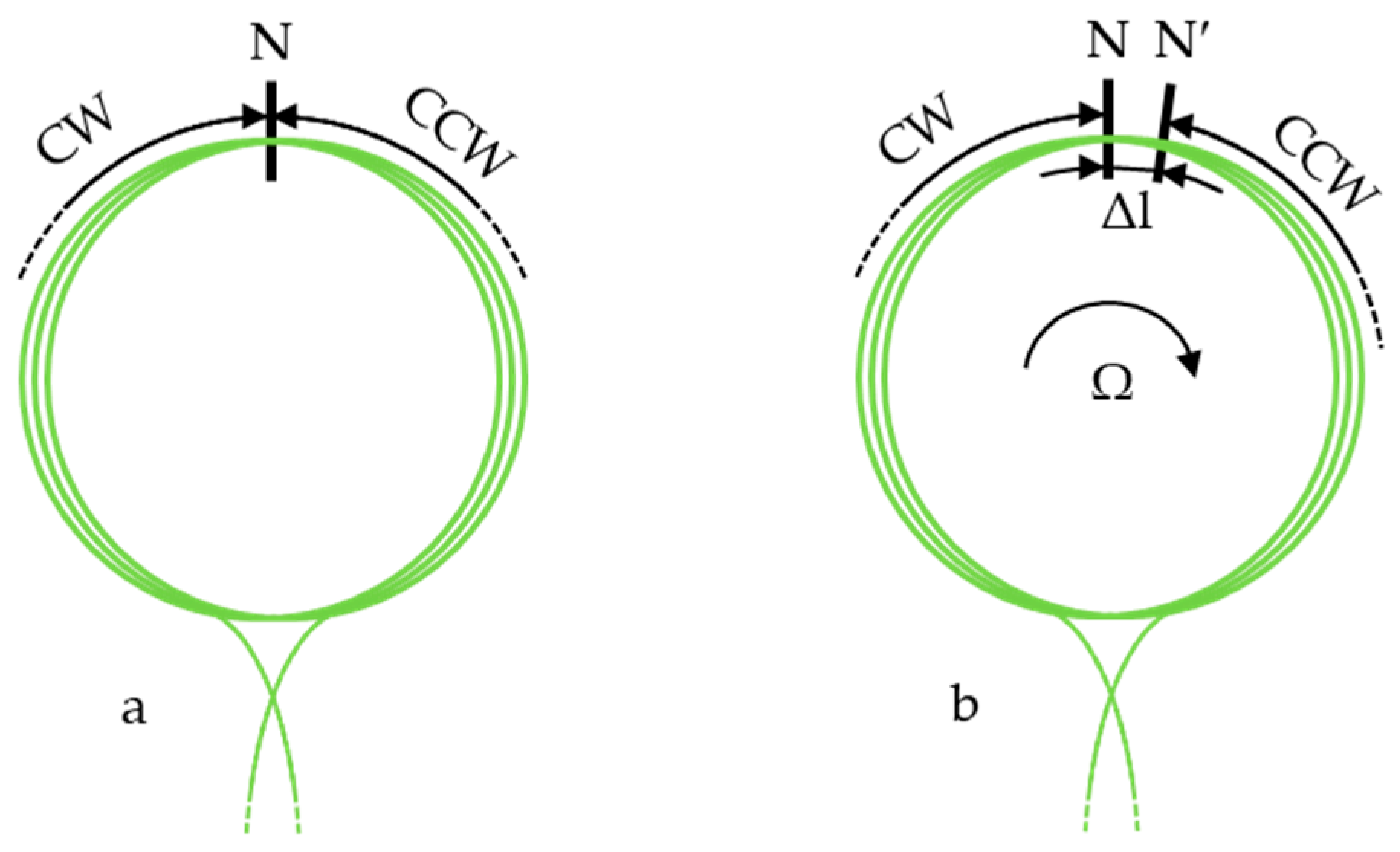
1.1. Interferometric Fiber-Optic Gyroscopes

IFOGs, which are based on the Sagnac principle, directly measure the phase difference between two waves propagating through fiber-optic cables in a fiber coil. The Sagnac effect is typically based on the interference of light waves in a closed-loop system, usually provided by a ring interferometer. When a coherent light source is split into two counter-propagating beams and circulated along a closed path, the rotation of the system creates a phase difference between the beams (Figure 1). According to the Sagnac effect, the optical signal moving in the direction opposite to the rotation travels a shorter path, while the signal moving in the direction of rotation covers a longer path. The resulting phase difference is used to determine the angle of rotation [6]. This phase difference, which is proportional to the angular velocity of the rotation, is detected and used in IFOGs for precise measurements [37]. As a result, an observable interference pattern emerges, illustrating the phase shift caused by the rotations.
A basic IFOG configuration includes a light source, a beam splitter, a fiber-optic coil forming a closed-loop system, and photodetectors to capture the interference pattern. The optical signal emitted from the light source is split in two via a beam splitter. The light exiting the beam splitter propagates through the fiber ends of the fiber coil, traveling in opposite directions along the fiber coil. After completing one round trip through the fiber coil, both light beams recombine at the beam splitter and the interference between the counter-propagated beams is detected at the photodetector. In an open-loop IFOG configuration, a piezo-electric transducer (PZT) phase modulator is commonly placed at the end of the fiber coil for phase modulation. To achieve a linear output at high rotation rates, a MIOC-based closed-loop IFOG configuration can be used. In a closed-loop configuration, the modulated signal, which is polarized, is sent back to a phase shifter to compensate for the induced Sagnac phase shift. This method maintains the interferometer operating point at the desired bias setting, typically where sensitivity is maximized, and the system’s feedback signal reflects the rotation rate. When the feedback signal is directly proportional to the phase shift, a linear output response of the rotation rate is achieved [38].
Traditional IFOG configurations without the MIOC may encounter limitations in terms of signal modulation, demodulation, and data extraction. By applying a systematic modulation scheme to the light waves, the MIOC overcomes these challenges and enables more efficient extraction of the phase information from the interferometric signals. This modulation process significantly improves the sensitivity and precision of the IFOG, resulting in a substantial enhancement to the gyroscope’s fundamental configuration [39]. IFOG performance parameters, such as the bias error, ARW, and scale factor stability, are critical in defining the precision and reliability of the sensor in respective applications across fields that require highly accurate angular velocity measurements [40]. Bias error represents the deviation between the measured output and the true angular rate in the absence of rotation. It is influenced by imperfections in the gyroscope’s components and environmental conditions, necessitating careful design optimization and compensation techniques to minimize its impact on measurement accuracy [41]. The ARW characterizes the random fluctuations in the output of a fiber-optic gyroscope, while measuring a constant angular rate. It quantifies the inherent noise produced by the system, reflecting how much the output signal will vary over time under stable input conditions. A lower ARW value is crucial as it indicates enhanced measurement consistency, stability, and precision, over extended periods. Factors affecting the ARW include the quality of the optical components, the design of the fiber winding, and the implementation of control mechanisms within the gyroscope [42]. The ARW performance in IFOGs can be significantly enhanced through improvements in the performance of the MIOC. The MIOC plays a crucial role in controlling the characteristics of the light through an IFOG, reducing the phase noise and cross-polarization-related noise associated with the light waves traveling through the fiber coil, leading to a lower ARW value [43]. Scale factor stability reflects the gyroscope’s ability to provide consistent precision over time. It measures the output deviations related to specific angular rate inputs, with stable scale factors being crucial for accurate measurements. Variations in temperature and mechanical stress can affect the scale factor stability, which can be enhanced through rigorous calibration and the careful selection of materials [44]. Drift in IFOGs critically impacts sensitivity. Environmental factors, particularly temperature fluctuations, introduce phase noise and bias instability, destabilizing the gyroscope’s scale factor, which is essential for maintaining high sensitivity in precise angular velocity measurements. Studies have shown that the scale factor stability is vital for minimizing sensor errors, where reductions in bias drift contribute to greater measurement accuracy by sustaining sensitivity over time [1,45]. Furthermore, implementing thermal control and advanced bias modulation techniques, such as multi-harmonic modulation, can reduce phase noise and random walk levels, thus preserving the gyroscope’s effective sensitivity and bandwidth by keeping noise floor and drift effects low [46]. DC bias drift is a well-known phenomenon in LiNbO3 modulators, which becomes a significant error source, especially under varying temperature conditions [47]. Although the MIOC provides a convenient solution to signal improvement in IFOGs, it may become an error source itself through MIOC modulator bias drift. In this paper, we demonstrate that the detrimental effects of MIOC-based bias drift can be reduced by employing the pre-annealing process, described below, prior to MIOC fabrication.

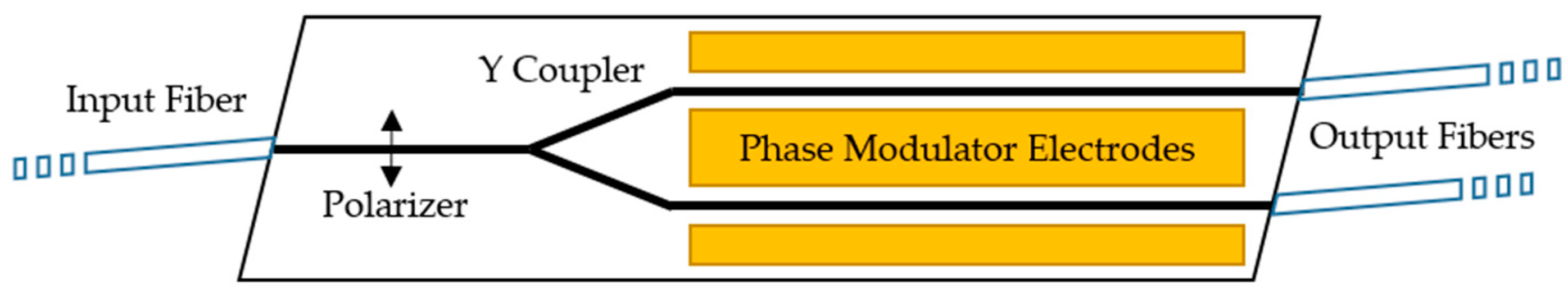
1.2. Multifunctional Integrated Optical Chip

The MIOC [26] device fabricated on LiNbO3 is an electro-optic modulator, specifically designed for closed-loop IFOG applications, encompassing several key functionalities, including a single-mode Y-shaped waveguide acting as a beam splitter, a broadband phase modulator, and a polarizer. The LiNbO3 MIOC has a high modulation bandwidth, enabling the execution of multi-harmonic signal modulation for various closed-loop signal-processing schemes [31].
To form the waveguide structure on a lithium niobate crystal, buried channel waveguides are needed. Conventionally, to create these regions, titanium diffusion [30] or proton exchange [29] processes are applied to areas patterned as waveguides through photolithography. Using these methods, different ions are doped into the lithium niobate crystal to increase the refractive index of the material, resulting in a structure with the desired index profile for a single-mode waveguide, with a well-matched mode shape to the fiber coil mode shape.
A conceptual drawing of the MIOC is provided in Figure 2. The areas shown with thick black lines represent the waveguides. The Y coupler splits the light into two arms and recombines the light from the two arms into a single arm. By using phase modulator electrodes, an electric field can be applied to the waveguide structures, thereby modulating the phase of the light propagating in the waveguide exposed to the electric field through the electro-optic effect in lithium niobate [48]. Polarizing waveguides decrease polarization related non-reciprocity [49], performing an important function for fiber-optic gyroscopes. Very high polarization extinction ratio polarizers can be obtained when the waveguide is formed by the APE method [50,51]. As shown in Figure 2, optical pigtailing between fiber-optic cables and the MIOC device is required for system-level integration with the IFOG. The fiber-optic cable–waveguide interface is joined at a specific angle to prevent back reflections [18].

2. Fabrication, Test, and Results

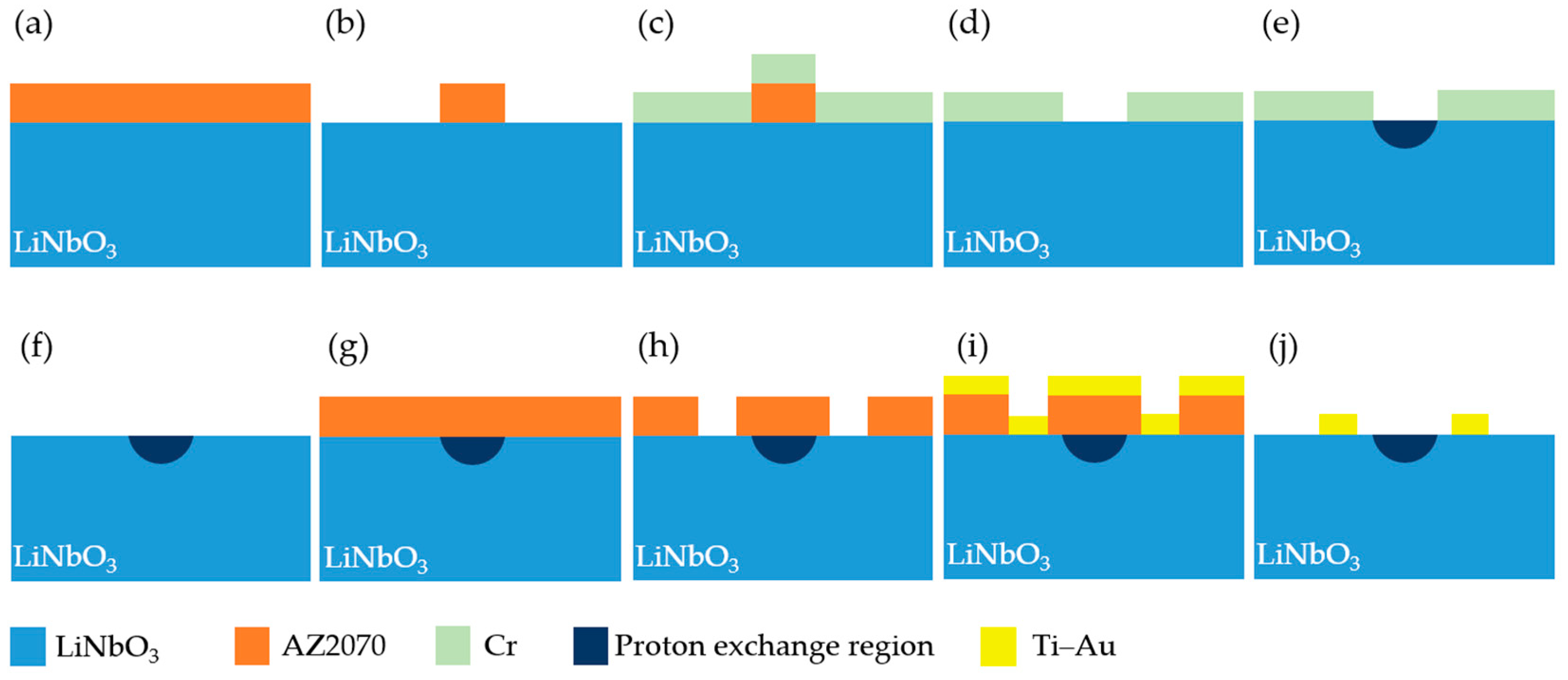
2.1. MIOC Fabrication

MIOC devices were fabricated using x-cut LiNbO3 wafers (manufactured by Del Mar Photonics Inc., San Diego, CA, USA). A total of eight wafers were fabricated. While four wafers underwent a pre-annealing process, the other four were used without any modification. For both types of wafers, our standard MIOC design and fabrication recipe was used, the details of which can be found in our previous works [52,53,54,55]. The only difference in the MIOC fabrication recipe was the pre-annealing step employed for half of the wafers. The pre-annealing process was conducted in a quartz tube placed inside a three-zone furnace. The furnace was heated from room temperature to 500 °C at a rate of 5 °C/min and held at this temperature for 3 h, before being cooled back to room temperature. All eight wafers were produced using the same fabrication recipe. For the waveguide fabrication, AZ2070 (MicroChemicals GmbH, Ulm, Germany) photoresist was spin coated onto the wafers and, using a waveguide mask, the wafers were exposed to UV light with a Karl Süss MA6 photolithography device. After the development process, the samples were coated with 60 nm of Ti using an e-beam evaporator. Following the lift-off process, the proton exchange process was carried out in benzoic acid at 175 °C for 2 h. After proton exchange, the Ti coating was wet etched. The wafers were then annealed at 380 °C, using a controlled annealing process, with the annealing time adjusted to ensure that the refractive index change for each wafer followed the same profile, as detailed in [52]. The refractive index change measurements were performed using a Metricon 2010/M prism coupler device. For the electrode fabrication, a process similar to the waveguide fabrication was followed: AZ2070 photoresist was spin coated onto the wafers, aligned with an electrode mask, and exposed to UV light. After the development process, 10 nm Ti (for the adhesion layer) and 250 nm Au (electrode layer) were deposited using an e-beam evaporator. The cleanroom fabrication process was completed after the lift-off procedure. Figure 3 shows a schematic of the fabrication steps.
After the cleanroom fabrication process, devices were cut using a computer-controlled dicing saw (Disco DAD3220), with a specific angle to prevent back reflections. Edge coupling surfaces were lapped and polished to obtain an optical-quality surface, using a Logitech LP50 lapping and polishing system.

2.2. MIOC Throughput Measurements

MIOC–fiber-optic alignments were performed using a ThorLabs NanoMax™ 6-axis flexure stage and a 1550 nm ASE light source. V-groove fiber carrier mounts were used for fiber integration. Polarization maintaining fibers were used to preserve the polarization. A UV curable epoxy resin was used to pigtail the MIOCs. Four random MIOCs per wafer were pigtailed using this method. The fiber to fiber total optical throughput of 32 devices, measured using a Newport 1918-C optical power meter, are listed in Table 1 and the data are plotted in Figure 4.
As seen in Table 1, the optical transmittance of the MIOCs fabricated on wafers, which were pre-annealed at 500 °C, is significantly higher (50.79%) than the MIOCs fabricated on wafers that were not pre-annealed (33.90%). The standard deviation of the total optical throughput per wafer is in the 1–2% range for the pre-annealed wafers, whereas the same parameter is above 2.8% for the non-pre-annealed wafers, with the exception of the NPA-4 wafer, which exhibited a low level of variation.
The throughput increase observed as a result of the pre-annealing process is in agreement with the report in [35], where the subsurface stressed depth decreased from 6 μm to 1 μm as a consequence of the 500 °C pre-annealing process. This reduction in the defective surface layer depth allows for only a small portion of the 10 μm diameter mode field [52] to reside within the 1 μm deep defective region, therefore improving the measured throughput.

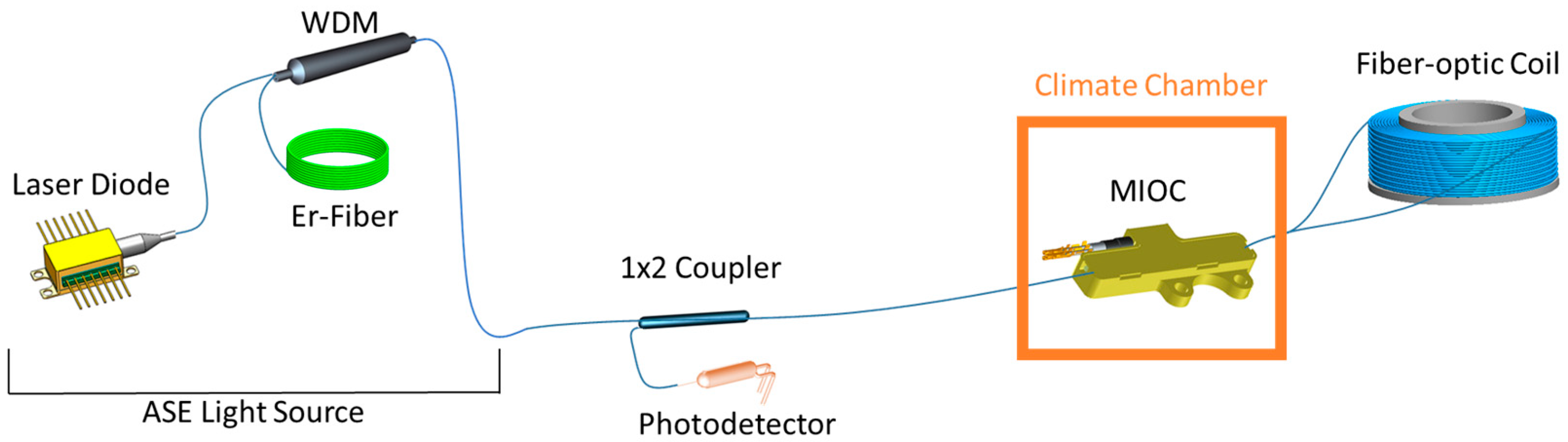
2.3. IFOG Bias Test Setup Configuration

The configuration of an IFOG primarily consists of the following essential components, namely a light source unit, directional couplers, a MIOC, and a fiber-optic coil. The impact of each component on the overall gyroscope performance is significant [56]. After the stand-alone characterization of each of the subunits is completed, optical connections are established step by step, performing power measurements at each stage. More information about the IFOG configuration, simulation, and development can be found in previous works [56,57,58,59,60].
The light source unit, in particular, is one of the critical components of IFOGs. Super luminescent diode (SLD) and erbium-based amplified spontaneous emission (ASE) light source configurations are commonly used to eliminate noise caused by Rayleigh backscattering and performance errors, due to the Kerr effect [6,61]. The ASE light source used in this study includes a pump laser, erbium-doped fiber, and a WDM (wavelength division multiplexer), generating an amplified spontaneous emission spectrum centered at 1550 nm [57]. A schematic representation of the IFOG bias test setup, including the ASE light source, is provided in Figure 5. The power consumption of the IFOG is 0.6 W for the laser diode and 0.5 W for the thermo-electric cooler (TEC). The fiber coil is another critical component influencing the measurement accuracy. Environmental factors can cause localized changes in the refractive index of the opposing light beams, a phenomenon known as the Shupe effect [62]. Consequently, polarization-maintaining (PM) fibers with symmetrical winding patterns (hexadecapole) are preferred [63]. The fiber coil used in the experiments was 1100 m long and the winding diameter was 85 mm. The dimensions of the navigation-grade IFOG were decided ultimately by the fiber coil size and were ø 100 mm × 25 mm.
The MIOC performs phase modulation, splits and combines light, while providing self-polarization, thus addressing issues related to unwanted noise and interference [27]. Bias drift is one of the most critical performance parameters in IFOG systems, especially in varying environmental conditions, such as temperature. Bias drift refers to unwanted deviations in the output signal of the gyroscope when there is no rotational movement, significantly affecting the accuracy of angular velocity measurements. In LiNbO3-based electro-optical modulators, DC drift is often linked to temperature fluctuations and instabilities in the applied DC voltage. This drift increases with temperature variations due to changes in the electro-optic coefficient and the refractive index of the modulator, leading to bias fluctuations between the counter-propagating light beams. A recent study shows that DC drift in LiNbO3-based electro-optical modulators fabricated using the APE method can be reduced with pre-annealing at 500 °C [36]. High-performance MIOCs play a crucial role in mitigating these temperature-induced phase shifts and maintaining accuracy in bias measurements.

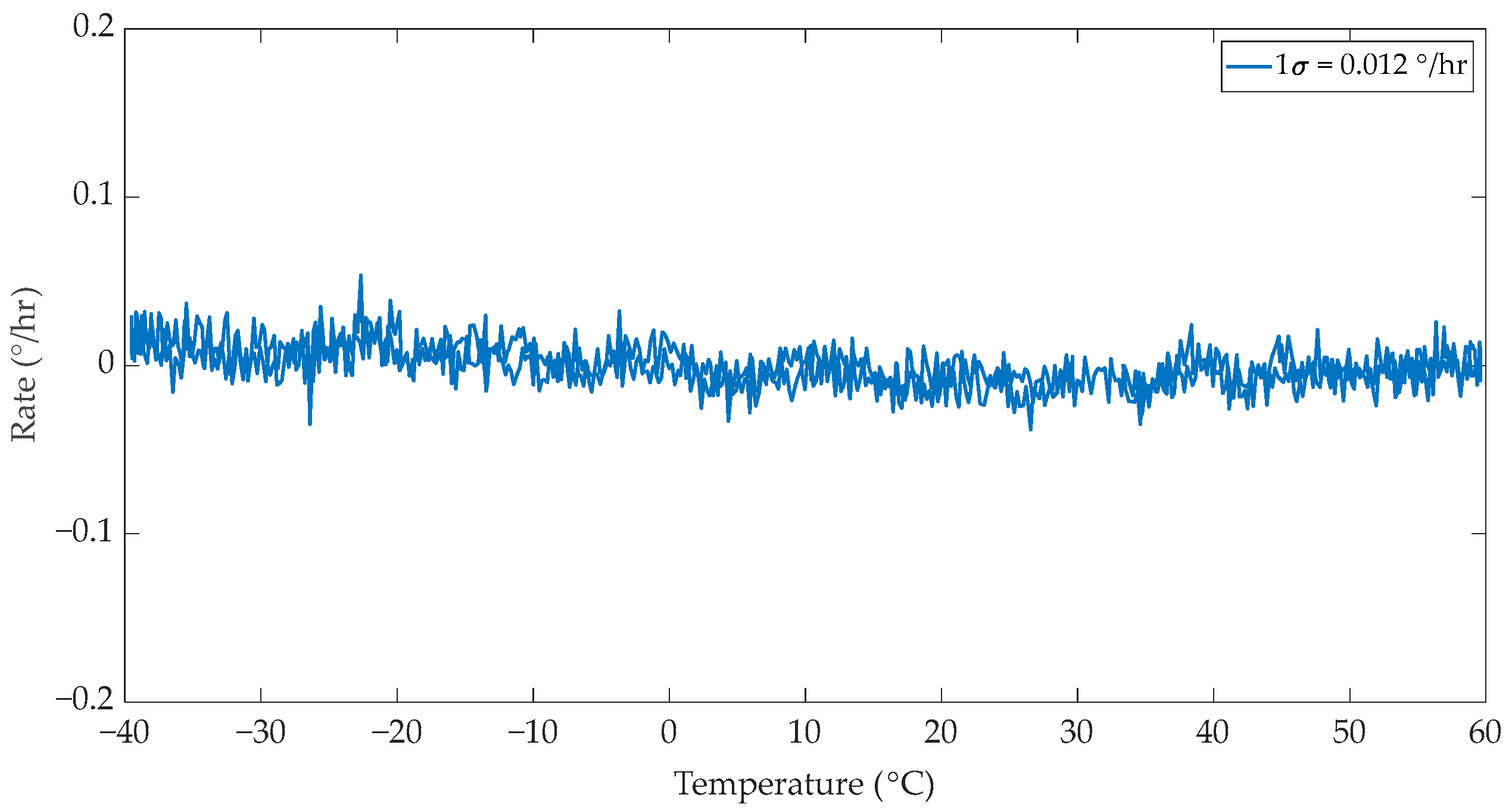
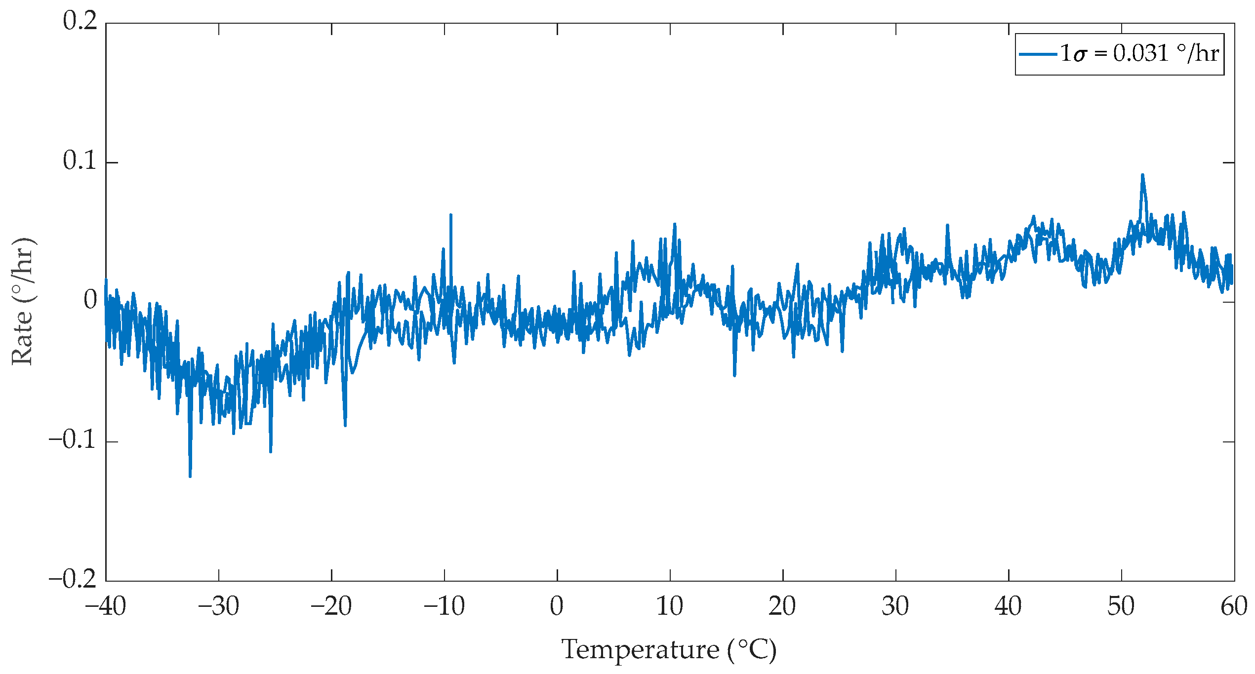
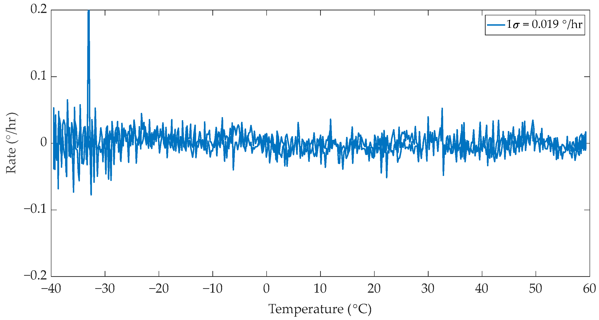
2.4. IFOG Bias Measurement Under Temperature Variations

Selected MIOCs have been tested to characterize their performance under changing temperature conditions. All measurements were conducted using a closed-loop fiber-optic gyroscope configuration, utilizing an identical light source, coupler, fiber coil, and detectors. During the tests, only the MIOC under test were placed inside the climate chamber, while all the other subsystems were maintained at room temperature. The tests were carried out with a temperature profile optimized in the range of −40 °C to +60 °C, focusing solely on the thermal behavior of the MIOCs when exposed to temperature changes. Prior to the thermal cycle tests, the ARW parameter of the constructed gyroscope was measured as 0.0056 deg/√h under non-changing environmental conditions, validating the navigation grade of the test setup.
Within the climate chamber, the environmental conditions were optimized to create a controlled atmosphere. During the measurement process, an environment was created to minimize vibrations and other external factors, ensuring the reliability of the obtained data. Subsequently, the temperature-dependent rate test was initiated and approximately 17 h of data were collected over the full temperature range, with a rate of 0.2 °C per minute.
For the IFOG bias tests, four MIOCs were randomly selected, two devices from the non-pre-annealed group and two devices from the pre-annealed group, as indicated by the throughput measurements in Table 1 of Section 2.2. These four MIOCs were optically connected using the same light source, fiber coil, and photodetectors, and integrated into the test setup.
The Earth’s rotation was measured as 9.6°/h in Ankara, Turkey, for all the tested IFOGs using these MIOCs and all the tests were calculated around zero rotation. The power and polarization measurements were conducted after each splice point in this configuration and no significant splice loss was observed.
In the first test, an IFOG configuration was established using a MIOC fabricated from the non-pre-annealed NPA-1 wafer, which is detailed in Table 1, and a temperature-dependent test was conducted. The IFOG bias test results are presented in Figure 6. It is observed that there is a bias drift and fluctuations at both negative and positive temperatures during the test. The 1σ value was obtained as 0.038°/h.
In the second test, a MIOC fabricated on the pre-annealed wafer PA-1 was used. The results of this test are presented in Figure 7. The MIOC fabricated on the pre-annealed PA-1 wafer exhibited very small bias drift and fluctuations compared to the previous test. The 1σ value is 0.012°/h, indicating that the bias performance of the MIOC produced from the pre-annealed wafer is better.
To further validate the test results, temperature-dependent IFOG bias tests were continued using a MIOC fabricated on the non-pre-annealed NPA-2 wafer. The test results are presented in Figure 8. Upon analyzing the test results, significant bias drift and fluctuations were observed. The 1σ value is obtained as 0.031°/h.
The fourth and final test was run using a MIOC fabricated on the pre-annealed PA-4 wafer. The test results are presented in Figure 9. It was observed that this MIOC exhibited a 1σ value of 0.019°/h, with small bias fluctuations. The bias drift was insignificant in this test. The peak in the bias value observed around −32 °C was caused by the environmental factors present during the testing process, such as vibrations affecting the measurement setup, which was placed outside the climate chamber.
Overall, the results show that IFOG bias drift and fluctuations were improved when MIOCs fabricated on pre-annealed wafers were used, as compared to when MIOCs fabricated on non-pre-annealed wafers were used. This low bias drift and improvement in the fluctuations in bias can be attributed to multiple factors, including better polarizing waveguides, higher effective throughput, and lower thermal and DC drift of the MIOC bias characteristics. The presence of bias drift and fluctuations in bias reduce the accuracy and reliability of rotation rate measurements and a low bias drift is crucial for ensuring the overall performance and precision of the system. Since MIOCs fabricated on pre-annealed wafers exhibit enhanced bias performance, these MIOCs are better suited for those applications requiring higher precision, stability, and reliability. This result reinforces the importance of wafer preparation methods in optimizing the operational characteristics of fiber-optic gyroscopes.

3. Discussion

The aim of this study was to investigate the performance of MIOCs fabricated on LiNbO3 wafers that are pre-annealed at 500 °C by comparing optical transmittance and system-level IFOG bias measurement results. It was observed that the pre-annealing process resulted in an improvement in the optical throughput of the MIOCs (from %34 to %51). In addition to the enhancement observed in the optical transmittance at room temperature, the temperature-dependent electro-optical stability of the MIOCs was improved as a result of the reduced defect layer thickness, following a reduction in both the amount of charge trap centers causing drift and the amount of thermal expansion-induced changes. This result is in agreement with the study in [36], where the pre-annealing process resulted in an improvement to the modulator DC drift characteristics.
The MIOCs were tested in an IFOG, with a measured ARW of 0.0056 deg/√h, in agreement with the target navigation-grade performance of the IFOG. System-level IFOG bias measurement tests in the temperature range from −40 °C to +60 °C were conducted, while only the MIOCs under test were placed in a climate chamber. The IFOG bias measurement results indicate that bias fluctuations under temperature variations significantly decrease with the use of MIOCs fabricated on pre-annealed wafers, compared to those fabricated on non-pre-annealed wafers. The temperature-dependent bias drift stability of the IFOG was improved from 0.031–0.038°/h for systems using non-pre-annealed MIOCs to 0.012–0.019°/h for identical systems where the only modification was the replacement of the non-pre-annealed MIOC with a MIOC fabricated on a pre-annealed wafer.
These results indicate that the bias drift performance of the MIOCs produced from pre-annealed wafers is significantly superior. This improvement can be attributed to the enhanced DC drift, polarization, and permeability characteristics achieved through the pre-annealing process, which effectively reduces the susceptibility to bias fluctuations. These findings underscore the importance of wafer preparation techniques in optimizing MIOC performance, making pre-annealed wafers the preferred choice for applications demanding high precision and stability.

Author Contributions

Conceptualization, fabrication and throughput measurements, F.Y.A., E.K. and M.G.; IFOG bias tests, E.E.A. and A.Y.; formal analysis and writing—review and editing, E.K., E.E.A., M.G., F.Y.A. and A.Y.; supervision, E.Ö. and Ş.Ö.; visualization, E.K. and A.Y.; writing—original draft, E.K. and E.E.A. All authors have read and agreed to the published version of the manuscript.

Funding

This research received no external funding.

Institutional Review Board Statement

Not applicable.

Informed Consent Statement

Not applicable.

Data Availability Statement

The original contributions presented in the study are included in the article material: further inquiries can be directed to the corresponding authors.

Conflicts of Interest

Author Şadan Özcan is employed by CW Enerji Müh. Tic. ve San. A.Ş. All authors declare that they have no conflicts of interest.

References

  1. Passaro, V.M.N.; Cuccovillo, A.; Vaiani, L.; De Carlo, M.; Campanella, C.E. Gyroscope Technology and Applications: A Review in the Industrial Perspective. Sensors 2017, 17, 2284. [Google Scholar] [CrossRef] [PubMed]
  2. Rozelle, D.M. The Hemispherical Resonator Gyro: From Wineglass to the Planets. In Proceedings of the 19th AAS/AIAA Space Flight Mechanics Meeting, Savannah, Georgia, 8–12 February 2009; Volume 134, pp. 1157–1178. [Google Scholar]
  3. Merlo, S.; Norgia, M.; Donati, S. Fiber Gyroscope Principles. In Handbook of Fibre Optic Sensing Technology; John Wiley & Sons, Ltd.: Hoboken, NJ, USA, 2000; pp. 1–23. [Google Scholar]
  4. Grattan, K.T.V.; Sun, T. Fiber Optic Sensor Technology: An Overview. Sens. Actuators A Phys. 2000, 82, 40–61. [Google Scholar] [CrossRef]
  5. Chow, W.W.; Gea-Banacloche, J.; Pedrotti, L.M.; Sanders, V.E.; Schleich, W.; Scully, M.O. The Ring Laser Gyro. Rev. Mod. Phys. 1985, 57, 61. [Google Scholar] [CrossRef]
  6. Lefevre, H.C. The Fiber-Optic Gyroscope; Artech House: Norwood, MA, USA, 2014; ISBN 1608076962. [Google Scholar]
  7. Sanders, G.A.; Szafraniec, B.; Liu, R.-Y.; Laskoskie, C.L.; Strandjord, L.K.; Weed, G. Fiber Optic Gyros for Space, Marine, and Aviation Applications. In Proceedings of the Fiber Optic Gyros: 20th Anniversary Conference, Denver, CO, USA, 4–9 August 1996; Volume 2837, pp. 61–71. [Google Scholar]
  8. Sanders, G.A.; Szafraniec, B.; Liu, R.-Y.; Bielas, M.S.; Strandjord, L.K. Fiber-Optic Gyro Development for a Broad Range of Applications. In Proceedings of the Fiber Optic and Laser Sensors XIII, Munich, Germany, 20–21 June 1995; Volume 2510, pp. 2–11. [Google Scholar] [CrossRef]
  9. Ma, K.; Song, N.; Jin, J.; He, J.; Zio, E. Configuration Optimization in Miniature Interferometric Fiber-Optic Gyroscopes for Space Application. IEEE Sens. J. 2020, 20, 7107–7117. [Google Scholar] [CrossRef]
  10. Wang, Y.-C.; Lu, S.-Y.; Yen, T.-H.; Wei, C.-C.; Chiu, Y.-J.; Liu, R.-Y.; Hung, Y.-J. Silicon Photonics Multi-Function Integrated Optical Circuit for Miniaturized Fiber Optic Gyroscope. J. Light. Technol. 2023, 41, 6324–6332. [Google Scholar] [CrossRef]
  11. Liu, K.; Zhang, W.; Chen, W.; Li, K.; Dai, F.; Cui, F.; Wu, X.; Ma, G.; Xiao, Q. The Development of Micro-Gyroscope Technology. J. Micromech. Microeng. 2009, 19, 113001. [Google Scholar] [CrossRef]
  12. Bogue, R. MEMS Sensors: Past, Present and Future. Sens. Rev. 2007, 27, 7–13. [Google Scholar] [CrossRef]
  13. Jin, L. Applications and Prospects of Mems Sensors in Automotive. Proc. J. Phys. Conf. Ser. 2021, 1884, 12010. [Google Scholar]
  14. Brown, A.K. Gps/Ins Uses Low-Cost Mems Imu. IEEE Aerosp. Electron. Syst. Mag. 2005, 20, 3–10. [Google Scholar] [CrossRef]
  15. Zhanshe, G.; Fucheng, C.; Boyu, L.; Le, C.; Chao, L.; Ke, S. Research Development of Silicon MEMS Gyroscopes: A Review. Microsyst. Technol. 2015, 21, 2053–2066. [Google Scholar] [CrossRef]
  16. Lai, Y.-H.; Suh, M.-G.; Lu, Y.-K.; Shen, B.; Yang, Q.-F.; Wang, H.; Li, J.; Lee, S.H.; Yang, K.Y.; Vahala, K. Earth Rotation Measured by a Chip-Scale Ring Laser Gyroscope. Nat. Photonics 2020, 14, 345–349. [Google Scholar] [CrossRef]
  17. Mahmoud, M.; Mahmoud, A.; Cai, L.; Khan, M.; Mukherjee, T.; Bain, J.; Piazza, G. Novel on Chip Rotation Detection Based on the Acousto-Optic Effect in Surface Acoustic Wave Gyroscopes. Opt. Express 2018, 26, 25060–25075. [Google Scholar] [CrossRef] [PubMed]
  18. Nayak, J. Fiber-Optic Gyroscopes: From Design to Production. Appl. Opt. 2011, 50, E152–E161. [Google Scholar] [CrossRef]
  19. Kajioka, H.; Kumagai, T.; Nakai, H.; Dohsho, T.; Soekawa, H.; Yuhara, T. Commercial Applications of Mass-Produced Fiber Optic Gyros. In Proceedings of the Fiber Optic Gyros: 20th Anniversary Conference, Denver, CO, USA, 4–9 August 1996; Volume 2837, pp. 18–32. [Google Scholar]
  20. Wang, Z.; Wang, G.; Kumar, S.; Marques, C.; Min, R.; Li, X. Recent Advancements in Resonant Fiber Optic Gyro—A Review. IEEE Sens. J. 2022, 22, 18240–18252. [Google Scholar] [CrossRef]
  21. Hotate, K. Future Evolution of Fiber Optic Gyros. Opt. Rev. 1997, 4, 28–34. [Google Scholar] [CrossRef]
  22. Ma, H.; Chang, X.; Mao, H.; Jin, Z. Laser Frequency Noise Limited Sensitivity in a Resonator Optic Gyroscope. In Proceedings of the OECC 2010 Technical Digest, Sapporo, Japan, 5–9 July 2010; pp. 706–707. [Google Scholar]
  23. Sanders, G.A. Critical Review of Resonator Fiber Optic Gyroscope Technology. In Proceedings of the Society of Photo-Optical Instrumentation Engineers (SPIE) Conference Series, Boston, MA, USA, 8-11 September 19921993; Volume 10266, p. 102660A. [Google Scholar] [CrossRef]
  24. Song, N.; Xu, X.; Zhang, Z.; Gao, F.; Wang, X. Advanced Interferometric Fiber Optic Gyroscope for Inertial Sensing: A Review. J. Light. Technol. 2023, 41, 4023–4034. [Google Scholar] [CrossRef]
  25. Rajulapati, R.M.; Nayak, J.; Naseema, S. Modeling and Simulation of Signal Processing for a Closed Loop Fiber Optic Gyro’s Using FPGA. Int. J. Eng. Sci. Techn. 2012, 4, 947–959. [Google Scholar]
  26. Lefevre, H.C.; Bettini, J.P.; Vatoux, S.; Papuchon, M. Progress in Optical Fiber Gyroscopes Using Integrated Optics. In AGARD Guided Optical Structures in the Military Environment; National Aerospace Library: Farnborough, UK, 1986. [Google Scholar]
  27. Korkishko, Y.N.; Fedorov, V.A.; Kostritskii, S.M.; Alkaev, A.N.; Paderin, E.M.; Maslennikov, E.I.; Apraksin, D.V. Multifunctional Integrated Optical Chip for Fiber Optical Gyroscope Fabricated by High-Temperature Proton Exchange. In Integrated Optical Devices: Fabrication and Testing; International Society for Optics and Photonics: Bruges, Belgium 2002, 2003; Volume 4944, pp. 262–267. [Google Scholar] [CrossRef]
  28. Wooten, E.L.; Kissa, K.M.; Yi-Yan, A.; Murphy, E.J.; Lafaw, D.A.; Hallemeier, P.F.; Maack, D.; Attanasio, D.V.; Fritz, D.J.; McBrien, G.J.; et al. Review of Lithium Niobate Modulators for Fiber-Optic Communications Systems. IEEE J. Sel. Top. Quantum Electron. 2000, 6, 69–82. [Google Scholar] [CrossRef]
  29. Korkishko, Y.N.; Fedorov, V.A.; Feoktistova, O.Y. LiNbO3 Optical Waveguide Fabrication by High-Temperature Proton Exchange. J. Light. Technol. 2000, 18, 562. [Google Scholar] [CrossRef]
  30. Schmidt, R.V.; Kaminow, I.P. Metal-diffused Optical Waveguides in LiNbO3. Appl. Phys. Lett. 1974, 25, 458–460. [Google Scholar] [CrossRef]
  31. Suchoski, P.G.; Findakly, T.K.; Leonberger, F.J. LiNbO3 Integrated Optical Components for Fiber Optic Gyroscopes. In Proceedings of the Integrated Optical Circuit Engineering VI, Boston, MA, USA, 7–9 September 1988; Volume 993, pp. 240–245. [Google Scholar] [CrossRef]
  32. Il’ichev, I.V.; Kozlov, A.S.; Gaenko, P.V.; Shamray, A.V. Optimisation of the Proton-Exchange Technology for Fabricating Channel Waveguides in Lithium Niobate Crystals. Quantum Electron. 2009, 39, 98. [Google Scholar] [CrossRef]
  33. Sosunov, A.V.; Petukhov, I.V.; Zhuravlev, A.A.; Ponomarev, R.S.; Mololkin, A.A.; Kuneva, M. Influence of Thermal Pretreatment of Lithium Niobate Plates on the Characteristics of Proton-Exchange Waveguides. Crystallogr. Rep. 2022, 67, 980–986. [Google Scholar] [CrossRef]
  34. Sosunov, A.V.; Ponomarev, R.S.; Mushinsky, S.S.; Volyntsev, A.B.; Mololkin, A.A.; Maléjacq, V. Effect of the Structure of the Lithium Niobate Surface Layer on the Characteristics of Optical Waveguides. Crystallogr. Rep. 2020, 65, 786–791. [Google Scholar] [CrossRef]
  35. Sosunov, A.; Ponomarev, R.; Semenova, O.; Petukhov, I.; Volyntsev, A. Effect of Pre-Annealing of Lithium Niobate on the Structure and Optical Characteristics of Proton-Exchanged Waveguides. Opt. Mater. 2019, 88, 176–180. [Google Scholar] [CrossRef]
  36. Sosunov, A.; Ponomarev, R.; Zhuravlev, A.; Mushinsky, S.; Kuneva, M. Reduction in Dc-Drift in LiNbO3-Based Electro-Optical Modulator. Photonics 2021, 8, 571. [Google Scholar] [CrossRef]
  37. Adams, G.; Barnett, N.; Insley, L.; Vajda, S. Evolution of Precision IFOG. In Proceedings of the 57th Annual Meeting of The Institute of Navigation, Albuquerque, NM, USA, 11–13 June 2001; pp. 200–204. [Google Scholar]
  38. Celikel, O.; San, S.E. Establishment of All Digital Closed-Loop Interferometric Fiber-Optic Gyroscope and Scale Factor Comparison for Open-Loop and All Digital Closed-Loop Configurations. IEEE Sens. J. 2009, 9, 176–186. [Google Scholar] [CrossRef]
  39. Papuchon, M.; Puech, C. Integrated Optics-A Possible Solution for the Fiber Gyroscope. In Proceedings of the Laser Inertial Rotation Sensors, SPIE, San Diego, CA, USA, 30–31 August 1978; Volume 157, pp. 218–223. [Google Scholar] [CrossRef]
  40. Korkishko, Y.N.; Fedorov, V.A.; Prilutskii, V.E.; Ponomarev, V.G.; Morev, I.V.; Skripnikov, S.F.; Khmelevskaya, M.I.; Buravlev, A.S.; Kostritskii, S.M.; Fedorov, I. V Strapdown Inertial Navigation Systems Based on Fiber-Optic Gyroscopes. Gyroscopy Navig. 2014, 5, 195–204. [Google Scholar] [CrossRef]
  41. Bi, R.; She, X.; Huang, T.; Shu, X. Temperature Modeling of Modulation Phase Error in the Integrated Optical Chip for Closed-Loop Interferometric Fiber Optic Gyroscope. Opt. Eng. 2019, 58, 67104. [Google Scholar] [CrossRef]
  42. Lefèvre, H.C. The Fiber-Optic Gyroscope: Challenges to Become the Ultimate Rotation-Sensing Technology. Opt. Fiber Technol. 2013, 19, 828–832. [Google Scholar]
  43. Guattari, F.; Moluçon, C.; Bigueur, A.; Ducloux, E.; De Toldi, E.; Honthaas, J.; Lefèvre, H. Touching the Limit of FOG Angular Random Walk: Challenges and Applications. In Proceedings of the 2016 DGON Intertial Sensors and Systems (ISS), Karlsruhe, Germany, 20–21 September 2016; pp. 1–13. [Google Scholar] [CrossRef]
  44. Shen, C.; Chen, X. Analysis and Modeling for Fiber-Optic Gyroscope Scale Factor Based on Environment Temperature. Appl. Opt. 2012, 51, 2541–2547. [Google Scholar] [CrossRef]
  45. Kurbatov, A.M.; Kurbatov, R.A.; Goryachkin, A.M. Fiber-Optic Gyroscope Accuracy Improvement by Suppressing the Parasitic Effects in Integrated Optic Phase Modulators. Gyroscopy Navig. 2019, 10, 256–267. [Google Scholar] [CrossRef]
  46. Miranda, M.; Takei, N.; Miyazawa, Y.; Kozuma, M. Multi-Harmonic Modulation in a Fiber-Optic Gyroscope. Sensors 2023, 23, 4442. [Google Scholar] [CrossRef] [PubMed]
  47. Salvestrini, J.P.; Guilbert, L.; Fontana, M.; Abarkan, M.; Gille, S. Analysis and Control of the Dc Drift in LiNbO3-Based Mach-Zehnder Modulators. J. Light. Technol. 2011, 29, 1522–1534. [Google Scholar] [CrossRef]
  48. Weis, R.S.; Gaylord, T.K. Lithium Niobate: Summary of Physical Properties and Crystal Structure. Appl. Phys. A 1985, 37, 191–203. [Google Scholar] [CrossRef]
  49. Lu, P.; Wang, Z.; Luo, R.; Zhao, D.; Peng, C.; Li, Z. Polarization Nonreciprocity Suppression of Dual-Polarization Fiber-Optic Gyroscope under Temperature Variation. Opt. Lett. 2015, 40, 1826–1829. [Google Scholar] [CrossRef]
  50. Jackel, J.L.; Rice, C.E.; Veselka, J.J. Proton Exchange for High-index Waveguides in LiNbO3. Appl. Phys. Lett. 1982, 41, 607–608. [Google Scholar] [CrossRef]
  51. Suchoski, P.; Findakly, T.K.; Leonberger, F.J. Stable Low-Loss Proton-Exchanged LiNbO3 Waveguide Devices with No Electro-Optic Degradation. Opt. Lett. 1988, 13, 1050–1052. [Google Scholar] [CrossRef]
  52. Yasemin Aşık, F.; Gökkavas, M.; Öztekin, E.; Karagöz, E.; Ceylan, A.; Özbay, E. Optimization of the Annealed Proton Exchange Method with Controlled Annealing for Multifunctional Integrated Optical Chip Production. Appl. Opt. 2022, 61, 8898–8903. [Google Scholar] [CrossRef]
  53. Dönertaş, S.; Gökkavas, M.; Özbay, E.; Orhan, E.Ö. Determining Thermo-Mechanical Stress Sources of an Integrated Optical Device. Optik 2021, 242, 167281. [Google Scholar] [CrossRef]
  54. Dönertaş, S.; Gökkavas, M.; Özbay, E.; Orhan, E. Case Study for Thermo Mechanical Performance of an Integrated Optic Device via Equation-Based Modelling. Gazi Univ. J. Sci. Part A Eng. Innov. 2021, 8, 135–145. [Google Scholar]
  55. Kanlı, Y.; Öztekin, E.; Dönertaş, S.; Gökkavas, M.; Ozbay, E. Ti-Indiffused Waveguide Polarizers on Lithium Niobate for Fiber Optic Gyroscope. In Proceedings of the Optical Fiber Sensors, Lausanne, Switzerland, 24–28 September 2018; p. WF51. [Google Scholar]
  56. Yertutanol, A.; Akçaalan, Ö.; Öğüt, S.; Özbay, E.; Ceylan, A. Fiber-Optic Gyroscope for the Suppression of a Faraday-Effect-Induced Bias Error. Opt. Lett. 2021, 46, 4328–4331. [Google Scholar] [CrossRef]
  57. Akbaş, E.E.; Yertutanol, A.; Andaç, T.; Özbay, E.; Azizian-Kalandaragh, Y. Optimization of ASE Light Source Design for Enhancement of Wavelength Stability. In Proceedings of the 2023 IEEE SENSORS, Vienna, Austria, 29 October–1 November 2023; pp. 1–4. [Google Scholar]
  58. Andac Senol, T.; Akcaalan, O.; Yertutanol, A.; Ozbay, E. A Novel Method to Eliminate the Symmetry Dependence of Fiber Coils for Shupe Mitigation. Sci. Rep. 2024, 14, 9076. [Google Scholar] [CrossRef] [PubMed]
  59. Osunluk, B.; Ogut, S.; Ozbay, E. Thermally Induced Bias Error Due to Strain Inhomogeneity through the Fiber Optic Gyroscope Coil. Appl. Opt. 2020, 59, 10416–10421. [Google Scholar] [CrossRef] [PubMed]
  60. Ogut, S.; Osunluk, B.; Ozbay, E. Modeling of Thermal Sensitivity of a Fiber Optic Gyroscope Coil with Practical Quadrupole Winding. In Proceedings of the Fiber Optic Sensors and Applications XIV, Anaheim, CA, USA, 11–12 April 2017; Volume 10208, pp. 32–37. [Google Scholar] [CrossRef]
  61. Hsiao, C.W.; Fang, Y.-H.; Chen, Y.-J.; Weng, Z.-Y.; Chu, J.-Y.; Chen, R.-Y.; Dong, C.-H.; Lin, W.; Chiu, Y.-J. Fabrication of Superluminescent Diode (SLD) for Gyro Light Source with Broadband, High Power, and Large Polarization-Extinction Ratio Performance. In Proceedings of the 2020 Opto-Electronics and Communications Conference (OECC), IEEE, Taipei, Taiwan, 4–8 October 2020; pp. 1–3. [Google Scholar] [CrossRef]
  62. Shupe, D.M. Thermally Induced Nonreciprocity in the Fiber-Optic Interferometer. Appl. Opt. 1980, 19, 654–655. [Google Scholar] [CrossRef] [PubMed]
  63. Hong, W.; Hu, X.; Zang, Z.; Zhang, P.; Lou, S.; Huang, B.; Li, Y.; Zhang, M. Accurate Measurement and Enhancement of Fiber Coil Symmetry. Appl. Opt. 2023, 62, E109–E118. [Google Scholar] [CrossRef]
Figure 1. A fiber coil rotating with a clockwise angular velocity: (a) the different optical paths of the clockwise (CW) and counterclockwise (CCW) optical beams, (b) the same difference Δl between the optical paths of the clockwise and counterclockwise beams due to rotation, along with the stationary optical path.
Photonics 11 01057 g001
Figure 2. Schematic representation of the MIOC. The MIOC is a device that polarizes the light coupled into it via a fiber, splits the light into two arms with the help of a Y splitter, and modulates the phase of the light in these two arms.
Photonics 11 01057 g002
Figure 3. MIOC fabrication steps: (a) AZ2070 spin coating, (b) photoresist patterned using waveguide mask, (c) Ti coating, (d) lift-off process, (e) proton exchange process, (f) Ti etch and annealing, (g) AZ2070 spin coating, (h) photoresist patterned using electrode mask, (i) Ti–Au coating, and (j) lift-off process.
Photonics 11 01057 g003
Figure 4. Scatter plot comparison of total throughput measurements for MIOCs fabricated on non-pre-annealed and pre-annealed wafers.
Photonics 11 01057 g004
Figure 5. IFOG test setup used in the bias measurements.
Photonics 11 01057 g005
Figure 6. Temperature-dependent IFOG bias measurement with a MIOC fabricated on the non-pre-annealed NPA-1 wafer.
Photonics 11 01057 g006
Figure 7. Temperature-dependent IFOG bias measurement with a MIOC fabricated on the pre-annealed PA-1 wafer.
Photonics 11 01057 g007
Figure 8. Temperature-dependent IFOG bias measurement with a MIOC fabricated on the non-pre-annealed NPA-2 wafer.
Photonics 11 01057 g008
Figure 9. Temperature-dependent IFOG bias measurement with a MIOC fabricated on the pre-annealed PA-4 wafer.
Photonics 11 01057 g009
Table 1. Total throughput measurements of 32 MIOCs fabricated on 4 non-pre-annealed and 4 pre-annealed wafers.
Non-Pre-Annealed (NPA) WafersPre-Annealed (PA) Wafers
Wafer NameNPA-1NPA-2NPA-3NPA-4PA-1PA-2PA-3PA-4
Total throughput MIOC #1 (%) 29.1033.7037.8035.6052.5048.1049.4051.20
Total throughput MIOC #2 (%)30.0036.3031.4035.8051.9046.1049.6052.10
Total throughput MIOC #3 (%)36.3032.6035.2037.1053.9044.0052.1053.60
Total throughput MIOC #4 (%)32.4029.3032.8037.0054.3047.9051.7054.20
Mean (per wafer) (%)31.9532.9834.3036.3853.1546.5350.7052.78
Standard deviation (per wafer)3.222.902.810.781.141.911.401.37
Mean (%)33.9050.79
Standard deviation2.893.02
Disclaimer/Publisher’s Note: The statements, opinions and data contained in all publications are solely those of the individual author(s) and contributor(s) and not of MDPI and/or the editor(s). MDPI and/or the editor(s) disclaim responsibility for any injury to people or property resulting from any ideas, methods, instructions or products referred to in the content.

