1. Introduction
The laser time transfer technology offers the highest precision for synchronizing clocks between remote platforms, finding applications in precision navigation and timing [
1], geodetic clock-based measurements [
2,
3], coherent radar arrays [
4], and long baseline interferometry for gravitational wave detection [
5]. Current laser time transfer methods include single-photon detector-based time transfer, which measures the flight time of picosecond laser pulses [
6]; two-way time transfer using frequency combs [
7]; and time transfer with quantum-correlated photon pairs [
8]. Single-photon detection allows a measurement using two-way links, where one end only has a passive optical retroreflector, eliminating the need for laser and beam tracking, making it widely used in satellite–ground time transfer [
9,
10,
11]. However, this method is constrained by the time jitter of the single-photon detector, with precision at the picosecond level [
10,
11]. Frequency comb-based time transfer is currently the most precise reported method. Research groups have demonstrated two-way frequency comb time transfer experiments over distances of 113 km and 300 km in free space, achieving sub-femtosecond precision [
12,
13]. These results indicate the feasibility of using low-power frequency combs with a 10 cm aperture for time transfer between geosynchronous orbit satellites and the ground.
In recent years, the rapid development of near-Earth orbit satellite networks such as Starlink has highlighted the importance of high-precision clock synchronization for these small satellites supporting a higher precision navigation than GPS and Beidou. However, this technology still faces significant challenges, including a weight limit of less than ~1 kg, an operating range of at least 5000 km, a clock synchronization accuracy better than 20 ps, and dealing with maximum relative moving speeds of the satellites exceeding 10 km/s. The current frequency combs scenario is not suitable for clock synchronization between small satellites due to several reasons: (1) the fast relative motion speed between satellites introduces a severe Doppler effect that cannot be overcome by the frequency combs scenario [
14]; (2) the frequency combs time transfer system struggles to meet lightweight requirements; (3) the high cost of the frequency combs time transfer system makes it difficult to satisfy the needs of low-cost applications.
In this paper, we examine the effect of relative motion on laser time transfer and introduce a lightweight laser time transfer scenario tailored for small satellite applications. The clock offset measurement performance and the necessary satellite flight speed parameters are evaluated through numerical simulations. The results indicate that the clock offset measurement precision can exceed 3 ps within a distance range of 2000 km to 5000 km, provided the speed accuracy is ±0.06 m/s.
2. Theory
Two-way laser ranging and clock synchronization technology enable distance and clock offset measurements between two distant platforms by asynchronously transmitting laser pulses to each other, measuring the emission and arrival times of these pulses. Unlike the traditional two-way links, the signal loss in a two-way optical link can be reduced from being proportional to
to
, where R denotes the distance between two terminals. As illustrated in
Figure 1, platform A records the laser pulse emission time
using its local clock A, as well as the arrival time
of the pulse from platform B; similarly, platform B measures
and
based on its local clock B. Subsequently, both platforms exchange their measurement data and calculate the distance and clock offset using these four recorded times.
Assuming that the clock A is the main reference clock, the clock offset between clock B and clock A is
. To align
and
with the reference of clock A, it can be as follows:
and
. For two stationary platforms, the distance measured in both directions should be equal, meaning
. Here,
and
, where c represents the speed of light. From these equations, we can derive formulas for calculating the clock offset and distance as follows:
The single-pulse measurement precisions of clock offset and distance, as described in Equations (3) and (4), are derived using the standard deviation, based on Equations (1) and (2), given that the simulations and measurements in this study are independent.
However, Equations (1) and (2) do not account for the impact of relative motion between the platforms. For high-speed moving platforms like satellites, it is crucial to consider the effects of relative motion. It is assumed that the displacement during the measurement time is significantly smaller than the platform spacing, and both platforms move at constant speeds, denoted as vector quantities
and
, respectively. In the general case, the velocities of the satellites should be treated as vectors, and the relative velocity should be calculated using vector addition to account for arbitrary motion directions. In the specific case where the motion of both platforms is aligned along the laser flight direction, the relative velocities of platform A and platform B can be represented by their projections along this direction, denoted as
and
. When the moving direction of the platform is the same as the laser flight direction emitted from the opposite platform,
(
) is taken as positive, and vice versa is taken as negative. In this case, the relative velocity between the platforms can be simplified to
. When the light pulse is emitted from platform A, the flight time of the light pulse reaching platform B is independent of the motion of platform A. Due to the satellite’s high velocity of up to 10 km/s, relativistic effects must be taken into account. Assuming the current distance is
according to the relativistic theory for time comparisons in the vicinity of the Earth (GCRS) [
15], the flight distance of the laser pulses from platform A to platform B is as follows:
The variable
represents the acceleration of satellite B, while
denotes the geocentric gravitational constant.
and
correspond to the magnitudes of the position vectors of platforms A and B at the time of signal emission, respectively. The second and third terms in the equation represent different orders of the Sagnac term [
16]. The Sagnac term of order
can reach up to 200 nanoseconds for low Earth orbit satellites (LEOs) and 133 ns for GPS. The Sagnac term of order
is a few picoseconds (up to 10 ps for geostationary satellites). The fourth term in the equation, the logarithmic term, accounts for the Shapiro time delay. For low Earth orbit satellites (LEOs) and ground stations, the Shapiro time delay is a few picoseconds, while for GPS or geostationary satellites, it is a few tens of picoseconds. In this study, both the simulations and experiments were conducted with a single detection duration of no more than 50 ms. Within this brief period, the change in the satellite’s velocity is negligible, allowing the motion to be approximated as uniform. Consequently, the effect of acceleration
can be disregarded. Moreover, when compared to the Sagnac term, the contribution of the Shapiro time delay is insignificant and can also be ignored. Therefore, Equation (
6) is derived, focusing primarily on the Sagnac term and detailing the Sagnac terms from order
up to
.
Compared to stationary platforms, an additional motion correction term is introduced here. Let
, then Equation (
6) simplifies to
In two-way ranging, there is a random delay
between the laser pulses coming from different platforms. At time
, the distance between the platforms is
, where
. The flight distance of the light pulse emitted at time
from platform B to platform A is as follows:
Here,
. According to Equations (7) and (8), the clock offset is obtained as
Compared to stationary platforms, relative motion velocity is an essential parameter for measuring clock bias. The reference [
17] provides a clock offset measurement between the satellite and the ground, considering only the relative motion velocity between the platforms.This is because with the ground as the reference frame, the ground station is stationary, and the relative motion velocity between the two platforms is the contribution of satellite motion to the relative motion velocity. For two platforms that are both in motion, high-precision measurement of clock errors requires not only the relative motion velocity
between the two platforms, but also the contribution of each platform to the relative motion velocity
and
.
3. Method and Simulation
Two-way laser ranging and clock synchronization hold great potential for small satellite applications. In this paper, we propose a scenario for two-way single-photon laser time transfer and evaluate its performance through numerical simulation. The devices and their specifications are listed in
Table 1, with technical parameters that current equipment can achieve [
18,
19,
20,
21,
22]. This setup uses an Nd:YAG microchip laser at 532 nm, characterized by high repetition rate and low energy, paired with a single-pixel silicon single-photon avalanche photodiode (SPAD). Assuming satellite separations of 2000–5000 km, a laser beam divergence angle of 1.5 mrad, a receiving aperture of 20 mm, and an overall optical system transmittance of 0.6, the average number of received photons per pulse is approximately 1.4 to 0.2. The clocks on both platforms are typically high-precision rubidium atomic clocks, known for their excellent time stability, with a deviation of less than 1 ps per day and jitter under 1 ps [
23].
As shown in
Table 1, the SPAD’s time jitter (
ps), along with other key jitter sources—such as the laser pulse width (
), time synchronization jitter (
), and event timer jitter (
)—are all factored into the simulation. These jitter components collectively impact the measurement precision, as detailed in Equations (10)–(13). The measurement precision of
,
,
,
are
For the stationary platforms, according to Equations (3), (10)–(13), the single-pulse measurement precision of the clock offset can be calculated as 124 ps. In this scenario, high repetition rate laser pulses are employed to accumulate a large number of signal photons in a brief interval, subsequently acquiring multiple datasets. By determining the centroid of these datasets, the uncertainty in the clock offset,
, can be significantly reduced [
24,
25,
26].
The flight speeds of near-Earth satellites exceed 7 km/s, and the distance between satellites can exceed 2000 km, making relative motion a significant factor in clock offset measurements. Such challenging operational conditions are almost impossible to replicate in ground-based experiments. Therefore, we assess and analyze the performance of clock offset measurements through numerical simulations. For simplicity, it is assumed that two near-Earth satellites are moving at constant speeds around an idealized circular orbit. Their respective flight speeds are and , with an initial clock offset is , and an initial separation distance at time . With these parameters, the spatial coordinates of the satellites at any given time can be calculated, which in turn allows for the computation of satellite separation.
Then we simulate the process of laser pulse emission, transmission, and detection, and assign values to the four measurement times. Starting from
, the time series of
is
where
i is a non-zero integer, and
T is the laser pulse period.
denotes the moment of laser emission from platform A according to clock A, without any detection error.
represents the delay between the pulse emission of the passive Q-switched laser and its electric trigger pulse, modeled in the formula as Rand
, which is uniformly distributed, typically within 100 ns.
represents the measurement error in the laser pulse synchronization signal, modeled in the formula as Rand
, which is Gaussian-distributed and typically within
(FWHM).
When the laser pulse reaches satellite B, the time series of the arrival time
measured by the SPAD is
where Rand
is a Gaussian distributed measurement error of photon pulses within
(FWHM).
Similarly, the time series of
and
are
A complete set of measurements includes four times:
,
,
,
, where
and
(similarly
and
) need to originate from the same laser pulse. Since
and
are detected by the SPAD, instances occur where they may not be detected. Therefore, the two closest sets of
and
measurement values are selected to calculate the clock offset using Equation (
9).
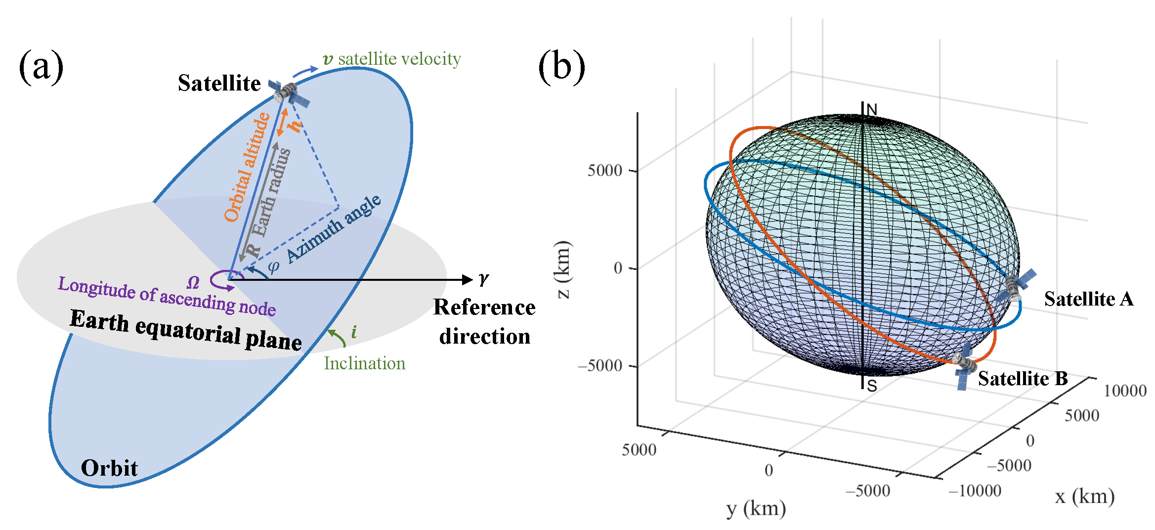
A satellite orbit model is constructed, as depicted in
Figure 2a, with the Earth’s equatorial plane serving as the reference plane and a specified reference direction. The orbit of the satellite is uniquely defined by three parameters: the inclination
i, the right ascension of the ascending node
, and the orbital altitude
h. The precise position of the satellite is then determined by the azimuth angle
. By incorporating the satellite velocity
v, the model allows for the simulation of the satellite’s real-time coordinates during its motion.To analyze parameters such as inter-satellite distance and relative velocity, the satellites’ coordinates are transformed into a Cartesian coordinate system, as shown in
Figure 2b, enabling accurate calculation of these dynamics. Achieving laser transmission between satellites in practical experiments presents several technical challenges. The high relative velocity between satellites in orbit complicates precise beam alignment and transmission, which may result in signal loss. Additionally, errors in orbit prediction can affect the transmission path, further complicating alignment. Therefore, stable laser transmission requires high-precision beam alignment and satellite tracking systems to counteract the adverse effects of high relative velocities and orbital variations.
Firstly, we numerical simulate
, assuming the satellite velocity error is zero. Assuming an initial distance of 2000 km between two satellites, and a relative velocity of 1.9 km/s. As shown in
Figure 3a, the
improves as the number of detected photons increases. When more than 500 photons are detected,
approaches 5 ps (FWHM). For a laser with a 500 kHz repetition rate, it requires only a brief measurement time of 1 ms, given a signal photon pulses detection rate of 10%. This is highly advantageous for the satellite to rapidly complete clock offset measurements with multiple satellites in a short period. In the following simulation analysis, the selected operation conditions are as follows: the detection probability of the photon pulses is 10%, the repetition rate is 500 kHz, the measurement time is 50 ms, and the satellite spacing is 5000 km.
Due to the significant impact of satellite flight on
, it is imperative to carefully consider satellite velocity.
Figure 3b shows how
varies with different levels of velocity accuracy for
and
. The influence of velocity accuracy on
is greater than that of the laser time transfer system itself. To achieve a
of less than 20 ps, the velocity accuracy of both satellites must be maintained within ±0.3 m/s.
In order to calculate the relative velocity based on the measurement times, we select two sets of
and
(
and
). Assuming they are
,
,
,
,
,
,
,
, where
i,
k,
j,
l are the non-zero integers. Assuming that the satellites spacing is much longer than the displacement during the measurement time. According to Equation (
7), the distance difference between satellites of different pulse periods can be calculated, which corresponds to the relative displacement of the satellites during this period:
Similarly, it can be concluded that
In the general case, the vector addition of
and
must be used to determine the relative velocity
accurately. However, when both platforms are aligned along the laser direction, the simplified scalar addition approach can be applied. Equations (18) and (19) are solved as follows:
The relative velocity
in this specific case can be calculated according to Equation (
26). As shown in
Figure 4a, the calculation accuracy of
is closely related to the measurement time. The accuracy of
is better than
m/s when the measurement time is 50 ms.
The longer the measurement time, the higher the accuracy of relative velocity measurement. However, the precise measurement of
and
requires accurate determination of the tiny differences between
and
, as well as accounting for measurement errors in photon detection, which can lead to significant measurement errors.
Figure 4b shows the difference between the measurement clock offset caused by the velocity error of
(
) and the real value while
. There is a linear relationship between them. The difference is less than 20 ps when the velocity error is less than 0.35 m/s, which is close to the results in
Figure 3b. This indicates that with or without the constraint of
, high-accuracy clock offset measurement cannot be achieved without accurate
(
).
As a result, an alternative method for velocity measurement is necessary to obtain accurate flight velocities for at least one of the satellites. Assuming that some satellites in network are equipped with Doppler radars, by measuring the relative velocity obliquely downward towards the ground, the satellite’s flight velocity along the orbit can be calculated with a measurement accuracy better than 0.01 m/s [
27,
28,
29,
30]. With the assistance of the Doppler radar, the measurement accuracy of
and
reaches ±0.06 m/s when the measurement time is 50 ms.
4. Results
We numerically simulate the
under various relative velocities and inter-satellite distances, based on a velocity accuracy of ± 0.06 m/s. As demonstrated in
Figure 5, with a repetition rate of 500 kHz and a measurement time of 50 ms,
is better than 3 ps (FWHM). As the distance increases,
slightly increases, primarily due to a reduction in the total number of detected signal photons. On the other hand,
does not significantly change with variations in relative velocity. Moreover, the difference between the measured clock offset and the true value changes by approximately ±3.3 ps, when the variation range of the speed error is ±0.06 m/s. Under this condition, not only can high precision be achieved, but also high accuracy clock offset measurement can be obtained.
During a time period much longer than the measurement time, it can be assumed that the change in clock offset between satellites is much less than the measurement accuracy. Based on this assumption, by calculating the centroid of multiple sets of clock offset measurements over a short period of time, the precision of the clock offset measurement can be substantially improved. The laser time transfer technology, which utilized high repetition rate laser pulses, is particularly suitable for acquiring a large volume of effective measurement data in a brief interval, thereby facilitating clock offset measurements with multiple satellites in a short span.
In conclusion, we propose a laser time transfer scenario that employs a high repetition rate microchip laser and a single-pixel SPAD to achieve high-speed inter-satellite clock offset measurements. The laser’s weight is under 400 g, and the receiving aperture is 20 mm, meeting the lightweight requirements of small satellites. We have not only determined the relative velocity between satellites, but also that the contribution of each satellite to the relative velocity must be accurately measured to correctly compensate for motion-induced measurement errors. The simulation results indicate that the clock offset measurement precision and accuracy could be better than 3 ps, with a velocity accuracy of ±0.06 m/s. For clock synchronization among near-Earth satellites, this scenario is the lightest and most accurate one known to us.


