Article

Design of a Spaceborne, Compact, Off-Axis, Multi-Mirror Optical System Based on Freeform Surfaces

1
School of Optoelectronic Engineering, Changchun University of Science and Technology, Changchun 130022, China
2
Beijing Institute of Space Mechanics and Electricity, Beijing 100094, China
*
Author to whom correspondence should be addressed.
Photonics 2024, 11(1), 51; https://doi.org/10.3390/photonics11010051
Submission received: 4 December 2023 / Revised: 23 December 2023 / Accepted: 28 December 2023 / Published: 3 January 2024
(This article belongs to the Special Issue New Advances in Freeform Optics Design)

Abstract

:
Based on the application requirements of high spectral resolutions, high spatial resolutions and wide swatches, a new-generation, high-performance, spaceborne, hyperspectral imaging spectrometer (NGHSI) with a spatial resolution of 15 m and a swatch of 90 km is proposed. The optical system of the NGHSI has a focal length of 1128 mm, an F-number of three, a field of view (FOV) of 7.32° and a slit length of 144 mm. A new off-axis, multi-mirror telescope structure with intermediate images is put forward, which solves the design problem that realizes secondary imaging and good telecentricity at the same time. And a new off-axis lens-compensation Offner configuration is adopted to address the challenge of the high-fidelity design of spectral imaging systems with long slit lengths. The relationship between X-Y polynomials and aberration coefficients is analyzed, and the X-Y polynomial freeform surfaces are used to correct the off-axis aberrations. The design results show that the image quality of the telescope system is close to the diffraction limit. The smile, known as the spectral distortion along the line, and keystone, which is the magnification difference for different wavelengths, of the spectral imaging system are less than 1/10 pixel size. The complete optical system of the NGHSI, including the telescope system and the spectral imaging system, has excellent imaging quality and the layout is compact and reasonable, which realizes the miniaturization design.

1. Introduction

Imaging spectrometers are optical instruments that combine imaging technology and spectroscopic technology, which can simultaneously collect the spatial information and spectral information of the target to form a data cube, which has important application value in the fields of marine remote sensing, agriculture and forestry classification, disaster assessment and mineral resource investigation [1,2,3,4]. Spaceborne imaging spectrometers can rapidly acquire imaging and spectral information over a large area, and have the advantages of good data stability, little influence by weather factors and good repeat observation performance. In recent years, with the progress of optical technology, photodetector and data processing technology, the United States, Japan, Italy, Germany, India and other countries have developed a number of spaceborne imaging spectrometers, such as HICO [5], HySIS [6], HISUI [7], PRISMA [8], DESIS [9] and EnMAP [10]. Spaceborne imaging spectrometers that are currently under development include HyspIRI [11], ELOIS [12] and CHIME [13]. The application fields of ecological environment monitoring, land resource survey and agriculture and forestry monitoring have high requirements for the temporal resolution of remote sensors, and usually require spaceborne imaging spectrometers to have a wide swatch. With the application deepening of hyperspectral remote sensing data, the spatial resolution requirements of spaceborne imaging spectrometers are also becoming higher and higher. In response to the urgent need for a spaceborne imaging spectrometer with high spatial resolution and wide swatch, a new-generation, high-performance, spaceborne imaging spectrometer (NGHSI) with a spectral range of 0.4 μm~2.5 μm is put forward in this paper. The spectral resolution is 5 nm within the visible near-infrared (VNIR) spectral band (0.4 μm~1.0 μm), and 10 nm within the short-wave infrared (SWIR) spectral band (1.0 μm~2.5 μm). The spectral range and spectral resolution are comparable to those of typical spaceborne imaging spectrometers on-orbit or in-development. The swatch can reach 90 km, and the spatial resolution is up to 15 m. In 2020, HyperScout-2 launched into orbit, carried by the FSSCat nanosatellite, and acquired spectral datasets. The spectral resolution of HyperScout-2 is 16 nm within 0.4 μm~1.0 μm, and the spatial resolution is 75 m, while the swatch is 310 km [14]. HyperScout-2 has the highest comprehensive performance of spatial resolution and swatch amongst all spaceborne imaging spectrometers working in orbit. Correspondingly, CHIME has the highest comprehensive performance, with a spatial resolution of 30 m and a swatch of 130 km, among the spaceborne spectrometers under development. The comprehensive performance of the NGHSI is 1.45 times that of HyperScout-2 and 1.38 times that of CHIME, which realizes the improvement of spatial resolution and swatch at the same time.
Optical systems are an important factor constraining the simultaneous realization of high spatial resolution and wide swatch by a spaceborne imaging spectrometer. When the spatial resolution is increased, the aperture and relative aperture of the telescope system need to be increased. Therefore, the telescope system of high-resolution spaceborne imaging spectrometers is characterized by a large aperture and large relative aperture. The field of view (FOV) of the telescope system increases as the swatch improves. The design of large FOV aberration correction and telecentricity is a significant challenge. This paper proposes a new configuration of an off-axis, multi-mirror telescope system (MMTS) with intermediate images, and the aperture stop is close to the scanning mirror, which is conducive to reduce the size of the scanning mirror. With a real entrance pupil and intermediate image, it is of benefit to suppress stray light. And by adopting freeform surfaces to improve the aberration correction ability of the telescope system, the imaging quality is close to the diffraction limit. The telescope system has good telecentricity, which is conducive to realizing pupil matching with spectral imaging systems. Due to the increase in the focal length and FOV, the slit length of the NGHSI reaches 144 mm, which is much larger than that of on-orbit and in-development spaceborne imaging spectrometers. The slit length that can be imaged perfectly by classical Offner spectral imaging systems is extremely small. The improved Wynne–Offner spectral imaging system has a perfect imaging slit length of only about 60 mm [15]. This paper proposes a new off-axis lens-compensated Offner spectral imaging system, which solves the problems of long slit length and miniaturization design. The smile and the keystone are both less than 1/10 pixel size, which realizes the high-fidelity design of a spectral imaging system with a long slit length. The ratio of slit length to optical system length is greater than 1:2.43, which significantly reduces the optical system length. The complete optical system, including the telescope system and the spectral imaging system connected by the slit, has good imaging quality; the MTF at all wavelengths is over [email protected] p/mm. The optical system of the NGHSI realizes a compact design by folding the optical path for a reasonable and compact system layout.

2. Methods

China launched the Gaofen-5 (GF-5) satellite with the advanced hyperspectral imager (AHSI) carried onboard in 2018 [16]. The GF-5 AHSI is an advanced spaceborne hyperspectral imaging spectrometer with a spatial resolution of 30 m and a swatch width of 60 km. And the spectral resolution of the GF-5 AHSI is 5 nm for VNIR and 10 nm for SWIR. In order to facilitate the realization of data comparisons and joint applications with the GF-5 AHSI, the NGHSI is planned to work at the same orbit altitude of 705 km and realize the acquisition of hyperspectral data in push-broom imaging mode. The spectral range is 0.4~2.5 μm, which is divided into the VNIR spectral band (0.4 μm~1.0 μm) and SWIR spectral band (1.0 μm~2.5 μm), and image, separately. In order to realize the requirements of the NGHSI with a spatial resolution of 15 m and a swatch of 90 km, the specifications of the optical system are shown in Table 1. The optical system has a focal length of 1128 mm, an F-number of 3, a field of view (FOV) of 7.32° and a slit length of 144 mm.
The spaceborne imaging spectrometer usually consists of two parts, the telescope system and the spectral imaging system. The telescope system images the target onto the slit, and the spectral imaging system disperses and images again onto the detector. The telescope system and the spectral imaging system combine into the complete optical system through the slit. In order to ensure that the combination of the telescope system and the spectral imaging system does not affect the imaging quality of the complete system, the telescope system and the spectral imaging system need to satisfy the pupil matching principle. Therefore, the telescope system should realize a telecentric design on the image side, while the spectral imaging system realizes a telecentric design on the object side. The comprehensive imaging capability of the NGHSI has been greatly improved, compared with the spaceborne imaging spectrometers that are on-orbit and in-development, which makes the design of the telescope system and the spectral imaging system much more difficult.

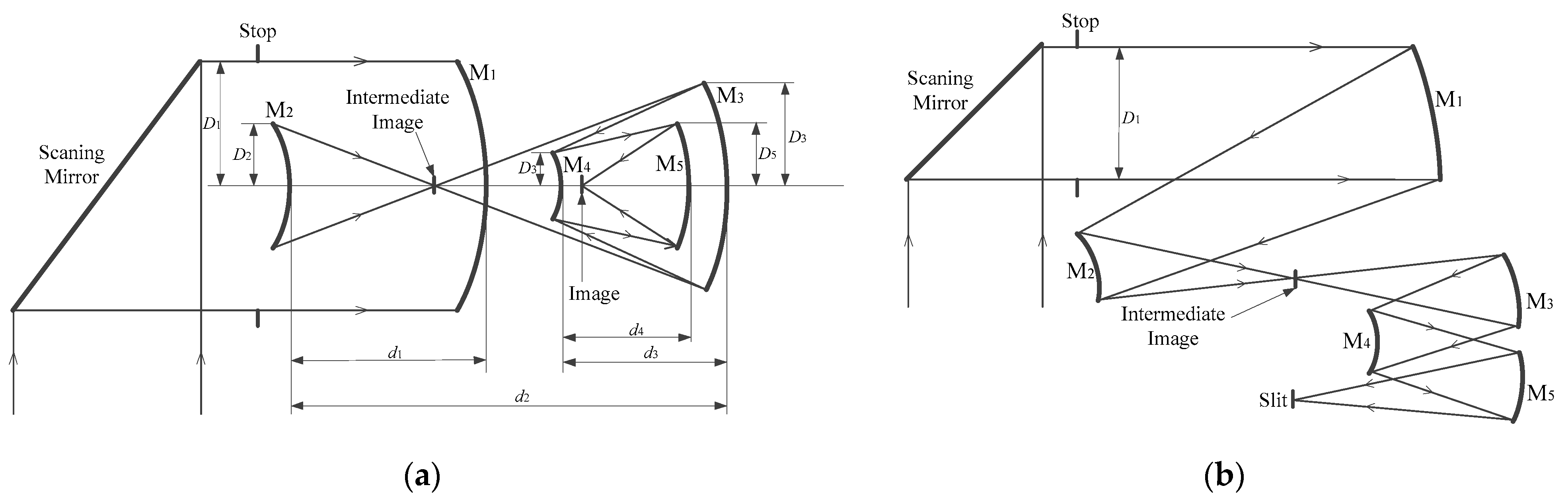
2.1. The Off-Axis Multi-Mirror Telescope System (MMTS)

The off-axis reflective optical system has the advantages of a good accessibility of large mirrors, no obstruction and no chromatic aberration [17]. In particular, the off-axis three-mirror anastigmat system (TMAS) has the advantages of a strong aberration correction ability and good telecentricity on the image side, which is widely used in the telescope systems of spaceborne imaging spectrometers such as Hyperion, EnMAP, DESIS and CHIME. With the increase in the spatial resolution of the spaceborne imaging spectrometer, the optical system has a larger aperture and small F-number. At the same time, in order to increase the integration time to meet the requirements of a high SNR, a scanning mirror is added in front of the telescope system. The telescope system needs to be designed in a such way that the size of the scanning mirror should be reduced as much as possible in order to improve the control accuracy, which requires the aperture stop to be close to the scanning mirror. The aperture stop of the traditional TMAS is located near the secondary mirror, which is far away from the scanning mirror. As the aperture and FOV of the telescope system increase, the size of the scanning mirror will increase rapidly, which is not conducive to the realization of high-precision control. Compared with the spaceborne imaging spectrometers with lower spatial resolutions, spaceborne imaging spectrometers with high resolutions have higher requirements for stray light. The intermediate image plane is an important means of suppressing the stray light of the optical system. However, the traditional TMAS does not have an intermediate image plane, and the ability of stray light suppression is limited. Aiming at the specifications of the optical system of the NGHSI and the shortcomings of the traditional TMAS, this paper proposes a new structure of an off-axis muti-mirror telescope system (MMTS) with intermediate images. The VNIR spectral band and SWIR spectral band share the common telescope system to realize the integrated design. And the two spectral bands are separated by a FOV interval of 1° and image onto the slits separately.
The MMTS offers several advantages over the traditional TMAS: (1) The aperture stop is located in front of the primary mirror and is close to the scanning mirror, thus minimizing the size of the scanning mirror and improving the control accuracy. (2) The MMTS has a real entrance pupil and an intermediate image plane, which can effectively suppress stray light. (3) The MMTS has more design variables, which means a stronger aberration correction ability, to realize the telecentric design and improve the imaging quality. Inevitably, the off-axis reflective optical system has more mirrors, which will lead to an increase in the size and weight and bring some difficulties to the processing and alignment of the optical system. However, we can realize the compact design of the off-axis reflective optical system with a reasonable layout to control the volume and the weight within an acceptable range. At the same time, with the continuous improvement of the optical processing and alignment, the engineering realization of the off-axis reflective optical system can be ensured.
A simpler way to obtain the initial structure of the off-axis MMTS is to solve the coaxial MMTS initial structure firstly. Then, the off-axis MMTS evolves from the coaxial MMTS by biasing the FOV and aperture. The initial structure of the coaxial MMTS with an intermediate image is shown in Figure 1a, consisting of the primary mirror (M1), the secondary mirror (M2), the tertiary mirror (M3), the fourth mirror (M4) and the fifth mirror (M5). The intermediate image plane is located between M2 and M3. The initial structure parameters of the coaxial MMTS with smaller aberrations can be obtained by reasonably controlling the obstruction ratio (α), angular magnification (β) and conic coefficient (k). The initial structure of the off-axis MMTS is obtained by biasing the FOV and aperture, as shown in Figure 1b, which is used as the basis of the optimized design session. By reasonably optimizing parameters such as the radius, spacing between the mirrors, decenter and tilt of five mirrors, a good aberration correction effect will be achieved.

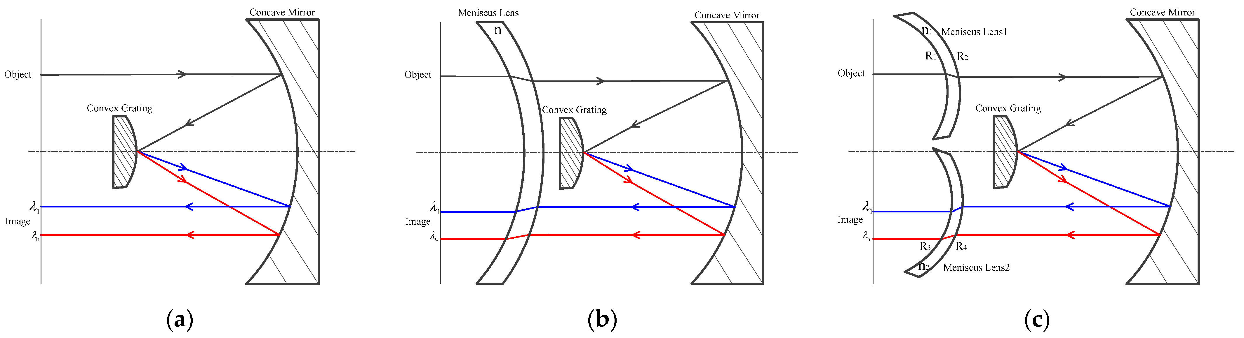
2.2. The Off-Axis Lens-Compensated Offner Spectral Imaging System

The spectral imaging system of the spaceborne imaging spectrometer usually adopts the Offner structure, such as DESIS, EnMAP, HyspIRI, ELOIS and CHIME. The classical Offner spectral imaging system consists of a concave mirror and a convex diffraction grating [18,19], shown in Figure 2a. The object plane and image plane are located in the same plane and are perpendicular to the optical axis. Therefore, the classical Offner spectral imaging system has high telecentricity on both the object and image side, so the aberrations are eliminated so that the smile and the keystone can be negligible. The radius (ho) of the perfect imaging range of the classical Offner spectral imaging system satisfies the following equation:
R M 2 4 R G 2 + h o 2 R M 2 = 1
where RM and RG are the radius of curvature of the concave mirror and convex diffraction grating, respectively.
Due to the insufficient design variables and poor aberration correction capability, the perfect imaging range of the classical Offner spectral imaging system is very small, and therefore, it has only been used in early spaceborne imaging spectrometers such as Hyperion, with a slit length of only 7.65 mm. When the slit length exceeds the perfect imaging range, the telecentricity of the classical Offner spectral imaging system will decrease, and the smile and keystone increase significantly. In order to expand the perfect imaging range, the Wynne–Offner spectral imaging system was developed on the basis of the classical Offner spectral imaging system [20], which incorporates a meniscus in front of the convex diffraction grating, shown in Figure 2b. The Wynne–Offner spectral imaging system satisfies the telecentricity condition at two different off-axis positions, and increases the slit length that can be imaged perfectly to 60 mm. The slit length of the NGHSI reaches 144 mm, which is 18 and 6 times longer than that of the on-orbit imaging spectrometers Hyperion and EnMAP [21], respectively, and 3 and 1.6 times longer than that of the in-development imaging spectrometers HyspIRI and CHIME, respectively. The slit length greatly exceeds the perfect imaging ranges of the classical Offner spectral imaging system and the Wynne–Offner spectral imaging system. In order to realize the design of a spectral imaging system with a long slit length, this paper proposes an off-axis lens-compensated Offner configuration, which consists of two off-axis compensating lenses, a convex diffraction grating and a concave mirror, shown in Figure 2c. The off-axis lens-compensated Offner configuration adds design variables such as the radius of curvature, the decenter and the tilt of the compensating lenses, which improves the aberration correction ability, thus increasing the perfect imaging range. And at the same time, the off-axis lens-compensated Offner configuration is favorable for reducing the smile and keystone to satisfy high-fidelity design requirements.
The ratio of slit length to system length is an important symbol reflecting the compactness of a spectral imaging system. Because of the limited aberration correction capability, it is difficult for the classical Offner spectral imaging system and the Wynne–Offner spectral imaging system to realize a high ratio of the slit length to the system length. For example, the classical Offner spectral imaging system for HyspIRI has a slit length of 48 mm and a system length of 320 mm, for which the ratio of slit length to system length is only 1:6.67 [22]. The off-axis lens-compensated Offner spectral imaging system can effectively reduce the length of the spectral imaging system by reasonably selecting the lens material, optimizing the radius of curvature of the compensating lenses, and controlling the spacing of the lens and mirror. So, the off-axis lens-compensated Offner spectral imaging system can achieve a higher ratio of the slit length to the system length, realizing a miniaturized design.

2.3. Freeform Surface Aberration Correction Method

For the coaxial, rotationally symmetric optical systems, the centers of the exit pupil plane, the image plane and the field aberration plane are all located on the optical axis. Nevertheless, for the off-axis optical system, the centers of different FOV aberration planes do not coincide with each other. So, the field decentration vector is used to represent the deviation of centers of different field aberration planes with respect to the center of the image plane. In order to account for the effects of tilt and decenter perturbations on the wave aberration expansion completely, Thompson presented a vector formulation of wave aberration based on the scalar aberration theory by introducing field and aperture vectors [23,24]. The third-order vector wave aberration expression for the off-axis optical system can be expressed as follows [25]:
W = Δ W 020 ( ρ ρ ) + Δ W 011 ( H ρ ) + j W 040 j ( ρ ρ ) 2 + j W 131 j [ ( H σ j ) ρ ] ( ρ ρ ) + j W 222 j [ ( H σ j ) ρ ] 2 + j W 220 j [ ( H σ j ) ( H σ j ) ] ( ρ ρ ) + j W 311 j [ ( H σ j ) ( H σ j ) ] [ ( H σ j ) ρ ]
where H denotes a normalized vector for the field height in the image plane, ρ denotes a normalized vector describing the position in the pupil, and σ j denotes the field decentration vector. Δ W 020 is the defocus term; Δ W 011 is the tilt term. W 040 j , W 131 j , W 222 j , W 220 j and W 311 j are the three-order wave aberration coefficients for spherical aberration, coma, astigmatism, field curvature and distortion, respectively.
The effective aberration field height of surface j can be defined as
H A j = H σ j
Then, using Equation (3), we obtain the explicit third-order form of Equation (2) after collation:
W = Δ W 020 ( ρ ρ ) + Δ W 011 ( H ρ ) + j W 040 j ( ρ ρ ) 2 + j W 131 j ( H A j ρ ) ( ρ ρ ) + j W 222 j 2 + j W 220 j ( H A j H A j ) ( ρ ρ ) + j W 311 j H A j ρ = Δ W 20 ρ 2 + Δ W 11 ( H ρ ) + j W 040 j ρ 4 + j W 131 j ( H A j ρ ) ρ 2 + j W 222 j ( H A j ρ ) 2 + j W 220 j H A j 2 ρ 2 + j W 311 j H A j ρ
And then it can be derived from Equations (3) and (4) as follows:
Δ W 011 ( H ρ ) = Δ W 011 ( H A j + σ j ) ρ = Δ W 011 H A j ρ + Δ W 011 σ j ρ
where Δ W 011 σ j is a constant term. And we define A 011 = j W 011 σ j ; Equation (4) can be rewritten as
W = Δ W 020 ( ρ ρ ) + Δ W 011 H A j ρ + A 011 ρ + j W 040 j ( ρ ρ ) 2 + j W 131 j ( H A j ρ ) ( ρ ρ ) + j W 222 j 2 + j W 220 j ( H A j H A j ) ( ρ ρ ) + j W 311 j H A j ρ
Assuming that the angle between the effective aberration field vector and the aperture vector is θ, Equation (6) can be converted to Equation (7) as follows:
W = Δ W 020 ρ 2 + Δ W 011 ρ cos θ + A 011 ρ + j W 040 j ρ 4 + j W 131 j ρ 3 cos θ + j W 222 j ρ 2 cos 2 θ + j W 220 j ρ 2 + j W 311 j ρ cos θ
Off-axis optical systems usually have symmetry in the sagittal direction but not in the tangential direction, so it is difficult to realize off-axis aberration corrections in the tangential direction with conventional, rotationally symmetric spherical or aspherical surfaces. Compared to spherical and aspherical surfaces, freeform surfaces do not have rotational symmetry and have more design freedom, which is very conducive to achieving good correction of off-axis aberrations. The telescope system proposed in this paper has a large aperture, small F-number and large FOV, which is difficult for realizing the requirement of telecentricity on the image side. And the slit length of the spectral imaging system is much longer than that of on-orbit and in-development spaceborne imaging spectrometers. In order to ensure the imaging quality of the telescope system and the spectral imaging system, the freeform surfaces need to be used to improve the correction capability of the off-axis aberrations. Currently, the main parametric representations for freeform surfaces are the X-Y polynomial and Zernike polynomial [26,27]. The X-Y polynomial is the same as the expression of computer numerical control (CNC) machines, which are convenient to be processed by CNC machines and have the advantages of high machining accuracy and a short machining cycle. So, the X-Y polynomial is especially suitable for the use of metal-based mirrors [28]. Meanwhile, the X-Y polynomials can select the number of terms according to the rotational symmetry of the optical system, which is conducive to improving the optimization design efficiency without reducing the degree of freedom and aberration correction capability. Therefore, this paper adopts the X-Y polynomials for the characterization of the freeform surfaces in the telescope system and the spectral imaging system. The expression of the X-Y polynomial is as follows [29]:
Z = c ρ 2 1 + 1 ( 1 + k ) c 2 ρ 2 + A m n X m Y n
where Z is the sag of the optical surface in the z-axis direction, c is the vertex curvature, ρ is the radial coordinate, k is the conic coefficient, Amn is the polynomial coefficients and XmYn is the polynomial expression terms.
In order to better analyze the relationship between the X-Y polynomial freeform surface and the aberration of the optical system, we convert the Cartesian coordinate of the X-Y polynomial freeform surface to a polar coordinate in the following equation:
X = ρ sin θ , Y = ρ cos θ
where θ is the polar angle.
According to Equations (7) and (9), the conversion relationship between the third-order aberration of the off-axis optical system and the coefficients of the X-Y polynomial freeform surface is analytically obtained, as shown in Table 2 below. The third-order aberrations and high-order aberrations of the optical system can be corrected by optimizing the coefficients of the X-Y polynomial freeform surface, which achieves good imaging quality for the optical system.
In order to ensure the feasibility of X-Y polynomial freeform surfaces for machining and inspection, it is necessary to control the maximum sag and steepness of the freeform surface deviation from the base sphere. Therefore, the highest six orders of X-Y polynomial coefficients are usually chosen, which the sum of m and n is less than six.

3. System Design and Analysis

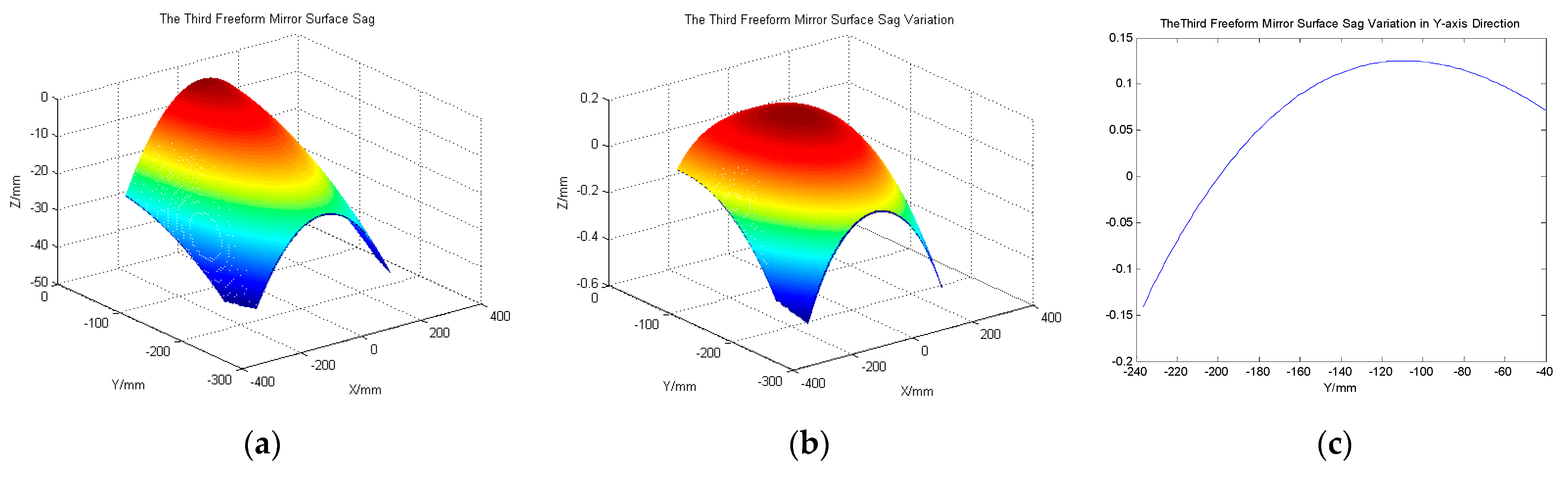
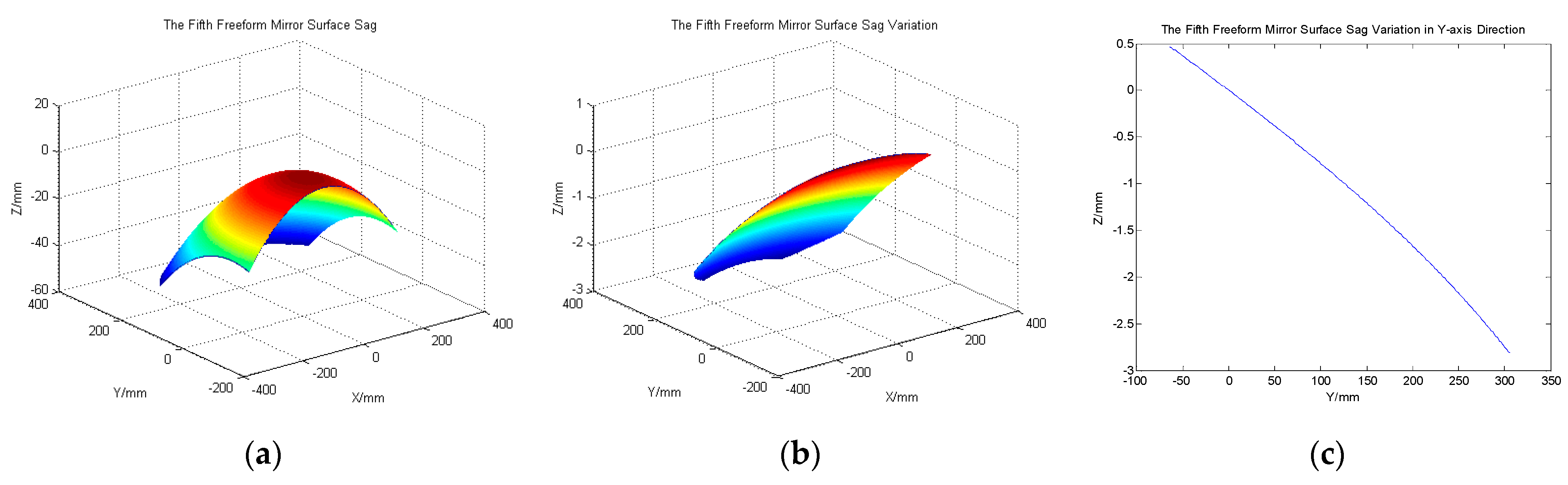
3.1. Telescope System Design and Analysis

In order to improve the aberration correction ability of the telescope system, the tertiary mirror (M3) and the fifth mirror (M5) use the X-Y polynomial freeform surfaces. And due to the rotational symmetry of the telescope system in the sagittal direction, we only use the X2mYn terms of the X-Y polynomials in the design process of optimization, which improves the optimization design efficiency. On the basis of the initial structure of the off-axis MMTS, parameters such as the vertex curvature radius, mirror spacing, X-Y polynomial coefficients, decenter and tilt of five mirrors are optimized. In order to realize the favorable telecentricity on the image side, it is necessary to ensure that the stop is located near the focal plane of the optical system on the object side. During the optimization process, we take the position of the stop as a variable to be optimized, along with other variables. The telecentricity on the image side of the telescope system is usually evaluated by the incidence angle of the chief ray of the marginal FOV in the image plane, and the smaller the angle of incidence is, the higher the telecentricity of the telescope system is. We use the incidence angle of the chief ray in the image plane as an optimization objective to reduce the incidence angle while achieving good image quality. After analyzing, the incidence angle in the image plane is only 0.33° in the VNIR spectral band, and is only 0.31° in the SWIR spectral band. Therefore, the off-axis MMTS has a high degree of telecentricity on the image side, which is favorable for good pupil matching with the spectral imaging system. The optical path diagram after optimization is shown in Figure 3. The scanning mirror is close to the aperture stop to reduce the aperture. The aperture of the scanning mirror is 420.4 mm × 625.3 mm within the scanning range of 14.64°. In order to reduce the volume of the telescope system, three planar mirrors are utilized to fold the optical path and achieve a reasonable layout.
The modulation transfer function (MTF) curves of the off-axis MMTS are shown in Figure 4. The MTF values of the different FOVs at the Nyquist frequency in the VNIR spectral band are better than 0.88 at a frequency of 20.8 lp/mm, and in the SWIR spectral band, they are better than 0.80 at a frequency of 20.8 lp/mm, all of which are close to the diffraction limit of the optical system.
The sag of the X-Y polynomial freeform mirrors M3 and M5 with respect to the base sphere are analyzed, as shown in Figure 5 and Figure 6. The maximal sag of M3 deviating from the base sphere is 0.145 mm, and that of M5 deviating from the base sphere is 2.96 mm. The sags change gently, which is feasible for optical machining by CNC machines. Taylor Hobson launched the LUPHOScan 850 HD, which is designed to perform ultra-precision non-contact 3D surface form measurement of rotationally symmetric surfaces (optics) such as aspheric lenses, spheres, flats and slight freeforms. The X-Y polynomial freeform mirrors, M3 and M5, can be inspected by LUPHOScan 850 HD.

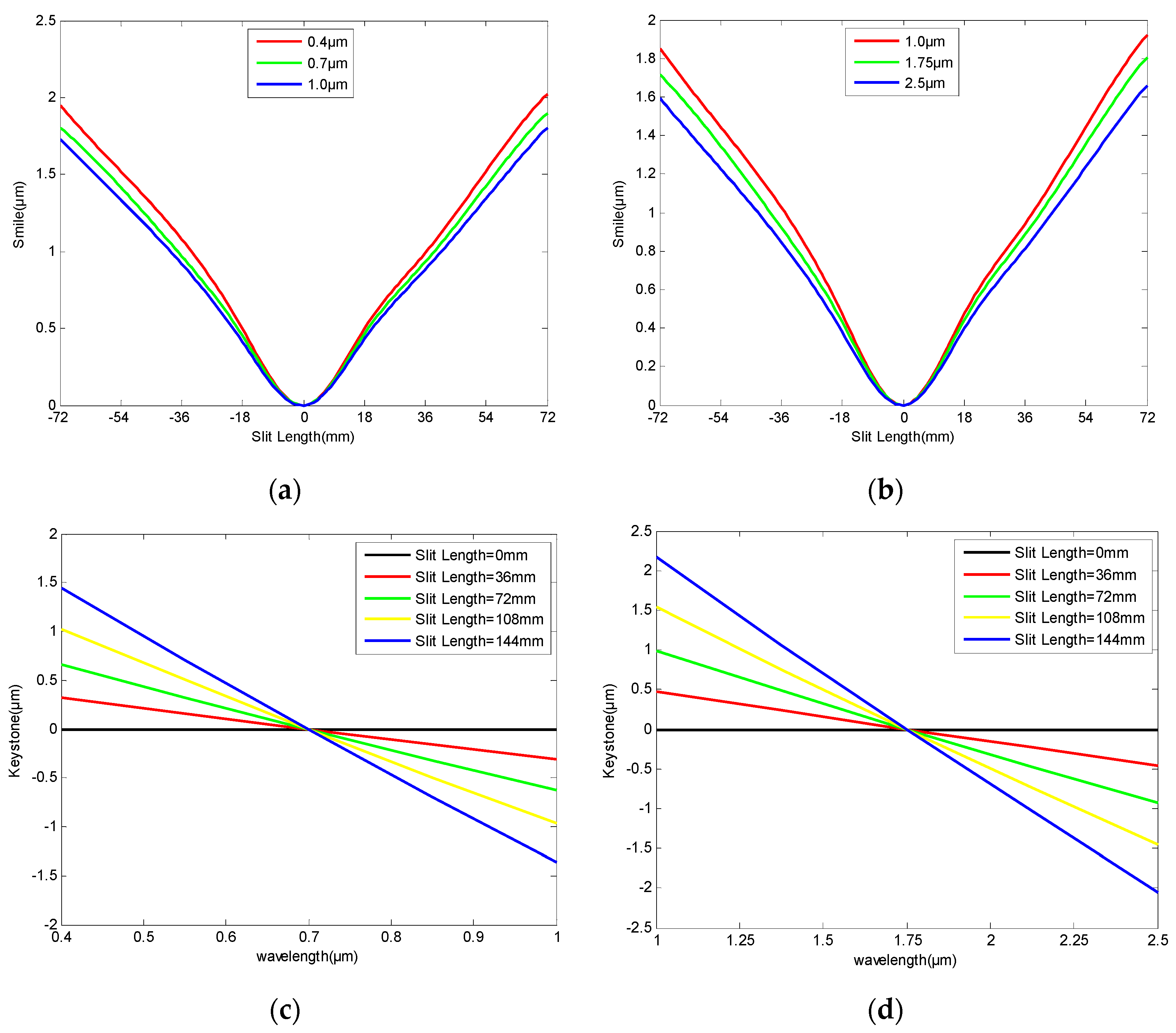
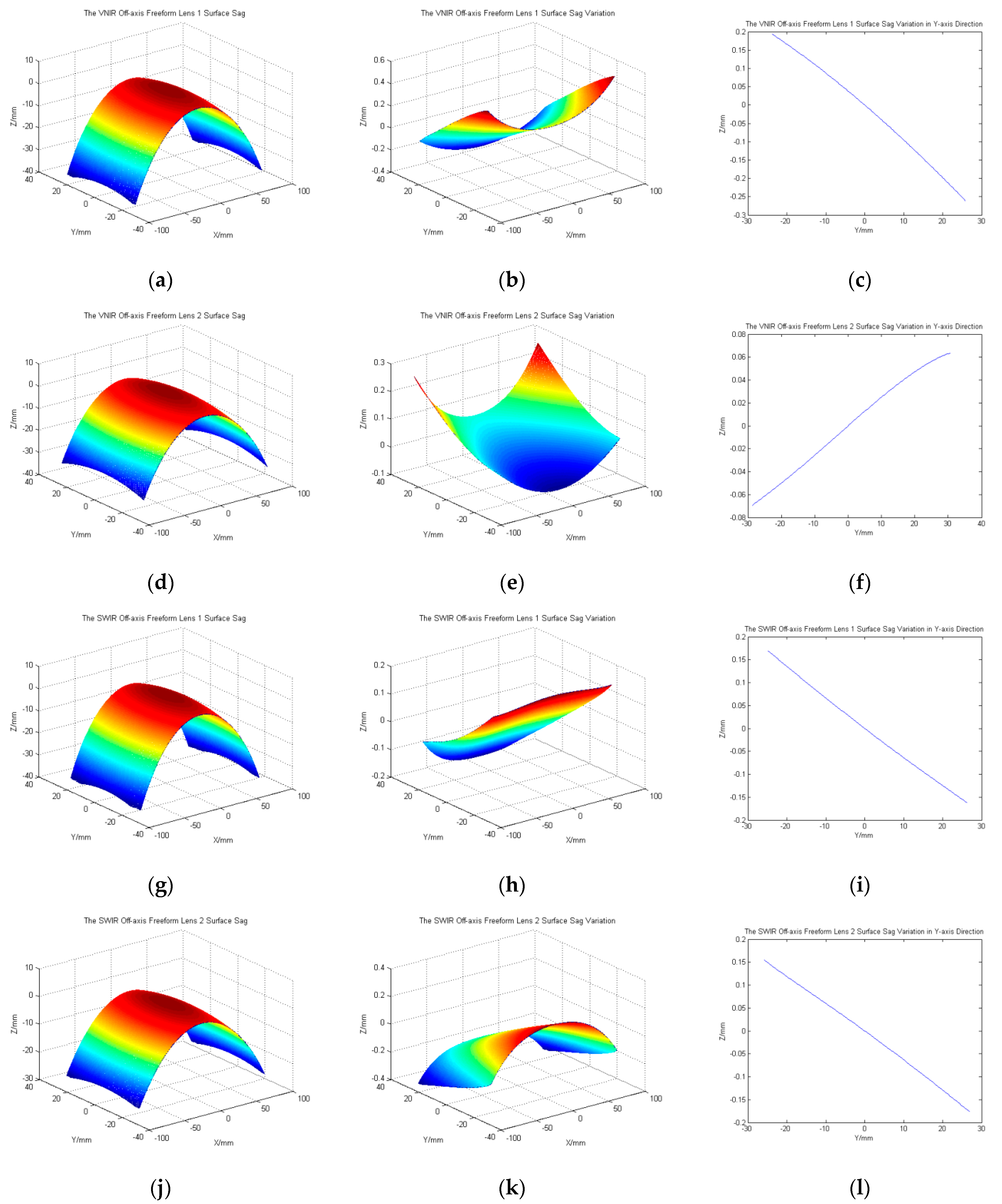
3.2. Spectral Imaging System Design and Analysis

When designing the off-axis lens-compensated Offner spectral imaging system, the length is shortened by balancing the focal power of the off-axis meniscuses and mirrors, thereby reducing the volume of the system. By adjusting the thickness, decenter and tilt of the off-axis meniscuses, we can ensure the approximate concentricity of the convex grating and mirrors that can realize the double-sided telecentric design. The higher the refractive index of the lens, the more favorable it is to realize the adjustment of the optical path difference of the incident light, thus improving the aberration correction ability of the optical system. The off-axis meniscuses L1 and L2 adopt the ZnS material, which has high transmittance in the VNIR and SWIR spectral bands and a higher refractive index compared to conventional optical glasses. And in order to improve the correction ability of marginal FOV aberrations, the front surfaces of the off-axis meniscuses, L1 and L2, adopt the X-Y polynomial. Finally, high-fidelity spectral imaging with a long slit length is realized. The optical path diagram of the optimized off-axis lens-compensated Offner spectral imaging system is shown in Figure 7. The length of the spectral imaging system in the VNIR spectral band is only 350 mm, and the ratio of the slit length to the system length is 1:2.43. The length of the SWIR spectral imaging system is only 330 mm, and the ratio of slit length to system length is 1:2.29. The off-axis lens-compensated Offner spectral imaging systems significantly reduce the system length and realize miniaturization design.
The smile and keystone in the VNIR and SWIR spectral bands are shown in Figure 8 below. The maximum smile is less than 2.05 μm in the VNIR spectral band and less than 1.92 μm in the SWIR spectral band. The maximum keystone is less than 1.48 μm in the VNIR spectral band and less than 2.22 μm in the SWIR spectral band, which are less than 1/10 pixel size, and is conducive to the improvement of the quantitative application accuracy of hyperspectral data.
The sag and deviations of the four freeform surfaces of the off-axis lens-compensated Offner spectral imaging systems in the VNIR and SWIR spectral bands are analyzed, as shown in Figure 9. The maximum sag deviation from the base sphere is 0.27 mm. The maximum sag and sag deviation are relatively small, so the freeform surfaces can be processed easily.

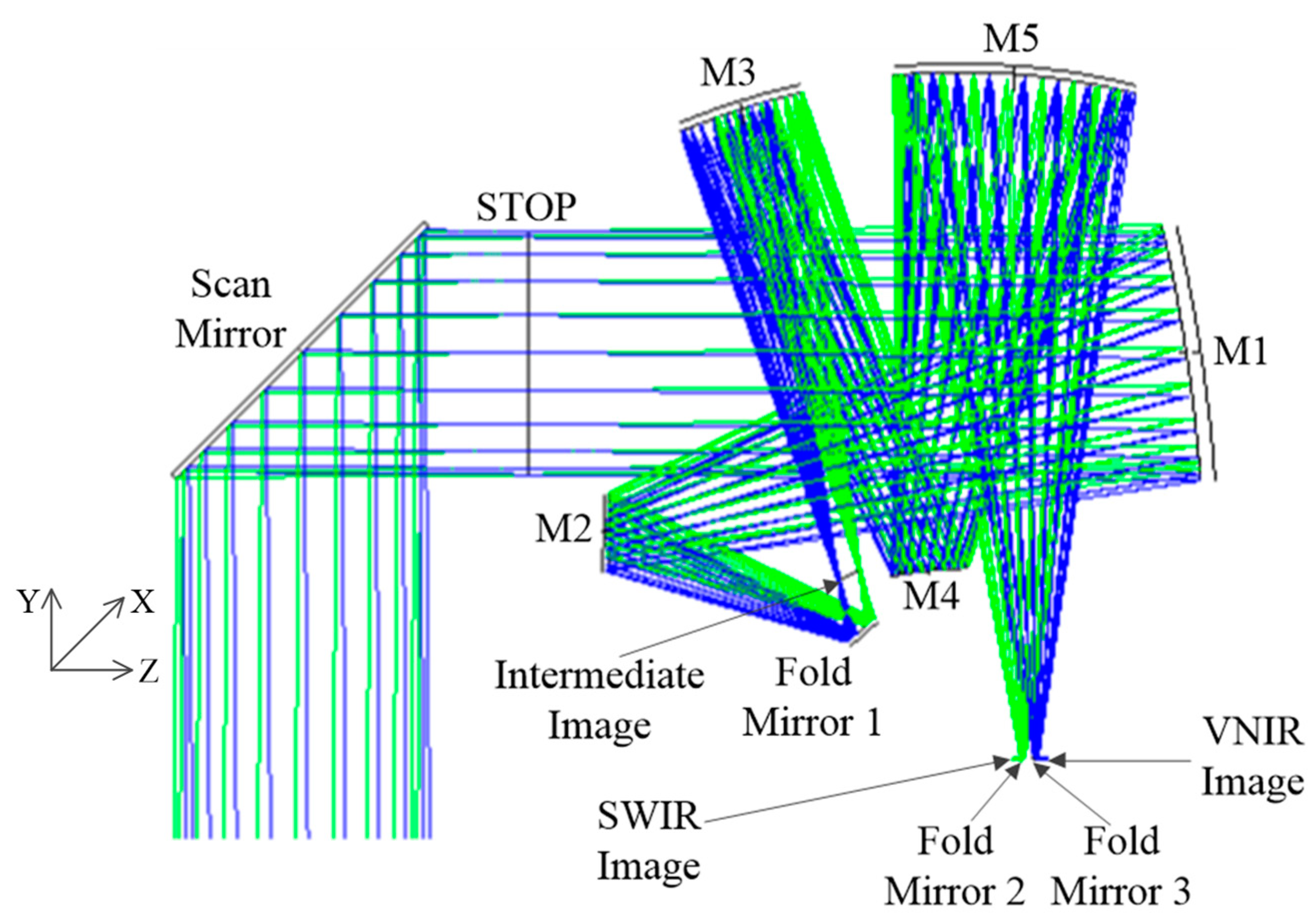
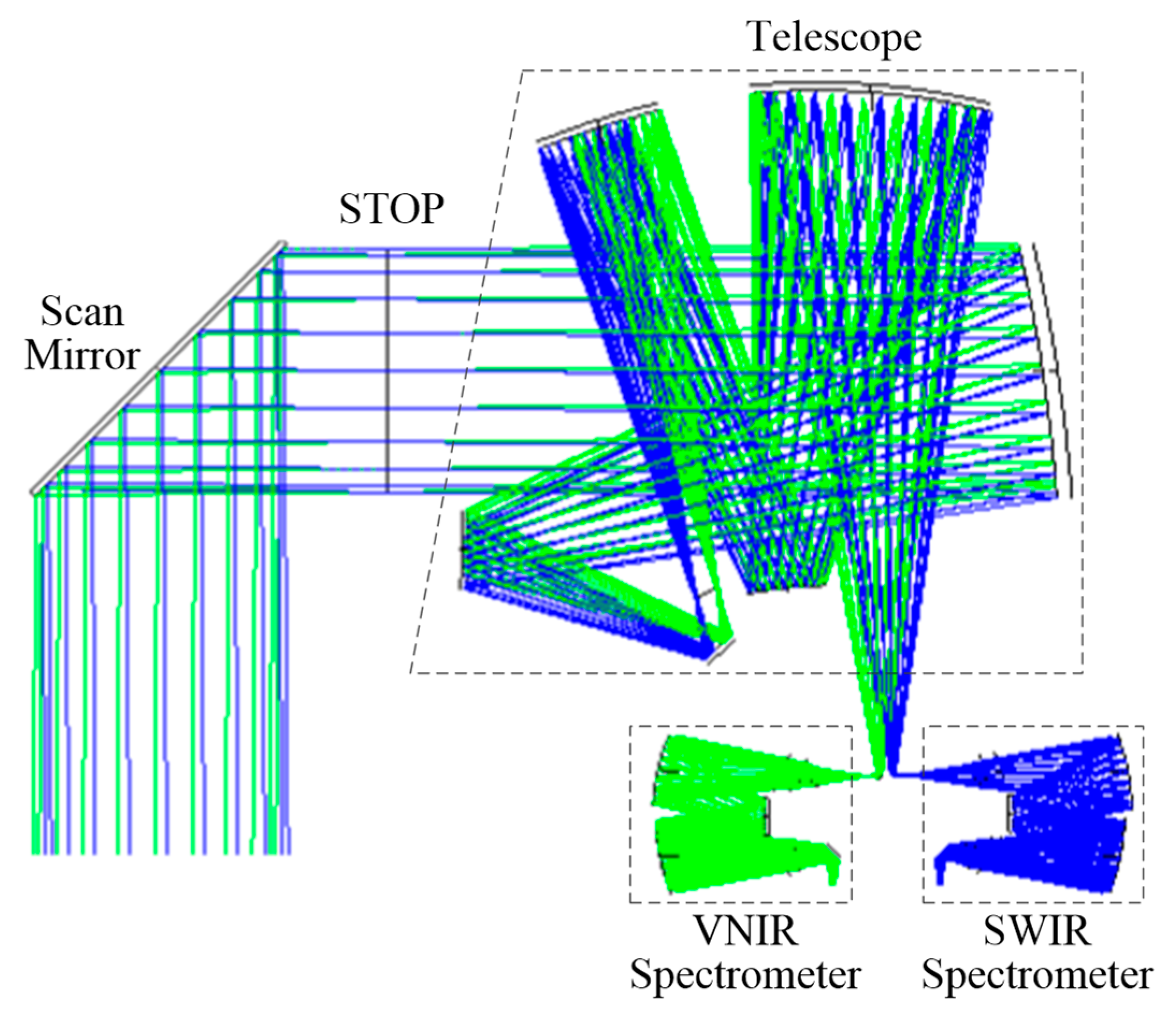
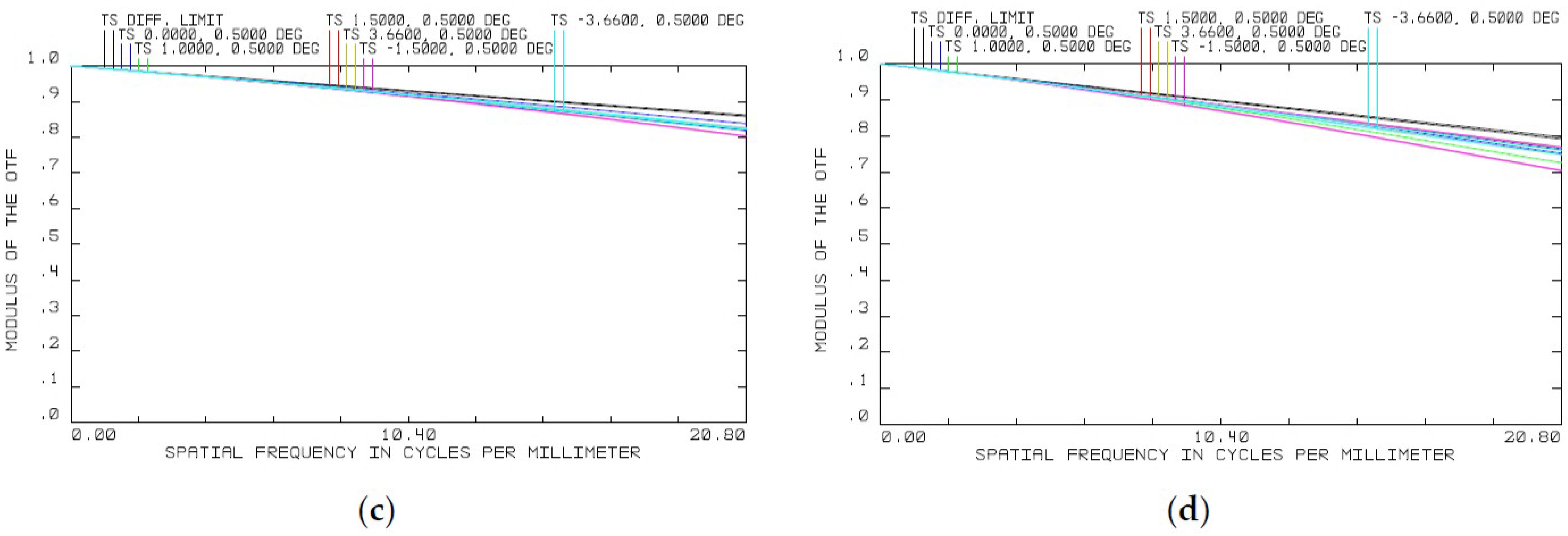
3.3. The Complete Optical System Design and Analysis

The off-axis MMTS and the off-axis lens-compensated Offner spectral imaging system connect together through the slit to form the complete optical system of the NGHSI, as shown in Figure 10. The volume of the complete system is 420 mm × 890 mm × 1700 mm (X × Y × Z); the space layout is extremely compact and reasonable.
The MTF curves of the complete optical system are shown in Figure 11, and the MTF values of different wavelengths are all greater than 0.7 at the frequency of 20.8 lp/mm. The imaging quality is excellent and can meet application requirements.

4. Discussion

The optical system of the NGHSI has a focal length of 1128 mm, an F-number of three, a field of view (FOV) of 7.32° and a slit length of 144 mm. The telescope system is characterized by a large aperture, small F-number and large FOV. Because the traditional TMAS cannot reduce the size of the scanning mirror and has a limited stray light suppression capability, the new structure of an off-axis, multi-mirror telescope system (MMTS) with intermediate images is proposed, which realizes secondary imaging and good telecentricity on the image side at the same time. The initial structure of the off-axis MMTS is received by biasing the FOV and aperture from the coaxial MMTS. By reasonably optimizing parameters such as the radius, the spacing between the mirrors, the decenter and the tilt of five mirrors, a good aberration correction effect will be achieved. In order to improve the aberration correction ability of the MMTS, the tertiary mirror (M3) and the fifth mirror (M5) use X-Y polynomial freeform surfaces. The conversion relationship between the third-order aberration of the off-axis optical system and the coefficients of the X-Y polynomial freeform surface is analyzed to establish freeform surface aberration correction method. After optimization, the MMTS has favorable imaging performance and telecentricity.
This paper proposes a new off-axis lens-compensated Offner spectral imaging system, which solves the problems of long slit length and miniaturization design. High-fidelity spectral imaging with a long slit length is realized by adjusting the thickness, decenter and tilt of the off-axis meniscuses and the use of freeform surfaces on the off-axis meniscuses, L1 and L2. Compared with the classical Offner spectral imaging system and the Wynne–Offner spectral imaging system, the Wynne–Offner spectral imaging system has a stronger imaging capability and can reduce the volume significantly. The ratio of the slit length to the system length of the off-axis lens-compensated Offner spectral imaging system is 1:2.43 and 1:2.29 in the VNIR spectral band and the SWIR spectral band, respectively.
The off-axis MMTS and the off-axis lens-compensated Offner spectral imaging system connect together through the slit to form the complete optical system of the NGHSI, as shown in Section 3.3. The volume of the complete system is 420 mm × 890 mm × 1700 mm (X × Y × Z); the space layout is extremely compact and reasonable. And the complete optical system of the NGHSI has a good imaging quality, which approaches the diffraction limit.

5. Conclusions

Based on the remote sensing application requirements of high spectral resolutions, high spatial resolutions and wide swatches, a new-generation, high-performance, space-borne hyperspectral imaging spectrometer (NGHSI) is proposed in this paper. The comprehensive performance of the spatial resolution and swatch is 1.45 times that of HyperScout-2 and 1.38 times that of CHIME, which realizes the improvement of spatial resolution and swatch at the same time. To realize the optical system design of the NGHSI, the off-axis multi-mirror telescope system (MMTS) and the off-axis lens-compensated Offner spectral imaging system are put forward. The new configuration of this optical system addresses the constraints of the simultaneous realization of high spatial resolution and wide swatch in spaceborne imaging spectrometers. And the imaging performance can meet application requirements in a variety of fields. Next, we will carry out the engineering development of the optical system by analyzing the tolerances of the mirrors and lenses and developing the programs of the optical components’ processing and optical system alignment.

Author Contributions

Conceptualization, H.J. and X.W.; software, B.W.; writing—original draft, B.W.; writing—review and editing, Y.W., C.Y. and Y.M. All authors have read and agreed to the published version of the manuscript.

Funding

This research received no external funding.

Institutional Review Board Statement

Not applicable.

Informed Consent Statement

Not applicable.

Data Availability Statement

Data are contained within the article.

Conflicts of Interest

The authors declare no conflicts of interest.

References

  1. Hank, T.B.; Berger, K.; Bach, H. Spaceborne imaging spectroscopy for sustainable agriculture: Contributions and challenges. Surv. Geophys. 2019, 40, 515–551. [Google Scholar] [CrossRef]
  2. Roth, K.L.; Roberts, D.A.; Dennison, P.E. The impact of spatial resolution on the classification of plant species and functional types within imaging spectrometer data. Remote Sens. Environ. 2015, 171, 45–57. [Google Scholar] [CrossRef]
  3. Meyer, J.M.; Kokaly, R.F.; Holley, E. Hyperspectral remote sensing of white mica: A review of imaging and point-based spectrometer studies for mineral resources, with spectrometer design considerations. Remote Sens. Environ. 2022, 275, 113000. [Google Scholar] [CrossRef]
  4. Liu, Y.M.; Ma, X.; Men, C.G. A hyperspectral remote sensing image classification method based on multi-spatial information. Chin. Space Sci. Technol. 2019, 2, 73–81. [Google Scholar]
  5. Gao, B.C.; Li, R.R.; Lucke, R.L. Vicarious calibrations of HICO data acquired from the International Space Station. Appl. Opt. 2012, 14, 2559–2567. [Google Scholar] [CrossRef] [PubMed]
  6. Mahalingam, S.; Srinivas, P.; Devi, P.K. Reflectance based vicarious calibration of HySIS sensors and spectral stability study over pseudo-invariant sites. In Proceedings of the 2019 IEEE Recent Advances in Geoscience and Remote Sensing: Technologies, Standards and Applications (TENGARSS), Kochi, India, 17–20 October 2019; pp. 132–139. [Google Scholar]
  7. Matsunag, T.; Iwasaki, A.; Tachikawa, T. The status of hyperspectral imager suite (HISUI): One year after launch. In Proceedings of the 2021 IEEE International Geoscience and Remote Sensing Symposium (IGARSS), Belgium, The Netherlands, 11–16 July 2021; pp. 1384–1385. [Google Scholar]
  8. Cogliati, S.; Sarti, F.; Chiarantini, L. The PRISMA imaging spectroscopy mission: Overview and first performance analysis. Remote Sens. Environ. 2021, 262, 112499. [Google Scholar] [CrossRef]
  9. Alonso, K.; Bachmann, M.; Burch, K. Data products, quality and validation of the DLR earth sensing imaging spectrometer (DESIS). Sensors 2019, 20, 4471. [Google Scholar] [CrossRef] [PubMed]
  10. Guanter, L.; Kaufmann, H.; Segl, K. The EnMAP spaceborne imaging spectroscopy mission for earth observation. Remote Sens. 2015, 7, 8830–8857. [Google Scholar] [CrossRef]
  11. Lee, C.M.; Cable, M.L.; Hook, S.J. An introduction to the NASA Hyperspectral InfraRed Imager (HyspIRI) mission and preparatory activities. Remote Sens. Environ. 2015, 167, 6–19. [Google Scholar] [CrossRef]
  12. Borguet, B.; Moreau, V.; Santandrea, S. The challenges of broadband performances within a compact imaging spectrometer: The ELOIS solution. Proc. SPIE 2021, 11852, 572–582. [Google Scholar]
  13. Borguet, B.; Moreau, V.; Renotte, E. The dual-blazed diffraction grating of the CHIME hyperspectral instrument: Design, modelling & breadboarding. Proc. SPIE 2023, 12777, 1041–1056. [Google Scholar]
  14. Pastena, M.; Domínguez, B.C.; Mathieu, P.P. ESA Earth observation directorate NewSpace initiatives. In Proceedings of the AIAA/USU Conference on Small Satellites, Logan, UT, USA, 3–8 August 2019. SSC19-V-05, 1-4. [Google Scholar]
  15. Hu, X.; Liao, Q.; Huang, A. High SNR eSWIR Image Sensor Applied in Advanced Hyperspectral Imager (AHSI) aboard China’s GaoFen-5 Satellite and ZY-1 Satellite. IEEE Sens. J. 2023. [Google Scholar] [CrossRef]
  16. Niu, C.; Tan, K.; Wang, X. Radiometric cross-calibration of the ZY1-02D hyperspectral imager using the GF-5 AHSI imager. IEEE Trans. Geosci. Remote Sens. 2021, 60, 1–12. [Google Scholar] [CrossRef]
  17. Wang, B.H.; Li, K.; Tang, S.F. Optical system design of a spaceborne imaging spectrometer with high resolution and super swatch. Spacecr. Recovery Remote Sens. 2021, 1, 92–99. [Google Scholar]
  18. Kwo, D.; Lawrence, G.; Chrisp, M. Design of a grating spectrometer from a 1:1 Offner mirror system. Proc. SPIE 1987, 818, 275–281. [Google Scholar]
  19. Lobb, D.R. Theory of concentric designs for grating spectrometers. Appl. Opt. 1994, 13, 2648. [Google Scholar] [CrossRef] [PubMed]
  20. Prieto-Blanco, X.; Fuente, R. Compact Offner–Wynne imaging spectrometers. Opt. Commun. 2014, 328, 143–150. [Google Scholar] [CrossRef]
  21. Stuffler, T.; Förster, K.; Hofer, S. Hyperspectral imaging—An advanced instrument concept for the EnMAP mission (Environmental Mapping and Analysis Programme). Acta Astronaut. 2009, 7–8, 1107–1112. [Google Scholar] [CrossRef]
  22. Holly, A.; Bender, P.M.; Ronald, J. Wide-field imaging spectrometer for the hyperspectral infrared imager (HyspIRI) mission. In Proceedings of the SPIE 9222, Imaging Spectrometry XIX, 92220E, San Diego, CA, USA, 15 September 2014; Volume 9222, pp. 113–120. [Google Scholar]
  23. Thompson, K.P. Description of the third-order optical aberrations of near-circular pupil optical systems without symmetry. JOSA A 2005, 7, 1389–1401. [Google Scholar] [CrossRef]
  24. Fuerschbach, K.; Rolland, J.P.; Thompson, K.P. Theory of aberration fields for general optical systems with freeform surfaces. Opt. Express 2014, 22, 26585–26606. [Google Scholar] [CrossRef]
  25. Shi, H.; Jiang, H.; Zhang, X. Analysis of nodal aberration properties in off-axis freeform system design. Appl. Opt. 2016, 24, 6782–6790. [Google Scholar] [CrossRef]
  26. Jia, B.; Li, Y.; Lv, Q. Design of a Large Field of View and Low-Distortion Off-Axis Optical System Based on a Freeform Surface. Photonics 2023, 5, 506. [Google Scholar] [CrossRef]
  27. Ye, J.; Chen, L.; Li, X. Review of optical freeform surface representation technique and its application. Opt. Eng. 2017, 11, 110901. [Google Scholar] [CrossRef]
  28. Shi, Y.; Zheng, Y.; Lin, C. Design Method of Freeform Anamorphic Telescopes with an Ultrawide Field of View. Photonics 2022, 11, 836. [Google Scholar] [CrossRef]
  29. Tan, Y.; Zhu, J. Spatial three-mirror off-axis freeform optical system without any symmetry. Photonics 2022, 9, 326. [Google Scholar] [CrossRef]
Figure 1. (a) Initial structure of coaxial multi-mirror optical system; (b) initial structure of off-axial multi-mirror optical system.
Photonics 11 00051 g001
Figure 2. (a) The classical Offner spectral imaging system; (b) the Wynne–Offner spectral imaging system; (c) the off-axis lens-compensated Offner spectral imaging system.
Photonics 11 00051 g002
Figure 3. Optical path diagram of the off-axis MMTS.
Photonics 11 00051 g003
Figure 4. (a) MTF curve of VNIR spectral band; (b) MTF curve of SWIR spectral band.
Photonics 11 00051 g004
Figure 5. (a) The sag of M3; (b) the sag deviation of M3; (c) the sag deviation of M3 in the Y-direction.
Photonics 11 00051 g005
Figure 6. (a) The sag of M5; (b) the sag deviation of M5; (c) the sag deviation of M5 in the Y-direction.
Photonics 11 00051 g006
Figure 7. (a) The VNIR off-axis lens-compensated Offner spectral imaging system; (b) the SWIR off-axis lens-compensated Offner spectral imaging system.
Photonics 11 00051 g007
Figure 8. (a) The smile in the VNIR spectral band; (b) the smile in the SWIR spectral band; (c) the keystone in the VNIR spectral band; (d) the keystone in the SWIR spectral band.
Photonics 11 00051 g008
Figure 9. The sag and deviation from base sphere of freeform surface of VNIR off-axis lens 1: (a) the sag; (b) the sag deviation; (c) the sag deviation in the Y-direction; the sag and deviation from base sphere of freeform surface of VNIR off-axis lens 2: (d) the sag; (e) the sag deviation; (f) the sag deviation in the Y-direction; the sag and deviation from base sphere of freeform surface of SWIR off-axis lens 1: (g) the sag; (h) the sag deviation; (i) the sag deviation in the Y-direction; the sag and deviation from base sphere of freeform surface of SWIR off-axis lens 2 (j) the sag; (k) the sag deviation; (l) the sag deviation in the Y-direction.
Photonics 11 00051 g009
Figure 10. Optical path diagram of the complete optical system.
Photonics 11 00051 g010
Figure 11. (a) MTF curve at 0.4 μm; (b) MTF curve at 1.0 μm; (c) MTF curve at 1.75 μm; (d) MTF curve at 2.5 μm.
Photonics 11 00051 g011aPhotonics 11 00051 g011b
Table 1. Optical system specifications of NGHSI.
ParametersSpecifications
Spectral Range0.4~2.5 μm
Spectral Resolution5 nm (0.4~1.0 μm)
10 nm (1.0~2.5 μm)
FOV7.32°
Focal Length1128 mm
Aperture376 mm
F-number3
Slit Length144 mm
Scanning Angle±7.32°
Smile≤±2.4 μm
Keystone≤±2.4 μm
Table 2. Relationship between aberration expression and X-Y polynomial.
AberrationRadial CoordinateCartesian CoordinateX-Y Polynomial Combinations
Spherical W 040 ρ 4 W 040 ( X 4 + 2 X 2 Y 2 + Y 4 ) A 40 X 4 + 2 A 22 X 2 Y 2 + A 04 Y 4
Coma W 131 ρ 3 cos θ W 131 ( X 2 + Y 2 ) Y A 21 X 2 Y + A 03 Y 3
Astigmatism W 222 ρ 2 cos 2 θ W 222 Y 2 A 02 Y 2
Field Curve W 220 ρ 2 W 220 ( X 2 + Y 2 ) A 20 X 2 + A 02 Y 2
Distortion W 311 ρ cos θ W 311 Y A 01 Y
Disclaimer/Publisher’s Note: The statements, opinions and data contained in all publications are solely those of the individual author(s) and contributor(s) and not of MDPI and/or the editor(s). MDPI and/or the editor(s) disclaim responsibility for any injury to people or property resulting from any ideas, methods, instructions or products referred to in the content.

