Article

Study of Fe:ZnSe Laser Exited by Diode Side-Pumped Er:YAG Laser

P. N. Lebedev Physical Institute of the Russian Academy of Sciences, Moscow 119991, Russia
*
Author to whom correspondence should be addressed.
Photonics 2023, 10(8), 869; https://doi.org/10.3390/photonics10080869
Submission received: 6 July 2023 / Revised: 24 July 2023 / Accepted: 25 July 2023 / Published: 26 July 2023

Abstract

:
The performance of a Fe:ZnSe laser was investigated in different schemes of excitation by a pulsed diode side-pumped Er:YAG laser. At the temperature of liquid nitrogen, the Fe:ZnSe laser, pumped by a free running 360-μs Er:YAG laser and demonstrated a pulse energy of 53 mJ with a slope efficiency of 42% relative to absorbed pump energy. When operating at room temperature, two optical schemes were considered. In the first one, the Fe:ZnSe laser crystal was pumped by a Q-switched Er:YAG laser with a passive shutter based on an additional Fe:ZnSe crystalline plate, and the cavities of both lasers were independent. In the second scheme, the cavities of the Fe:ZnSe and Er:YAG lasers were coupled, and the Fe:ZnSe crystal simultaneously served as an active element of the Fe:ZnSe laser and a passive shutter of the Er:YAG laser. Pulses with a duration of less than 200 ns and an energy of ~1 mJ were obtained from the Fe:ZnSe laser with a repetition rate of up to 50 kHz. The experimental waveforms of the laser pulses were approximated by rate equations.

1. Introduction

Fe:ZnSe laser broadly tunable in the spectral range of 3.7–5.3 μm is one of the promising mid-infrared solid-state lasers. It can operate in both pulsed and continuous-wave (CW) modes [1,2,3,4,5,6,7,8]. The CW mode was realized only at liquid nitrogen (LN) temperature, since with increasing temperature, the lifetime of the upper laser level drops due to the activation of non-radiative multiphonon recombination from 57 μs at LN temperature to 0.35 μs at room temperature (RT) and the generation threshold increases significantly. Although the operation of RT Fe:ZnSe laser was demonstrated under pumping by 300-μs pulses [9], at present, powerful nanosecond pumping pulses are mainly used when operating at RT.
Usually, a 3 μm flash-lamp pumped Q-switched Er:YAG laser serves as a source for pumping Fe:ZnSe crystals at RT. A Fe:ZnSe crystalline plate can be used as a passive Q-switcher. Firstly, such an approach has been applied in [10], where an output energy of 0.4 mJ was obtained in a Fe:ZnSe laser at RT. The pump beam was directed at a small angle (~2°) to the Fe:ZnSe laser cavity axis, that is, the cavities of the pump laser and the Fe:ZnSe laser were uncoupled. Meanwhile, a single Fe:ZnSe crystal can simultaneously serve as an Q-switcher of the Er:YAG laser and be an active element of the Fe:ZnSe laser. To do this, coupled cavities should be used.
In the first studies carried out in this direction, an Er:YLF laser with transverse pumping by a bar of laser diodes was used as a pumping laser [11,12]. The Fe:ZnSe crystal was placed in a mini-cavity tuned to a 4 μm spectral range, which, in turn, was placed inside the Er:YLF laser cavity. Nanosecond pulses with a duration of ~50 ns and an energy of up to 2 μJ were obtained. Recently we have obtained nanosecond pulses in coupled cavities of the Fe:ZnSe laser and the Er:ZrF4 fiber pumping laser [13]. An average Fe:ZnSe laser power was 63 mW with a slope efficiency of 31%. However, the Fe:ZnSe crystal was cooled with liquid nitrogen.
In this paper, we use a more powerful Er:YAG laser with a side-pumping by laser diode bars. As a result, we were able to increase the energy of a single nanosecond pulse of the RT Fe:ZnSe laser up to ~1 mJ. Mathematical simulation based on simple rate equations was used to estimate the performances of the Fe:ZnSe laser. A good agreement with experimental data was obtained.

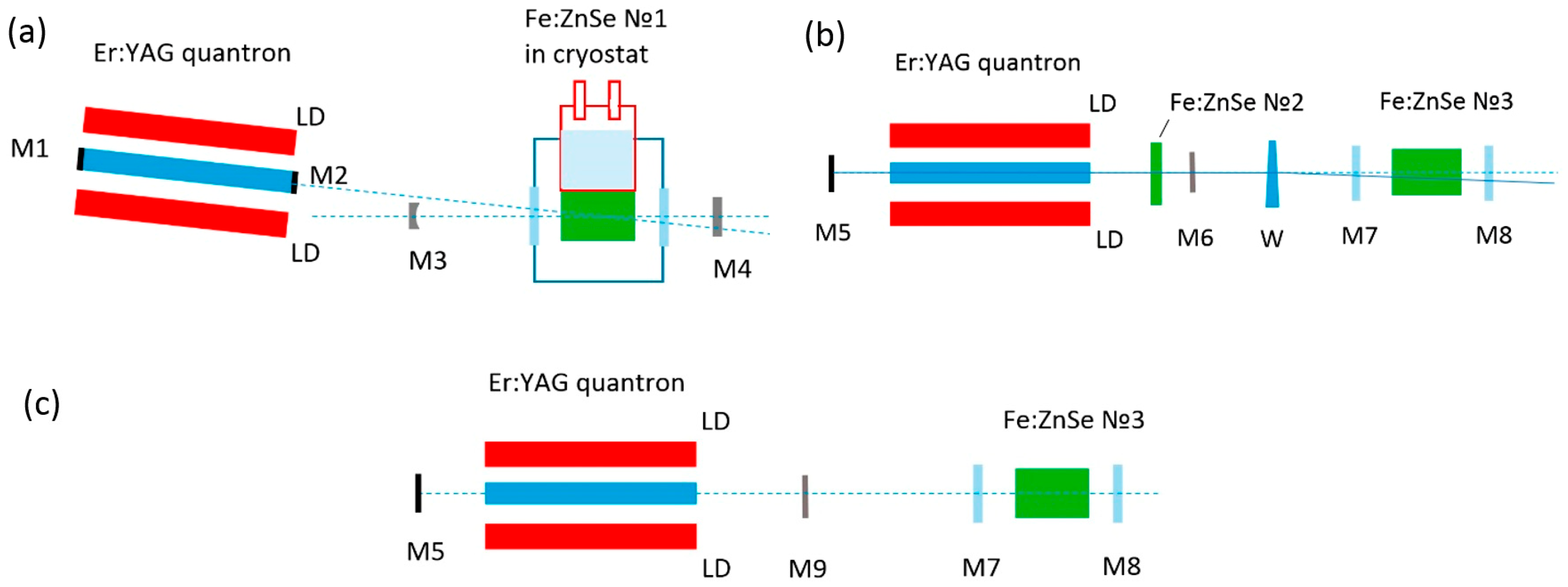
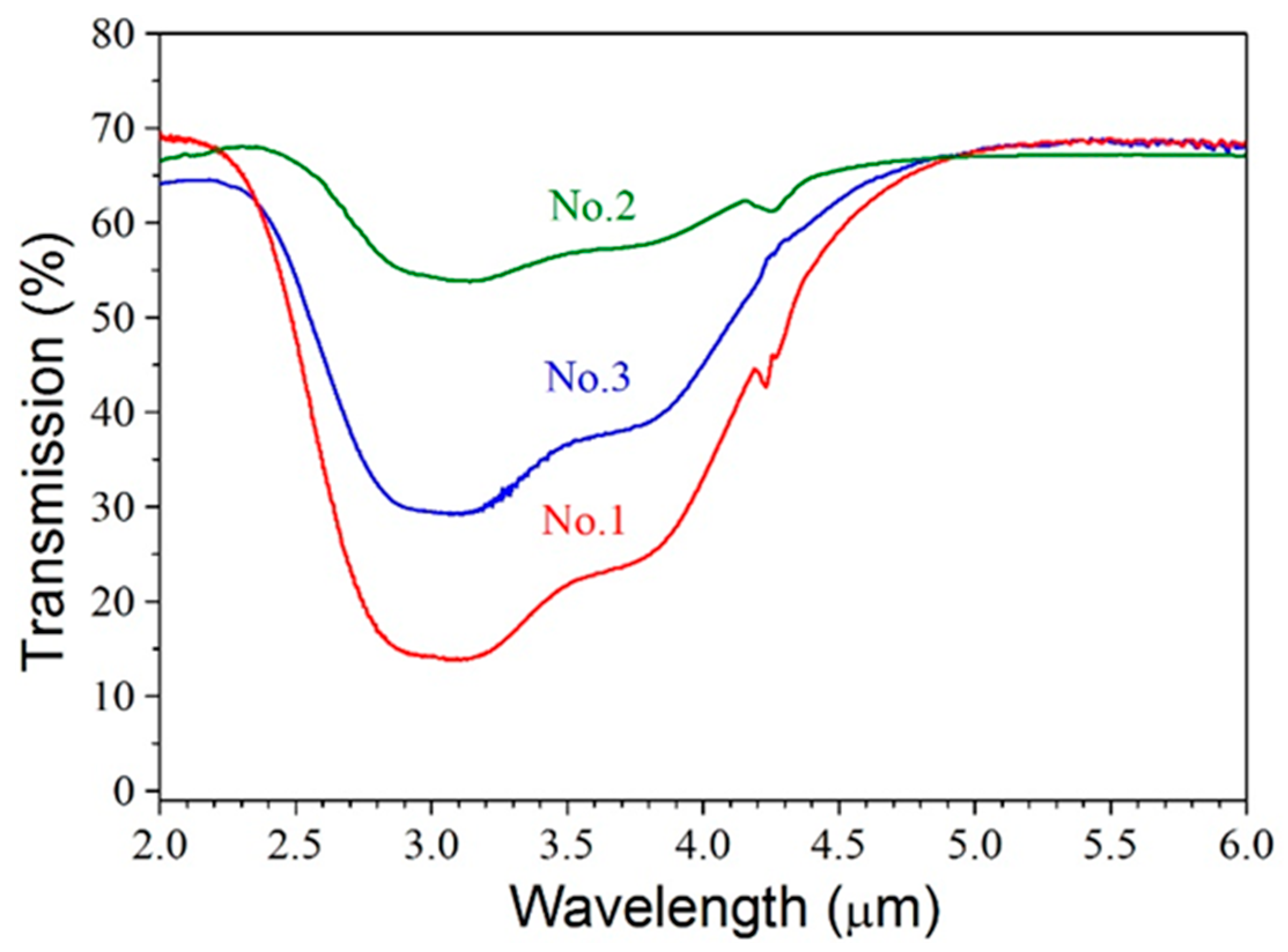
2. Materials and Methods

In this study, the Er:YAG laser was based on a diode side-pumped module developed at Lassard company. The Er:YAG (50% doping) laser rod with a length of 100 mm and a diameter of 4 mm was pumped by five laser-diode bars with a wavelength of 950 nm, connected in series to an electrical circuit. The diode bars and the rod were cooled with water using a closed-loop cooler. The diode bars were pumped with 300 μs or 360 μs current pulses, the maximum pulse repetition rate was 25 Hz. Most of the laser experiments were performed at a repetition rate of 2 Hz. Unfortunately, the emission spectra of the laser diode bars were not sufficiently consistent with the absorption spectrum of the Er:YAG rod. The best parameters of the module were achieved at a water temperature of 26–32 °C, depending on the current in the laser diodes. In this regard, the efficiency of the Er:YAG laser did not exceed 4%.
In the first series of experiments, the operation of a free-running Er:YAG laser as a pumping source of a LN-cooled Fe:ZnSe laser was investigated in the conventional optical scheme shown in Figure 1a. In this scheme, the M1 and M2 mirror coatings with reflectivity of 100% and 60%, respectively were deposited directly to the ends of the Er:YAG rod. Pumping was carried out at an angle of 3° relative to the axis of the Fe:ZnSe laser cavity. The excitation spot was approximately 3.5 mm in diameter. A plane-parallel Fe:ZnSe crystal of No. 1 with a diameter of 20 mm and a thickness of 13 mm was placed in a LN-cooled cryostat. The transmission spectrum of this crystal is shown in Figure 2. It was measured using a Fourier transform spectrometer. The Fe:ZnSe crystal No. 1 (and other Fe:ZnSe crystals used in this study) was made of a single crystal boule grown from vapor phase using a seeded physical vapor transport technique in He atmosphere [14]. Based on the measured transmission spectrum and the value of the absorption cross-section of 0.97 × 10⁻¹⁸ cm2 [2], we estimated the concentration of Fe2+ ions in the crystal No. 1 at 1.5 × 1018 cm−3. The uncoated plane-parallel CaF2 cryostat windows were aligned perpendicular to the cavity axis. The 245-mm-long cavity was formed by an aluminum spherical M3 mirror with a radius of curvature of 500 mm and a flat output M4 mirror with a transmission of 35% in the vicinity of 4 μm.
Figure 1b shows the conventional scheme used for pumping a Fe:ZnSe laser at RT by pulses of an Q-switched Er:YAG laser. In this scheme an Er:YAG rod had antireflection-coated ends, and the laser cavity was formed by the external flat M5 and M6 mirrors reflecting 100% and 90% near 3 μm, respectively. A plane-parallel crystalline Fe:ZnSe plate of No. 2 with a diameter of 25 mm and a thickness of 2.5 mm disposed between the rod and the M6 mirror was used as a passive shutter. The transmission spectrum of this plate is also shown in Figure 2. The Fe2+ ion concentration in the crystal No. 2 was estimated at 1018 cm−3. The Fe:ZnSe laser cavity was formed by the flat dichroic M7 mirror, transmitting ~95% of radiation near 3 μm and reflecting 99.5% of radiation in the vicinity of 4 μm, and the flat dichroic output M8 mirror, reflecting 99.5% of radiation near 3 μm and transmitting 75% of radiation in the vicinity of 4 μm. When the axes of the Er:YAG and Fe:ZnSe lasers were connected and a CaF2 wedge (W) was not placed between the M6 and M7 mirrors, the case of coupled cavities were realized. The M5, M6, and M8 mirrors formed a composite cavity for the Er:YAG laser. In this case, the Er:YAG laser can also operate without the M8 mirror. The M8 mirror provided a multi-pass pumping scheme of the Fe:ZnSe laser. In this regard, the Fe:ZnSe crystal of No. 3 with higher transmission at the pump wavelength was used (see Figure 2). It had a diameter of 25 mm and a thickness of 16.4 mm. The Fe2+ ion concentration in crystal No. 2 was estimated at 0.5 × 1018 cm−3.
When the CaF2 wedge (W) was placed between the M6 and M7 mirrors, it deflected the Er:YAG laser beam by 0.5° from the cavity axis of the Fe:ZnSe laser. Hence, the case of uncoupled cavities was realized. Since the angle mismatch was small, the M8 mirror provided at least two passes of pump beam through the Fe:ZnSe crystal.
In the third scheme (Figure 1c), only the Fe:ZnSe crystal of No.3 is used. The M9 mirror reflecting 60% of radiation near 3 μm had a plane-parallel substrate. The generation threshold in the Er:YAG laser was not reached when using only the M5 and M9 mirrors (without the M7, M8, and Fe:ZnSe crystal of No.3). Free-running generation of the Er:YAG laser was achieved with the Fe:ZnSe crystal of No. 3 installed (without the M7 and M8 mirrors), since the Fresnel reflection from the crystal face increased the feedback in the Er:YAG laser. With the M8 mirror installed (without the M7 mirror) the Er:YAG laser started operating in an Q-switched mode. The Er:YAG laser pulses were observed through the M8 mirror, although its transmission was small. Note that when the M9 mirror was removed, generation in the Er:YAG laser was not observed due to too high absorption in the Fe:ZnSe crystal of No. 3. The use of a composite cavity formed by the M5, M9, and M8 mirrors made it possible to reduce losses per one round trip of the cavity in the case of using Fe:ZnSe crystals with high absorption as a passive shutter. Generation in the Fe:ZnSe laser occurred only when the M7 mirror was installed and carefully adjusted. A small misalignment of the M7 mirror led to a disruption of Fe:ZnSe lasing, while the Er:YAG laser continued to operate in a Q-switched mode.
It should be noted that in this work we did not optimize the cavity configuration and used the mirrors and active crystals available to us.
The waveforms of the Er:YAG and Fe:ZnSe laser pulses were recorded by InGaAsSb PD-36 and PD-48 photodiodes (IBSG Co., Ltd., Saint Petersburg, Russia), respectively, and a digital oscilloscope (Tektronix TDS 2024B). The output energies of the lasers were measured using a PE50-SH-V2 pyroelectric energy meter with a Nova-2 display (Ophir). To estimate the energy of individual nanosecond pulse, the total energy was divided by the number of pulses taken from corresponding waveform. The laser emission spectra were recorded using a MDR-24 spectrometer (LOMO) with a diffraction grating of 300 grooves/mm. The laser beam divergency was measured using the PD-48 with a 50-μm vertical slit installed in front of its sensitive area (300 μm in diameter). This assembly was moved in a horizontal direction perpendicular to the direction of the laser beam with a step of 50 μm. The signal from the photodiode in each position was averaged over 4 pump pulses.

3. Results

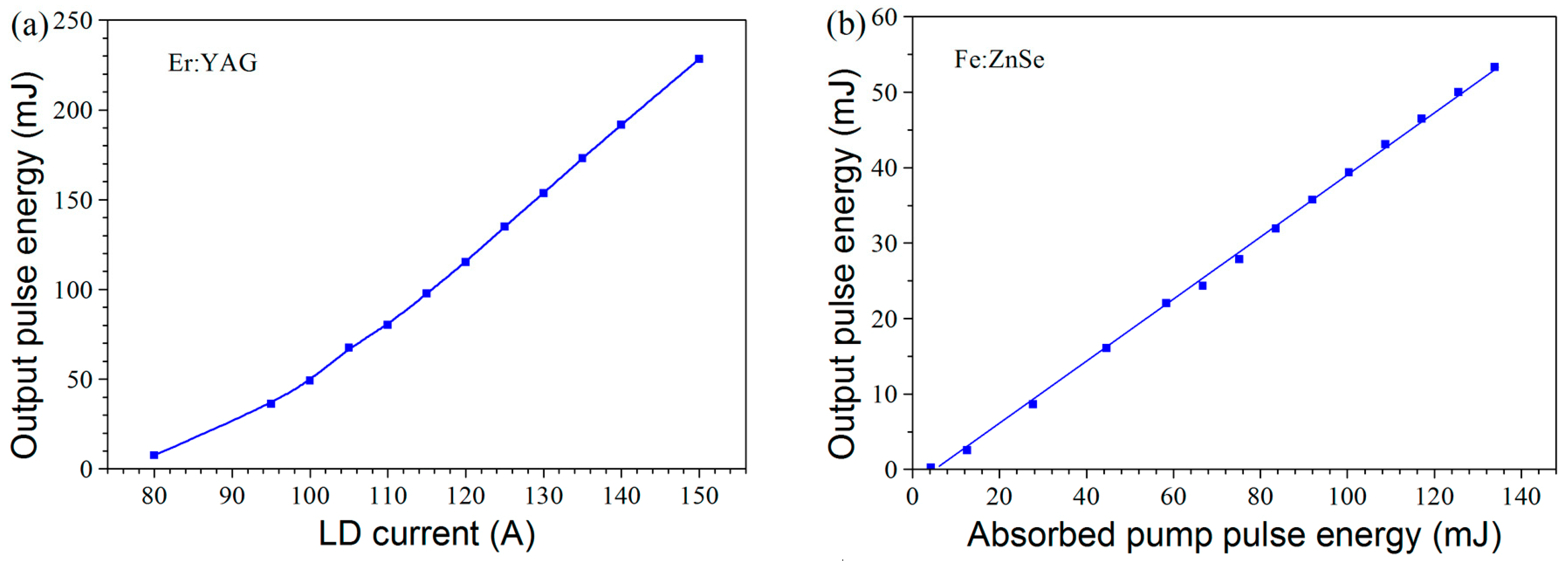
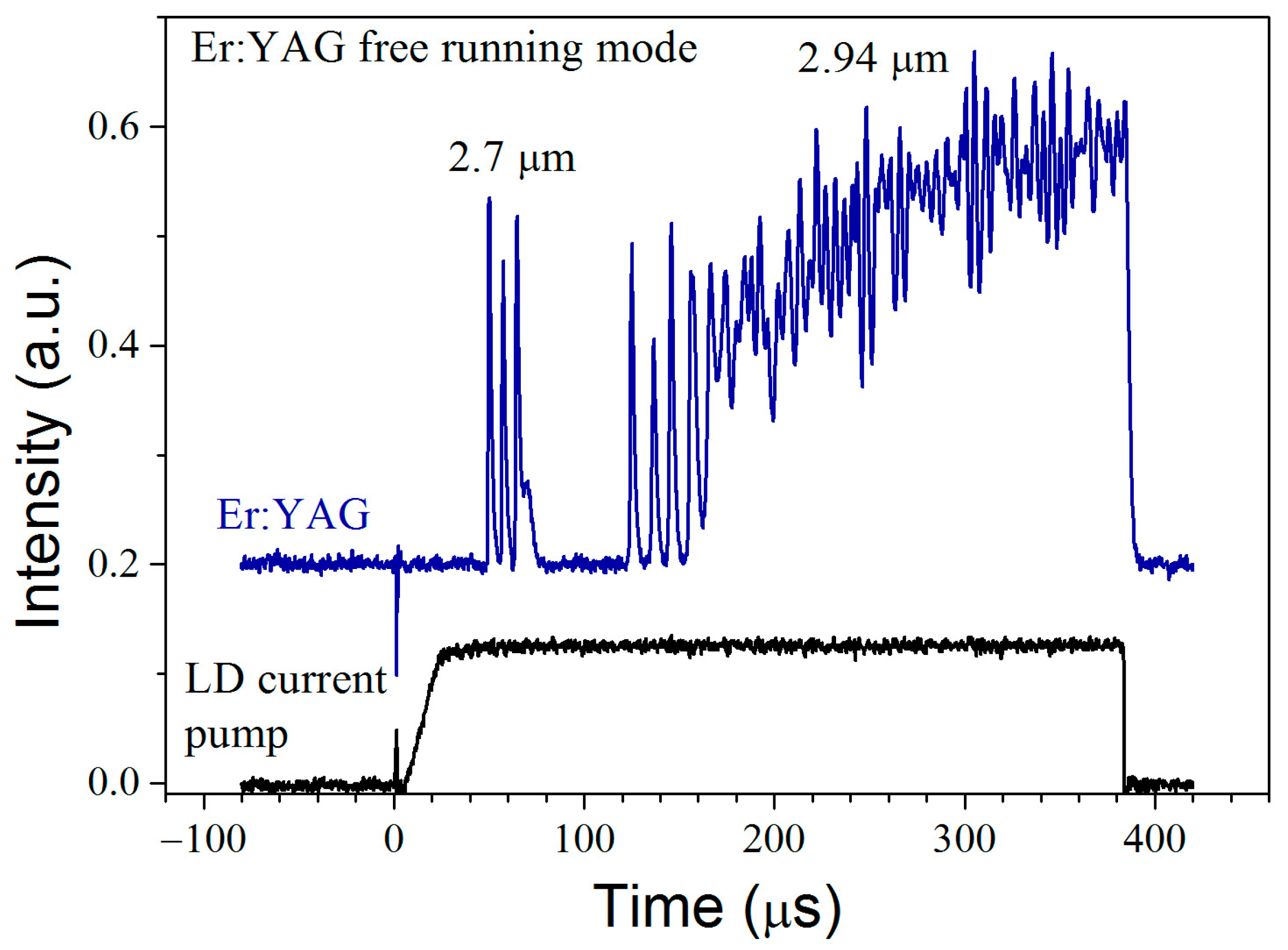
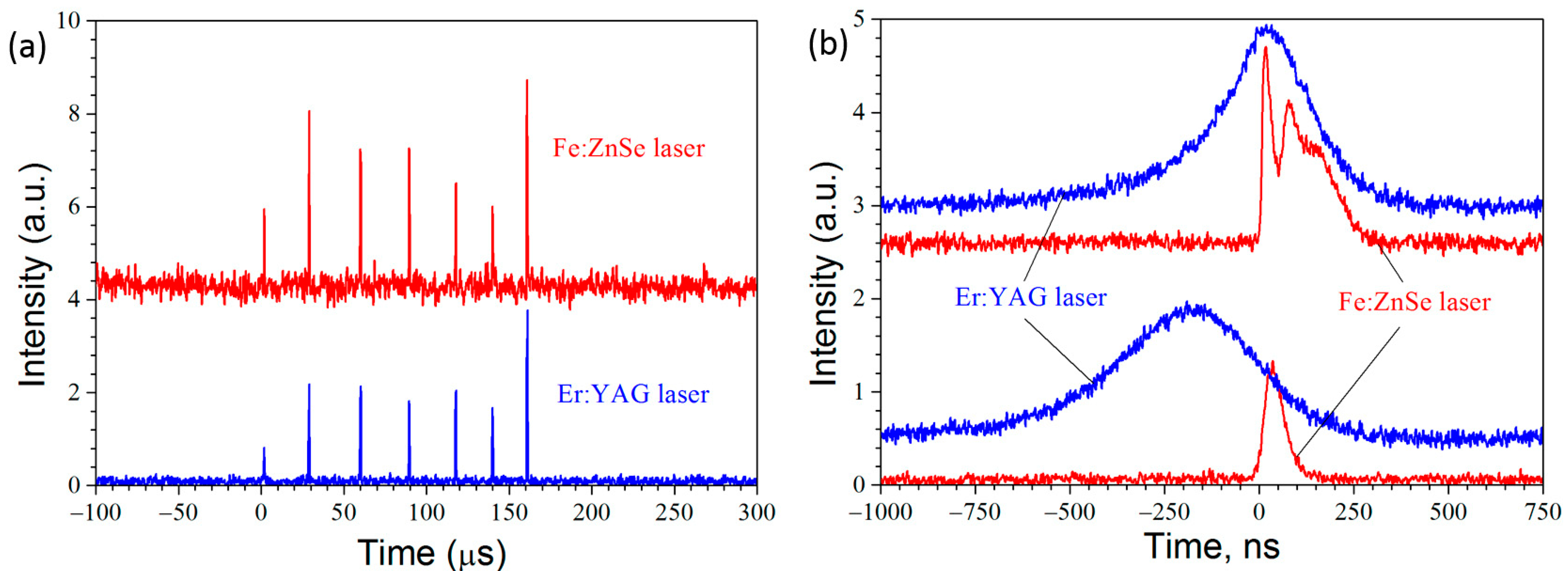
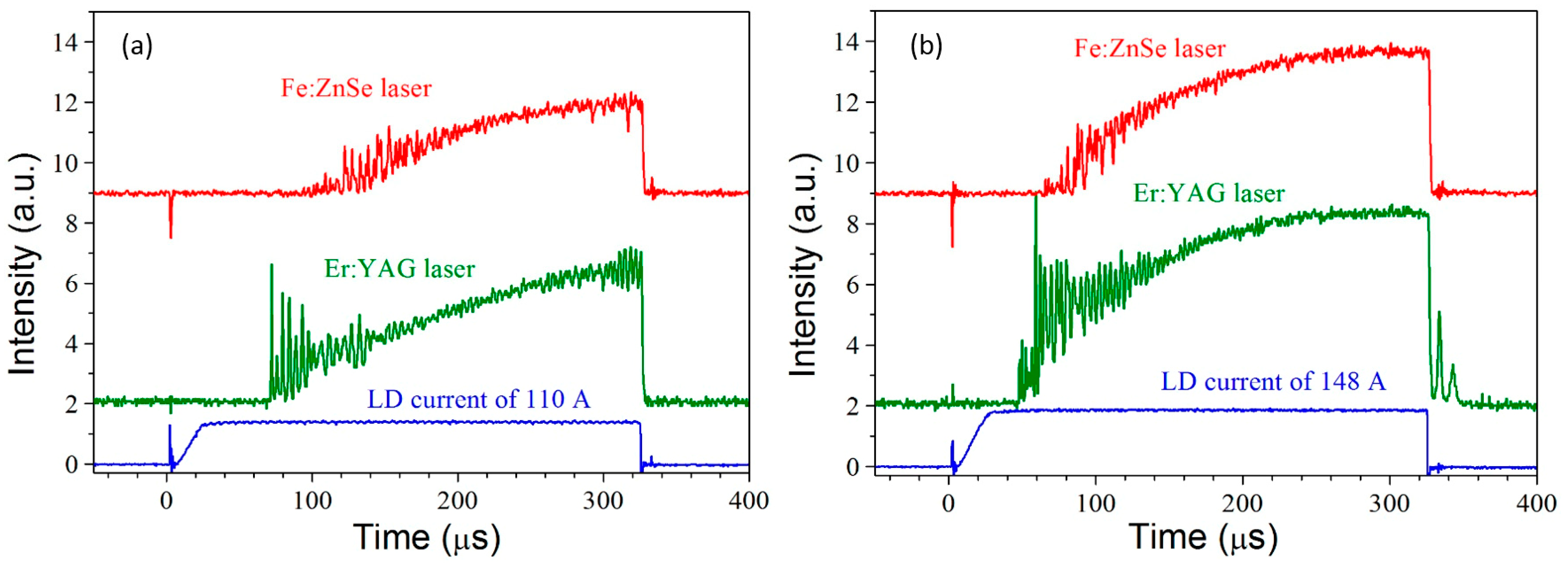
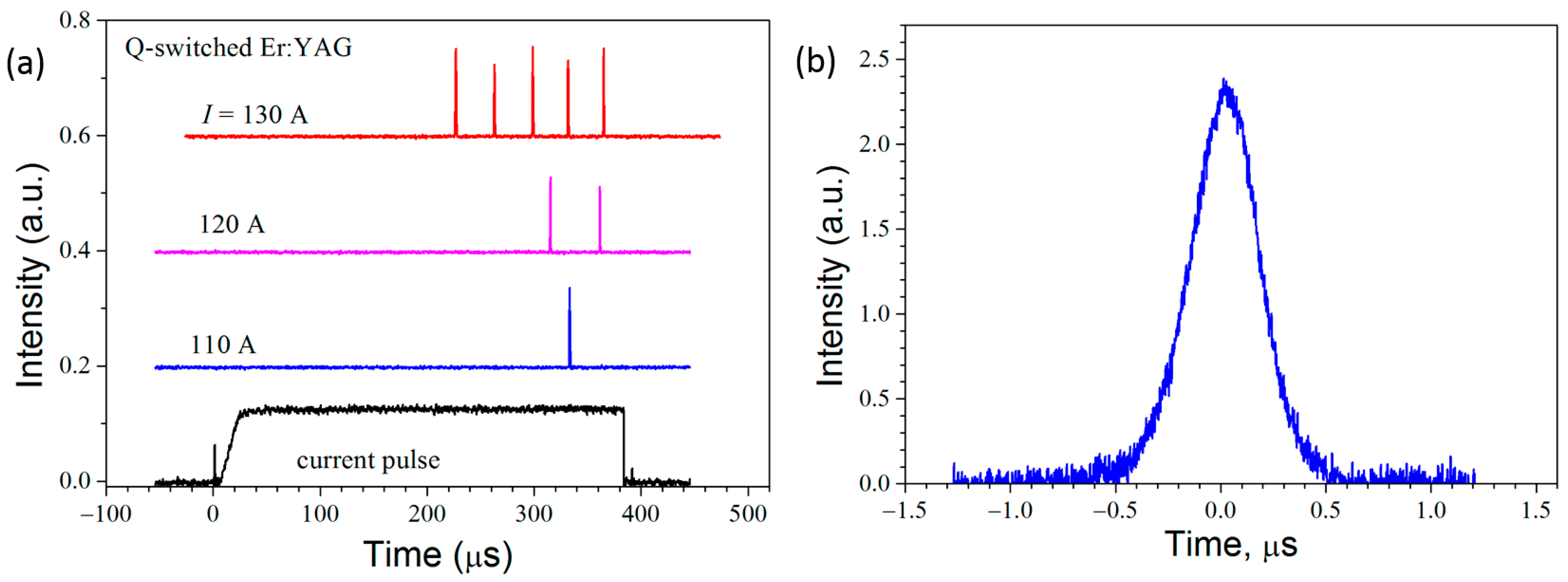
3.1. Experimental Results

Figure 3 shows the dependences of the output energy of the free-running Er:YAG laser on the current in the laser diodes and the energy of the LN-cooled Fe:ZnSe laser on the energy of the free-running Er:YAG pump laser absorbed in the crystal (scheme in Figure 1a). The absorbed pump energy was calculated by subtracting the energy reflected from the front crystal face and passed through the crystal from the incident pump energy. A pulse energy of 53 mJ was obtained at 133 mJ of pump energy with a slope efficiency of 42%. At a pulse repetition rate of 15 Hz, an average power of 0.5 W was achieved at a wavelength near 4.1 μm.
The waveforms of the free-running Er:YAG and Fe:ZnSe laser pulses together with the LD current pulse waveforms are shown in Figure 4 for two values of the LD current of 110 A and 148 A.
The pulse of the Fe:ZnSe laser is delayed relative to the pulse of the Er:YAG laser, which, in turn, is delayed relative to the beginning of the LD current pulse. These delays decrease with increasing pumping. Laser pulses have relaxation oscillations at the beginning of the pulses, characteristic of the free-running mode. The increase in the intensity of laser radiation towards the end of the pulses is probably due to the pulsed heating of the Er:YAG rod and the formation of a dynamic thermal lens. This lens in this case improves the stability of the initially unstable cavity formed by two flat mirrors.
Interestingly, when we used external mirrors for the Er:YAG laser (the scheme in Figure 1b without the Fe:ZnSe No. 2), the Er:YAG laser operates at two different wavelengths. A typical waveform of the free-running Er:YAG laser pulse is shown in Figure 5 together with a waveform of the current pulse in laser diodes. In the front part of the pulse, lasing occurs near a wavelength of 2.7 μm. Then, the spectrum shifts to a wavelength of 2.94 μm. This shift occurs faster as the pumping power increases. That is, lasing at a wavelength of 2.94 μm has more of a high threshold. A similar effect was observed earlier in the Er:YLF laser [11,12].
Figure 6a presents waveforms of the Q-switched Er:YAG laser pulses operating with the Fe:ZnSe crystal of No. 2 as a passive shutter (scheme in Figure 1b without the Fe:ZnSe crystal of No. 3 and the M7 and M8 mirrors). A typical waveform of a single spike is shown in Figure 6b. The full width at half maximum (FWHM) of such a spike is approximately 0.5 μs. The energy of a single spike did not exceed 0.7 mJ. This radiation was used to pump the Fe:ZnSe laser at RT.
In the regime of uncoupled cavities, we failed to obtain any Fe:ZnSe lasing. The excitation spot measured by burning on white paper was about 2 mm in diameter. Accordingly, the maximum pumping density was 0.023 J/cm2, which is noticeably less than the threshold density of 0.085 J/cm2 reported in [10] although they used the higher Q-factor cavity and Fe:ZnSe crystal with higher concentration of Fe ions that leads to threshold decrease. Besides, the pump pulse duration was an order of magnitude shorter.
In the regime of coupled cavities, lasing in Fe:ZnSe has been achieved. Figure 7 shows one of the waveforms of the Er:YAG and Fe:ZnSe laser pulses. Firstly, the pulse duration of the Er:YAG laser was significantly reduced, to 150 ns, compared to 500 ns (see Figure 6b). This is probably due to the inversion drop in the Fe:ZnSe crystal of No. 3 as a result of lasing. The pulse waveform demonstrates attenuating relaxation oscillations.
More stable generation in the RT Fe:ZnSe laser was achieved in a scheme with a single Fe:ZnSe crystal (see Figure 1c). Waveforms of the Er:YAG and Fe:ZnSe laser pulses are shown in Figure 8. The number of spikes (Figure 8a) increased with increasing current in the laser diodes. An average number of spikes during a pump pulse was equal to 7 at a current of 145 A. An average total energy of Fe:ZnSe laser spikes during a 360-μs pump pulse at a current of 145 A was equal to 3.2 mJ. Hence, an average spike energy was 0.46 mJ. The maximum spike energy of 1.34 mJ was achieved at a current of 155 A. This is three orders of magnitude higher than what we obtained earlier in [12]. With a spike duration of 200 ns, the energy of 1.34 mJ corresponds to a peak power of 6.7 kW. It is important to note that the generation in the RT Fe:ZnSe laser was obtained only in the regime of coupled cavities of the Fe:ZnSe and Er:YAG lasers.
Unfortunately, the instability of the output energy and the repetition rate are still too large, which is probably due to the spatial multimode generation. The minimum interval between spikes was equal to 20 μs, which corresponds to a pulse repetition rate of 50 kHz.
Emission spectrum of the Fe:ZnSe laser (scheme in Figure 1c) is represented in Figure 9. The maximum of the spectrum is near 4.4 μm and coincides with the position of maximal reflectivity of the output mirror in this spectral region.
Figure 10 shows the Fe:ZnSe laser intensity distribution at a distance of 50 mm and 350 mm from the M8 output coupler. Distributions are not described by a Gaussian function, so a multimode generation regime is implemented. Near the output coupler, the width of the diagram is approximately 2 mm at the e−1 level. It increases to 4.7 mm at a distance of 350 mm. Based on these values, it is possible to estimate the total divergency angle of 8 mrad.

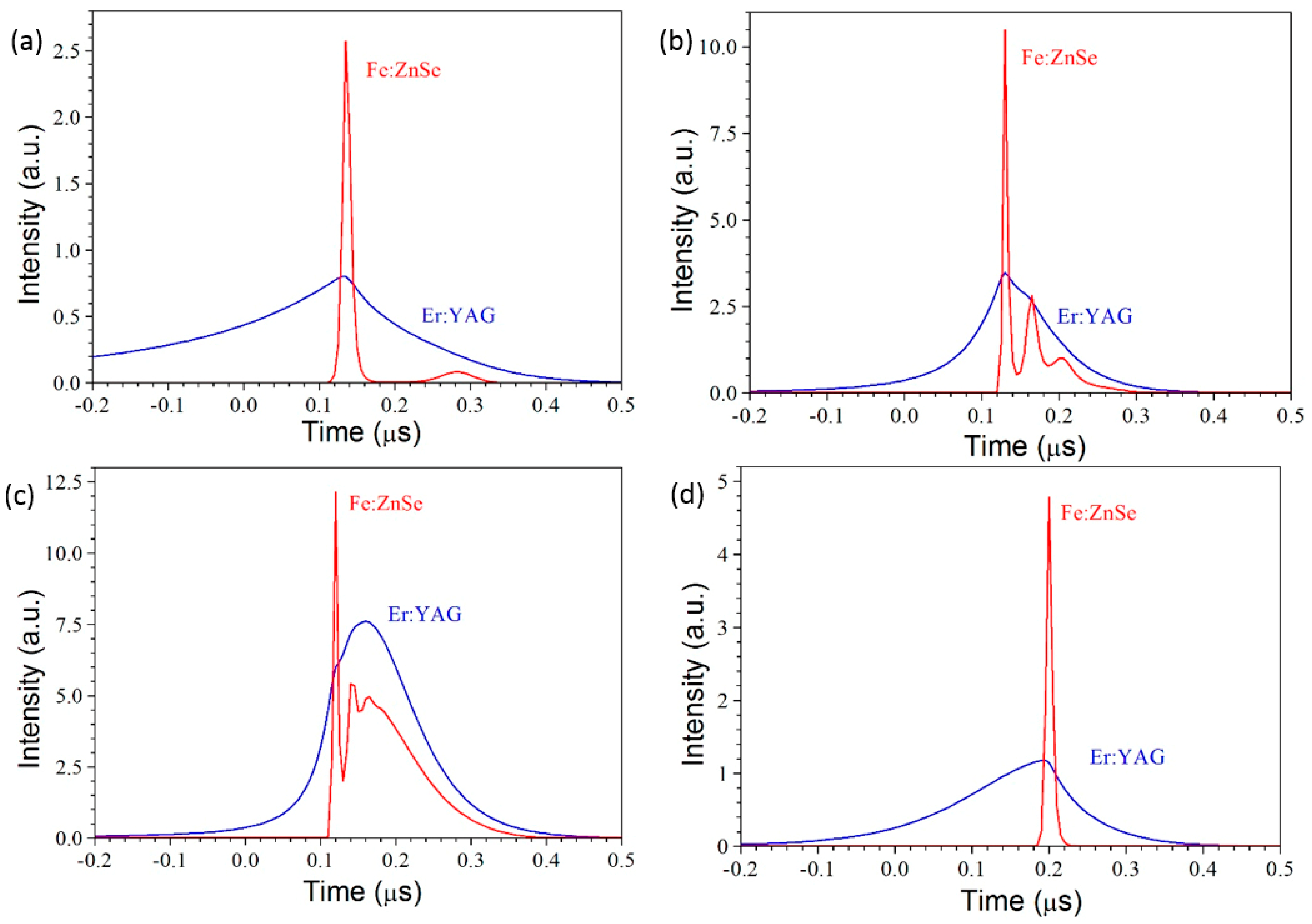
3.2. Simulation of Experimental Results

To simulate the experimental results, we used the following simplified rate equations:
d N 1 d t = N 1 · S 1 e · ρ 1 · c n 1 · L 1 L c 1 + I N 1 τ 10 ,
d ρ 1 d t = N 1 · S 1 e · ρ 1 · c n 1 · L 1 L c 1 T 1 · S 2 a · ρ 1 · N 20 N 2 · c n 2 · L 2 L c 1 ρ 1 · c · α 1 2 · L c 1 + β 1 · N 1 τ 1 ,
d N 2 d t = T 1 · S 2 a · ρ 1 · N 20 N 2 · c n 2 · L 2 L c 1 N 2 · S 2 e · ρ 2 · c n 2 · L 2 L c 2 + N 20 N 2 · S 2 e a · ρ 2 · c n 2 · L 2 L c 2 N 2 τ 2 ,
d ρ 2 d t = N 2 · S 2 e · ρ 2 · c n 2 · L 2 L c 2 N 20 N 2 · S 2 e a · ρ 2 · c n 2 · L 2 L c 2 ρ 2 · c · α 2 2 · L c 2 + β 2 · N 2 τ 20 ,
where
I = 2 · P L 1 · π · d 2 · ω · 1 + t a n h t t 1 t 0
with initial conditions
N 1 ( 0 ) = 0 ,     N 2 ( 0 ) = 0 ,     ρ 1 ( 0 ) = 0 ,     ρ 2 ( 0 ) = 0
All the data entering the rate Equations (1)–(5) are described in Table 1. The calculation was performed for scheme presented in Figure 1c. The coupling coefficient of resonators T1 is taken to be 0.35, less than the transmission of the M9 mirror equal to 0.4, since the reflection from the front face of the Fe:ZnSe crystal of No. 3 was taken into account. The equations took into account self-absorption of radiation by Fe:ZnSe crystal, which was characterized by a S2ea cross-section at 4.4 μm. It was also assumed that the rod is pumped uniformly along the radius. Since the diameter of the laser beam at the output was 2 mm and was half the diameter of the rod, the model assumed that only 25% of the pumping supplied to the rod was spent on the lasing.
The data on the emission cross section S1e of Er ion in YAG vary greatly from 0.45 × 10⁻²⁰ cm2 [16] to 2.6 × 10⁻²⁰ cm2 [17]. Figure 10 shows the calculated waveforms of the Er:YAG and Fe:ZnSe lasers for two pumping powers of 5.4 kW and 15 kW by laser diodes and three values of S1e = 0.5 × 10⁻²⁰ cm2, 1.5 × 10⁻²⁰ cm2, and 3 × 10⁻²⁰ cm2 with losses inside the resonators α1 = 0.01 and α2 = 0.3.
A comparison of Figure 8b and Figure 11 shows the qualitative agreement of the calculated waveforms with the experimental ones. At S1e = 1.5 × 10⁻²⁰ cm2 and p = 5.4 kW (Figure 10a) the Fe:ZnSe laser pulse contains one powerful spike and one weak spike. The FWHM of the Er:YAG laser pulse is approximately 300 ns. With an increase in the pumping power up to 15 kW, the number of spikes increases to 3, and their width decreases. The pulse width of the Er:YAG laser also decreases. The simulation showed a strong dependence of the shape and energy of the pulses on the parameter S1e. At S1e = 0.5 × 10⁻²⁰ cm2 Fe:ZnSe laser pulse demonstrates a sharp leading edge, relaxation oscillations, and smooth attenuation. The energy of the pulse increases. When the emission cross-section of the Er:YAG laser increases to S1e = 3 × 10⁻²⁰ cm2, the Fe:ZnSe laser pulse contains only one spike with a width of 10 ns. The energy in the spike drops, although the pulse repetition rate increases to 70 kHz.

4. Conclusions

In this study, a five laser-diode bars side-pumped Er:YAG laser module was used for excitation of Fe:ZnSe laser. Further optimization of the module will significantly increase the efficiency and average power of the Er:YAG laser compared to the flash lamp pumped one.
The use of a diode-pumped free-running Er:YAG laser as a pump source for the LN-cooled Fe:ZnSe laser made it possible to obtain a pulse energy of 53 mJ with a slope efficiency of 42% and an average power of 0.5 W.
When using a crystalline Fe:ZnSe plate as a passive shutter, Er:YAG laser was launched in the Q-switched mode with the energy of output nanosecond pulses of 0.7 mJ with a pulse duration of about 500 ns. The energy of these pulses turned out to be insufficient to achieve generation in Fe:ZnSe laser at RT and longitudinal pumping.
The RT generation was obtained when the Fe:ZnSe laser cavity was placed inside the Er:YAG laser cavity and both cavities were coupled. The generation was obtained by using both one and two Fe:ZnSe crystals. The best results were obtained using one Fe:ZnSe crystal, which operated simultaneously as a passive shutter of the Er:YAG laser and as an active element of the Fe:ZnSe laser. Pulses with an energy of up to 1.34 mJ at a wavelength of 4.4 μm with a duration of no more than 200 ns and a repetition rate of up to 50 kHz within a 360 µm pump pulse were obtained. The total divergence angle of the laser beam was equal to 8 mrad. The experimental waveforms of the laser pulses are in good agreement with the waveforms calculated using simple rate equations.

Author Contributions

Conceptualization, V.K. and M.F.; methodology, S.L. and Y.S.; investigation, V.K., Y.S., Y.K., M.F., S.L. and M.B.; writing—original draft preparation, V.K.; writing—review and editing, Y.S., Y.K., M.F., S.L. and M.B. All authors have read and agreed to the published version of the manuscript.

Funding

This research was funded by the Lebedev Physical Institute of the Russian Academy of Science.

Institutional Review Board Statement

Not applicable.

Informed Consent Statement

Not applicable.

Data Availability Statement

Data available in a publicly accessible repository.

Acknowledgments

We thank V.G. Polushkin from «Engineer center of new technologies» (Ntec) for providing us an Er:YAG rod and laser mirrors.

Conflicts of Interest

The authors declare no conflict of interest.

References

  1. Adams, J.J.; Bibeau, C.; Page, R.H.; Krol, D.M.; Furu, L.H.; Payne, S.A. 4.0–4.5 μm lasing of Fe: ZnSe below 180 K, a new mid-infrared laser material. Opt. Lett. 2000, 24, 1720–1722. [Google Scholar] [CrossRef] [PubMed]
  2. Mirov, S.B.; Moskalev, I.S.; Vasilyev, S.; Smolski, V.; Fedorov, V.V.; Martyshkin, D.; Peppers, J.; Mirov, M.; Dergachev, A.; Gapontsev, V. Frontiers of mid-IR lasers based on transition metal doped chalcogenides. IEEE J. Sel. Top. Quantum Electron. 2018, 24, 1601829. [Google Scholar] [CrossRef]
  3. Fedorov, V.V.; Mirov, S.B.; Gallian, A.; Badikov, D.V.; Frolov, M.P.; Korostelin, Y.V.; Kozlovsky, V.I.; Landman, A.I.; Podmar’kov, Y.P.; Akimov, V.A.; et al. 3.77–5.05-µm Tunable Solid-State Lasers Based on Fe2+-Doped ZnSe Crystals Operating at Low and Room Temperatures. IEEE J. Quantum Electron. 2006, 42, 907. [Google Scholar] [CrossRef]
  4. Kozlovsky, V.I.; Korostelin, Y.V.; Podmar’kov, Y.P.; Skasyrsky, Y.K.; Frolov, M.P. Middle infrared Fe2+:ZnS, Fe2+:ZnSe and Cr2+:CdSe lasers: New results. J. Phys. Conf. Ser. 2016, 740, 012006. [Google Scholar] [CrossRef]
  5. Voronov, A.A.E.; Kozlovskii, V.I.; Korostelin, Y.V.; Landman, A.I.; Podmar’Kov, Y.P.; Skasyrskii, Y.K.; Frolov, M.P. A continuous-wave Fe2+:ZnSe laser. Quantum Electron. 2008, 38, 1113–1116. [Google Scholar] [CrossRef]
  6. Vasilyev, S.; Moskalev, I.; Mirov, M.; Smolsky, V.; Martyshkin, D.; Fedorov, V.; Mirov, S.; Gapontsev, V. Progress in Cr and Fe doped ZnS/Se mid-IR CW and femtosecond lasers. Proc. SPIE 2017, 10193, 101930U. [Google Scholar] [CrossRef]
  7. Mirov, S.; Fedorov, V.; Martyshkin, D.; Moskalev, I.; Mirov, M.; Vasilyev, S. High average power Fe:ZnSe and Cr:ZnSe mid-IR solid state lasers. In Proceedings of the Advanced Solid State Lasers Conference 2015 (Optical Society of America 2015), Berlin, Germany, 4–9 October 2015; p. AW4A. [Google Scholar] [CrossRef]
  8. Pushikin, A.V.; Migal, E.A.; Tokita, S.; Korostelin, Y.V.; Potemkin, F.V. Femtosecond graphene mode-locked Fe:ZnSe laser at 4.4 µm. Opt. Lett. 2020, 45, 738. [Google Scholar] [CrossRef] [PubMed]
  9. Frolov, M.P.; Korostelin, Y.V.; Kozlovsky, V.I.; Skasyrsky, Y.K. Study of room-temperature, monocrystalline Fe:ZnSe laser, pumped by high-energy, free-running Er:YAG laser. Laser Phys. 2019, 29, 085004. [Google Scholar] [CrossRef]
  10. Akimov, V.A.; Voronov, A.A.E.; Kozlovskii, V.I.; Korostelin, Y.V.; Landman, A.I.; Podmar’kov, Y.P.; Frolov, M.P. Efficient lasing in a Fe2+:ZnSe crystal at room temperature. Quantum Electron. 2006, 36, 299–301. [Google Scholar] [CrossRef]
  11. Kozlovsky, V.I.; Korostelin, Y.V.; Skasyrsky, Y.K.; Frolov, M.P. Nanosecond room-temperature Fe:ZnSe laser pumped inside the resonator of a transversely diode-pumped Er:YLF laser. Quantum Electron. 2018, 48, 686. [Google Scholar] [CrossRef]
  12. Kozlovsky, V.I.; Frolov, M.P.; Korostelin, Y.V.; Skasyrsky, Y.K. Nanosecond-pulsed RT-operating at ~4 μm Fe:ZnSe laser pumped inside the cavity of a LD side-pumped Er:YLF laser. Opt. Express 2018, 26, 24497–24505. [Google Scholar] [CrossRef] [PubMed]
  13. Leonov, S.; Frolov, M.; Korostelin, Y.; Skasyrsky, Y.; Kozlovsky, V. Gain-switched Fe:ZnSe laser pumped by a coupled-cavity Q-switched Er:ZrF4 fiber laser. Opt. Lett. 2023, 48, 2957. [Google Scholar] [CrossRef] [PubMed]
  14. Kozlovsky, V.I.; Akimov, V.A.; Frolov, M.P.; Korostelin, Y.V.; Landman, A.I.; Martovitsky, V.P.; Mislavskii, V.V.; Podmar’kov, Y.P.; Skasyrsky, Y.K.; Voronov, A.A. Room-temperature tunable mid-infrared lasers on transition-metal doped II-VI compound crystals grown from vapour phase. Phys. Status Solidi B 2010, 247, 1553–1558. [Google Scholar] [CrossRef]
  15. Basiev, T.T.; Kharikov, E.V.; Zhekov, V.I.; Murina, T.M.; Osiko, V.V.; Prokhorov, A.M.; Starikov, B.P.; Timoshechkin, M.I.; Shcherbakov, I.A. Radiative and nonradiative transitions exhibited by Er3+ ions in mixed yttrium-erbium aluminum garnets. Sov. J. Quantum Electron. 1976, 6, 796. [Google Scholar] [CrossRef]
  16. Koetke, J.; Huber, G. Infrared excited-state absorption and stimulated-emission cross sections of Er3+-doped crystals. Appl. Phys. B 1995, 61, 151–158. [Google Scholar] [CrossRef]
  17. Zharikov, E.V.; Zhekov, V.I.; Murina, T.M.; Osiko, V.V.; Tomoshechkin, M.I.; Shcherbakov, I.A. Cross-section of the 4I11/24I13/2 laser transition in yttrium-erbium-aluminum garnet crystals. Sov. J. Quantum Electron. 1977, 7, 117–119. [Google Scholar] [CrossRef]
Figure 1. Optical schemes of Fe:ZnSe laser operated at LN temperature (a) and room temperature with two (b) and one (c) Fe:ZnSe crystals: LD is a laser diode bar; M1, M2 are mirror coatings on the ends of the Er:YAG road; M3 is a total reflector of the Fe:ZnSe laser; M4 is an output coupler of the Fe:ZnSe laser; M5 is a total reflector of the Er:YAG laser; M6 and M9 are internal mirrors of a composite cavity of the Er:YAG laser; M7 is a total reflector of the Fe:ZnSe laser which is transparent in vicinity of 3 µm; M8 is a total reflector of the Er:YAG laser and an output coupler of the Fe:ZnSe laser; W is a wedge.
Photonics 10 00869 g001
Figure 2. Transmission spectra of Fe:ZnSe crystals.
Photonics 10 00869 g002
Figure 3. (a) The free-running Er:YAG laser output energy versus the laser diode current; (b) the LN-cooled Fe:ZnSe laser pulse energy versus the absorbed pulse energy of the free-running Er:YAG laser. The cavities of the lasers are uncoupled.
Photonics 10 00869 g003
Figure 4. Waveforms of the Fe:ZnSe (upper), Er:YAG (middle) laser and LD current (lower) pulses for two values of the LD current of 110 A (a) and 148 A (b) (scheme in Figure 1a, uncoupled cavities).
Photonics 10 00869 g004
Figure 5. Waveforms of the Er:YAG laser (upper) and LD current (lower) pulses (scheme in Figure 1a, uncoupled cavities).
Photonics 10 00869 g005
Figure 6. (a) Waveforms of the Q-switched Er:YAG laser pulses at different currents in laser diodes with using the Fe:ZnSe crystal of No. 2 as passive shutter (scheme in Figure 1b, uncoupled cavities), (b) the waveform of a single giant pulse.
Photonics 10 00869 g006
Figure 7. Waveforms of the Er:YAG (lower) and Fe:ZnSe (upper) laser pulses (scheme in Figure 1b, coupled cavities).
Photonics 10 00869 g007
Figure 8. Waveforms of the Er:YAG and Fe:ZnSe laser pulses during one pumping pulse with a current of 145 A (a) and waveforms of individual giant pulses (spikes) of these lasers at a current of 120 A (lower) and 155 A (upper) (b) (scheme in Figure 1c, coupled cavities).
Photonics 10 00869 g008
Figure 9. The Fe:ZnSe laser emission spectra when using the scheme in Figure 1c. The M8 mirror reflection spectrum is also presented.
Photonics 10 00869 g009
Figure 10. The Fe:ZnSe laser beam intensity distribution in the horizontal direction at the distance of 50 mm and 350 mm from the output coupler.
Photonics 10 00869 g010
Figure 11. Calculated waveforms of the Er:YAG and Fe:ZnSe laser pulses for two pumping powers of 5.4 kW (a) and 15 kW (bd), three values of S1e = 0.5 × 10⁻²⁰ cm2 (c), 1.5 × 10⁻²⁰ cm2 (a,b), 3 × 10⁻²⁰ cm2 (d) and losses inside cavities α1 = 0.01 and α2 = 0.3.
Photonics 10 00869 g011
Table 1. Parameters entering the rate Equations (1)–(5).
ParameterDescriptionValue
N1Concentration of excited Er ions
N2Concentration of excited Fe ions
N20Total concentration of Fe ions0.5 × 1018 cm−3
ρ1Photon density in the Er:YAG laser resonator
ρ2Photon density in the Fe:ZnSe laser resonator
S1eEmission cross section of Er ionsvaries
S2aAbsorption cross section of Fe ions at 2.94 μm0.97 × 10−18 cm2 [2]
S2eEmission cross section of Fe ions at 4.4 μm1.1 × 10−18 cm2 [2]
S2eaAbsorption cross section of Fe ions at 4.4 μm0.15 × 10−18 cm2 [9]
τ1The lifetime of the upper level of Er ions85 μs [15]
τ10The radiative lifetime of the upper level of Er ions5 ms [15]
τ2The lifetime of the upper level of Fe ions0.35 μs [2]
τ20The radiative lifetime of the upper level of Fe ions57 μs [2]
β1The spontaneous emission factor in the Er:YAG laser mode10−6
β2The spontaneous emission factor in the Fe:ZnSe laser mode10−6
cSpeed of light3 × 1010 cm/s
n1Er:YAG refractive index1.79
n2Fe:ZnSe refractive index2.4
PPumping power of laser diodesvaries
ω Photon energy of laser diode radiation1.3 eV
ω 1 Photon energy of Er:YAG laser radiation0.42 eV
ω 2 Photon energy of Fe:ZnSe laser radiation0.28 eV
dDiameter of Er:YAG rod4 mm
L1Length of Er:YAG rod100 mm
L2Length of Fe:ZnSe crystal16.4 mm
Lc1Resonator length of Er:YAG laser550 mm
Lc2Resonator length of Fe:ZnSe laser50 mm
α1Round-trip losses in Er:YAG laser resonator0.02
α2Round-trip losses in Fe:ZnSe laser resonator0.25
T1Coupling coefficient between resonators0.35
T2Transmission of mirror M7 at 4.4 μm0.25
t1Pump activation parameter50 μs
t0The steepness of the pumping front30 μs
Disclaimer/Publisher’s Note: The statements, opinions and data contained in all publications are solely those of the individual author(s) and contributor(s) and not of MDPI and/or the editor(s). MDPI and/or the editor(s) disclaim responsibility for any injury to people or property resulting from any ideas, methods, instructions or products referred to in the content.

