Article

Quantitative Analysis of φ-OTDR Spatial Resolution Influenced by NLM Parameters

1
School of Ocean Information Engineering, Jimei University, Xiamen 361021, China
2
School of Optical and Electronic Information, Huazhong University of Science and Technology, Wuhan 430074, China
3
School of Marine Equipment and Mechanical Engineering, Jimei University, Xiamen 361021, China
4
School of Electrical Engineering and Artificial Intelligence, Xiamen University Malaysia, Sepang 43900, Malaysia
*
Authors to whom correspondence should be addressed.
These authors contributed equally to this work.
Photonics 2023, 10(5), 529; https://doi.org/10.3390/photonics10050529
Submission received: 12 April 2023 / Revised: 29 April 2023 / Accepted: 3 May 2023 / Published: 4 May 2023
(This article belongs to the Special Issue Optical Fibre Sensing: Recent Advances and Future Perspectives)

Abstract

:
Non-local mean (NLM) can significantly improve the signal-to-noise ratio (SNR), but it inevitably reduces the spatial resolution of distributed optical fiber sensors (DFOS), which hinders its practical application and the improvement of DFOS performance. In this paper, the quantitative relationship between the signal broadening of a phase-sensitive optical time-domain reflectometer ( φ -OTDR) and the NLM parameters is analyzed to identify the cause and extent of the spatial resolution degradation. The denoising results for the mimic periodic and φ -OTDR vibration signals indicate that the signal broadening is mainly due to the similarity window size of NLM, and the signal amplitude reduction is caused by the Gaussian smoothing parameter. Compared with the reference signals, the signal broadening of the mimic and φ -OTDR signals after denoising are 2.56% and 2.74%, respectively, which is much less than the previous results. The signal amplitude is reduced by 9.25% and 13.62%, respectively. This work promotes the application of NLM and improves the performance of DFOS.

1. Introduction

Non-local means (NLM) is a widely used technique that can greatly enhance the performance of distributed fiber optic sensors (DFOS) by exploiting the similarity and redundancy in two-dimensional signals [1,2,3,4,5,6]. The basic idea of NLM is the weighted average of the similarity windows in the image. The weight of each similarity window depends on the grayscale similarity between corresponding pixels in the original and similarity window, as well as the Euclidean distance between the original and similarity window. However, its performance is more unpredictable as the signal-to-noise ratio (SNR) enhancement highly depends on the data being denoised [6]. Subsequently, many studies have reported that their image processing method (IPM) can achieve higher SNR than NLM [7,8,9,10,11,12,13,14]. However, these study results may not be objective, as most IPM parameter optimizations are based on noise levels that cannot be accurately measured in practice [5,6,15,16]. To address this issue, we proposed a signal estimation-based IPM parameter optimization method to objectively evaluate the denoising results of various IPMs on the vibration signal of a phase-sensitive optical time-domain reflectometer ( φ -OTDR) [17,18]. The evaluation results show that the denoising quality of IPMs from high to low are NLM, wavelet denoising, and Bilateral filter. Although NLM can achieve better SNR than other IPMs, it may deteriorate the spatial resolution (SR) of DFOS [6]. Therefore, various methods, such as wavelet denoising, Bilateral filter, Block Matching and 3D filtering, and video-Block Matching and 3D filtering, have been attempted to improve the SR besides the measurement accuracy (MA) [5,8,9,10]. Recent studies have shown that the SR for ideal data and original noisy data is 0.4 m, and it retains 0.4 m by Brillouin spectrum-reassembly filter, but the SR deteriorates to 1.5 m by NLM filter [19]. The combination of NLM and Gaussian filter can effectively improve the performance of the distributed Brillouin fiber sensor compared to the results obtained with NLM, enabling a 22% improvement in MA in the non-transition section and an 84% improvement in SR in the transition section [20]. Anisotropic diffusion provides better measured MA and SR than the other three methods (wavelet denoising, NLM, Block Matching and 3D filtering), but worsens the root mean square error (RMSE) in experiments [13]. Then, the asynchronous anisotropic diffusion (AAD) algorithm reduced the RMSE to a level comparable to those obtained by the other three methods, and the SRs of AAD (2.23 m, 3.25 m, and 2.71 m) are much higher than those of NLM (8.03 m, 8.64 m, and 5.24 m) at temperatures of 40 ° C, 50 ° C, and 60 ° C, respectively [14]. Moreover, the total variation deconvolution algorithm increases the SR of 40/60 ns differential pulse-width pair signals to 0.5 and 1 m [21]. The frequency domain feature filter (0.78 ° C, 8.2 m) achieves better temperature measurement uncertainty and SR for Brillouin scattering signal denoising than the NLM filter (0.84 ° C, 8.5 m) [22]. Both methods are much worse than the average of 5000 measurements (0.58 ° C and 7.8 m). Additionally, the neural network can also significantly improve both MA and SR [23,24,25], but usually requires a lengthy data training process. Some methods based on special optical fiber and structure have been used to improve the SR and MA, but the cost of special fiber itself and installation is relatively high [26,27,28]. In short, the SRs obtained by the aforementioned filters are even several times better than that of NLM, which means that the signal broadening caused by NLM parameter can be very severe. However, the cause of SR deterioration after NLM denoising has not yet been analysed and the degree of SR deterioration due to improved MA has not been quantified.
In this paper, the reason for the signal broadening of φ -OTDR is explored by quantitatively analysing the relationship between SR and the NLM parameters. Firstly, a procedure is presented to quantify the effect of the NLM parameters on the SR of φ -OTDR. Secondly, the relationship of the SR and MA with each NLM parameter is analysed based on a simulated noisy periodic signal and a measured φ -OTDR vibration signal, respectively. Lastly, the NLM parameter that has the greatest effect on signal broadening is determined, and the extent of signal broadening is evaluated when the NLM parameters are optimal. This work helps to improve the SR and MA of φ -OTDR and the performance of vibration signal recognition [29].

2. Processing Steps for Signal SR Affected by NLM Parameters

2.1. φ -OTDR Signal

The same setup and actual signal data as in previous work [17] are used to investigate the cause and extent of SR degradation of φ -OTDR signal. In this study, the first 40 m of sensing fiber is applied to an ambient weak vibration, while the remaining 60 m is kept stationary. As shown in Figure 1a, 100 adjacent backscattered light traces are subtracted from the previous one to form a two-dimensional signal. The signal broadening and amplitude of the denoised trace are expressed as the full width at half maximum (FWHM) and amplitude (AM) of the signal trace, respectively, as shown in Figure 1b. For the convenience of observation, the FWHM and AM of the denoised signal trace are scaled to those before denoising, namely, FWHM n /FWHM 0 and AM n /AM 0 .

2.2. NLM Parameters

The basic principle of NLM is to perform a weighted average of similarity windows in an image, which makes full use of redundant information to remove noise and improve image quality [30]. Despite its effectiveness, the filtering parameters of NLM, which include the Gaussian smoothing parameter (GSP), similarity window size (SIWS), and search window size (SEWS), can significantly impact the SR and MA of the denoised signal. The GSP is the width of the smoothing kernel used to remove noise and parts of signal details, which is usually set to a constant multiple of the noise level in the image. The SIWS is a smoothing kernel for weighted averaging of image patches with a size comparable to the smallest detail in the image. The SEWS is a search window that should be large enough to contain as many similarity windows as possible. Therefore, it is necessary to optimize the NLM parameters to achieve a better denoising quality of φ -OTDR signal, which can be evaluated by an indicator similar to SNR, namely, the first cycle lag of the autocorrelation function (FCL-ACF) [17]. In addition, it is important to use an objective index to evaluate the denoising quality of the denoised signal because the conventional SNR requires to accurately estimate noise level. However, it is difficult to realize in practice. Therefore, an objective assessment index, FCL-ACF, has been demonstrated to compare different image processing methods in our previous work.

2.3. Steps for Obtaining the Relationship between FWHM and NLM Parameters

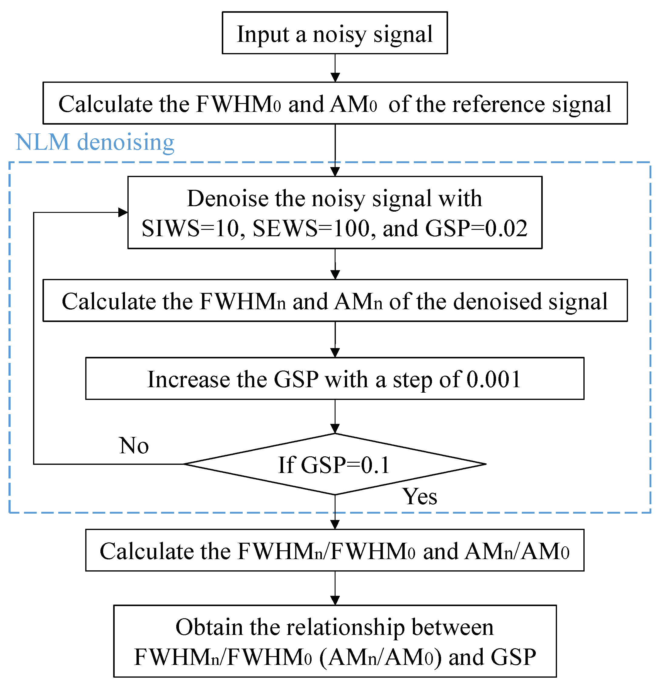
To quantify the SR of the signal, as shown in Figure 2, the signal broadening and amplitude change caused by the GSP are calculated by the following steps:
  • Input a noisy signal;
  • Calculate the FWHM 0 and AM 0 of the reference signal;
  • Denoise the noisy signal with SIWS = 10, SEWS = 100, and the GSP increasing from 0.02 with a step of 0.001;
  • Calculate the FWHM n and AM n of the denoised signal;
  • Repeat steps 3 to 4 until the GSP reaches 0.1;
  • Calculate the FWHM n /FWHM 0 and AM n /AM 0 .
As a result, the change of the signal broadening (FWHM) and amplitude (AM) of the denoised trace with the GSP can be analysed. The quantitative relationship between the SR and the other NLM parameters (SIWS and SEWS) can also be obtained by the similar processing steps. When the filter parameters are set to inappropriate values, the SNR of the filtered signal is usually very low. To accurately obtain the spatial resolution of the signals with low SNR, a sixth-order nonlinear fitting to the noisy signal is performed.

3. SR of Simulated Signals Varies with the NLM Parameters

As shown in Figure 3, a mimic clean image contaminated by noise with an amplitude of 0.2 is utilized to measure the impact of NLM parameters on the FWHM and amplitude.
f 0 = 0.3 sin 4 π 63 x sin 4 π 63 y , ( x , y ) [ 1 , 126 ]
where ( x , y ) is the pixel position of the image.

3.1. FWHM Varies with NLM Parameters

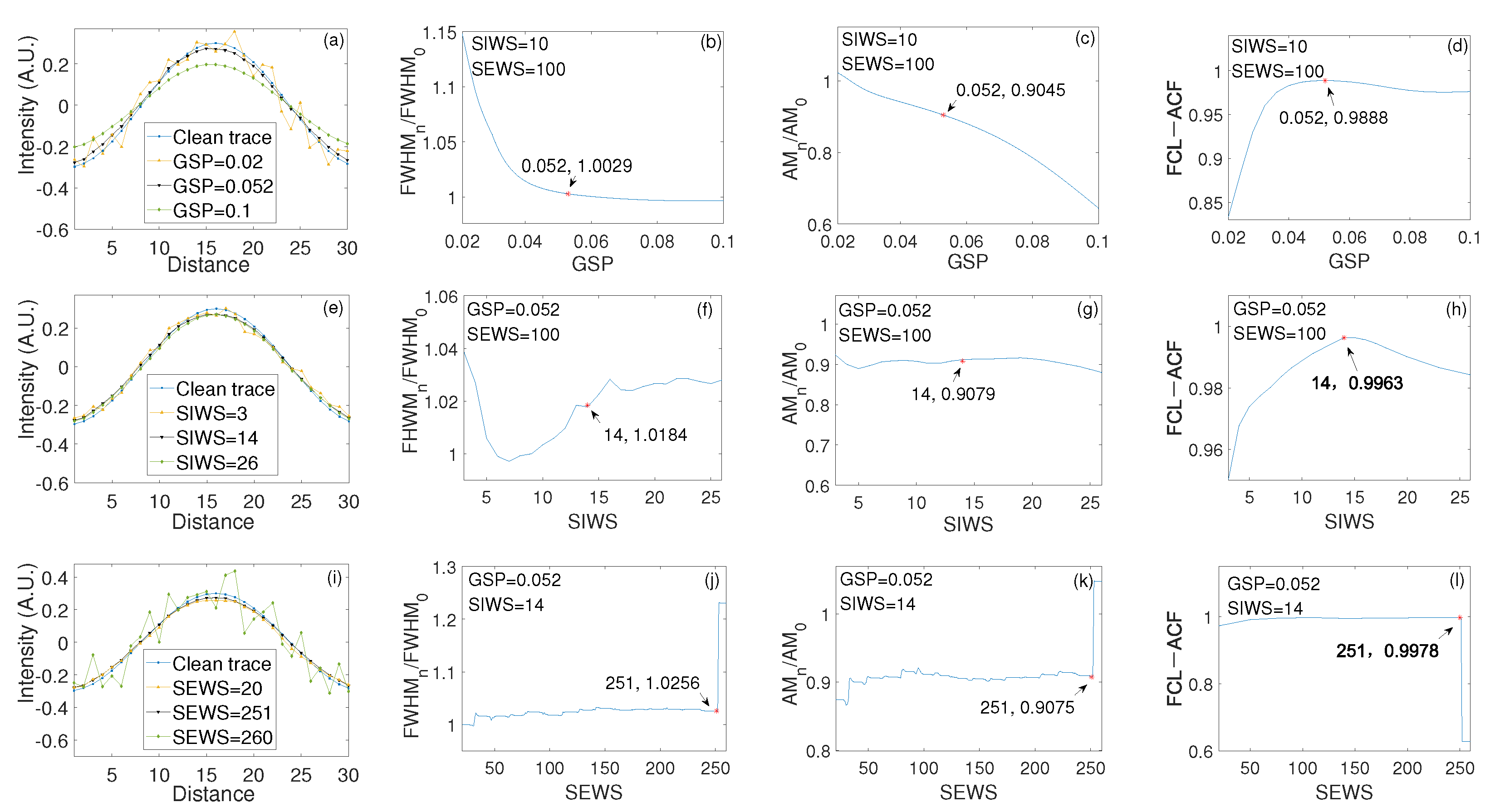
The traces denoised with three GSP values (0.02, 0.052, 0.1) are significantly different from the clean trace (blue line) when SIWS = 10 and SEWS = 100, as shown in Figure 4a. Obviously, the GSP = 0.02 has little denoising effect on the noisy trace. Figure 4b shows that the FWHM n /FWHM 0 decreases rapidly from 1.15 to 0.99 and then decreases slowly as GSP increases from 0.02 to 0.1. It decreases to 1.0029 (red asterisk), as shown in Figure 4b, when the optimal GSP results in the best denoising quality (FCL-ACF reaches its maximum 0.052 [17]), as shown in Figure 4d. Compared with the FWHM 0 , the FWHM n of the denoised trace is only 0.29% wider than the FWHM 0 of the clean one. Thus, if the GSP is optimal, the signal broadening of the denoising trace is less affected by the GSP.
The traces denoised with three SIWS values (3, 14, 26) are almost identical to the clean trace (blue line) when GSP = 0.052 and SEWS = 100, as shown in Figure 4e. Obviously, the SIWS = 3 has little denoising effect on the noisy trace. Figure 4f shows that the FWHM n /FWHM 0 changes sharply when the GSP and SEWS are 0.052 and 100, respectively, and the SIWS increases from 3 to 26. It expands to 1.0184 (red asterisk), as shown in Figure 4f, when the optimal SIWS results in the best denoising quality (FCL-ACF reaches its maximum 14 [17]), as shown in Figure 4h. Compared with the denoised result (FWHM n /FWHM 0 = 1.0029) in Figure 4b, the FWHM n /FWHM 0 is significantly increased by 1.55%. Therefore, even if the GSP and SIWS are optimal, the signal broadening of the denoising trace is still severely affected by the SIWS.
The traces denoised with three SEWS values (20, 251, 260) are almost identical to the clean trace (blue line) when GSP = 0.052 and SIWS = 14, as shown in Figure 4i. Obviously, the SEWS = 260 has no denoising effect on the noisy trace. Figure 4j shows that the FWHM n /FWHM 0 fluctuates slightly as the SEWS increases from 30 to 251, except for very small (<30) or very large (>251) SEWS when the GSP and SIWS are the optimal values of 0.052 and 14, respectively [17]. It increases to 1.0256 (red asterisk), as shown in Figure 4j, when the optimal SEWS results in the best denoising quality (FCL-ACF reaches its maximum 251 [17]), as shown in Figure 4l. Compared with the denoised result (FWHM n /FWHM 0 = 1.0184) of Figure 4f, the FWHM n /FWHM 0 increases by only 0.72%. Therefore, the signal broadening of the denoised trace is not significantly affected by the SEWS when the GSP, SIWS, and SEWS are optimal.

3.2. AM Varies with NLM Parameters

Figure 4c shows the AM n /AM 0 of the denoised trace decreases continuously from 1.02 to 0.65 when SIWS and SEWS are 10 and 100, respectively, and GSP increases from 0.02 to 0.1. It becomes 0.9045 (red asterisk), as shown in Figure 4c, when the optimal GSP results in the best denoising quality (FCL-ACF reaches its maximum), as shown in Figure 4d. The AM n of the denoised signal is 9.55% lower than AM 0 of the clean signal. Thus, the amplitude is heavily smoothed by the GSP even if the GSP is optimal.
Figure 4g shows that the AM n /AM 0 remains almost constant when the GSP and SEWS are 0.052 and 100, respectively, and the SIWS increases from 3 to 26. It becomes 0.9079 (red asterisks), as shown in Figure 4g when the optimal SIWS results in the best denoising quality (FCL-ACF reaches its maximum), as shown in Figure 4h. This value is only 0.35% lower than that in Figure 4c. Thus, the amplitude is almost unchanged by SIWS if the GSP and SIWS are optimal.
Figure 4i shows that when the GSP and SIWS are set to optimal values of 0.52 and 14, respectively, and the SEWS increases from 20 to 260, the AM n /AM 0 fluctuates only slightly, except for very small (<30) or very large (>251) SEWS value. It drops to 0.9075 (red asterisk), as shown in Figure 4i, when the optimal SEWS results in the best denoising quality (FCL-ACF reaches its maximum), as shown in Figure 4l. This value is only 0.04% lower than that in Figure 4g. Thus, the amplitude is very little affected by SEWS when the GSP, SIWS, and SEWS are optimal.

3.3. Analysis

As listed in Table 1, after optimizing the NLM parameters one by one, the FWHM n /FWHM 0 expands to 100.29%, 101.84%, and 102.56%, respectively, and the AM n /AM 0 becomes 90.45%, 90.79%, and 90.75%, respectively.
The FWHM n broadening caused by each NLM parameter is 0.29%, 1.55%, and 0.72%, respectively, which indicates that the FWHM broadening is mainly caused by the SIWS. The AM n change caused by each NLM parameter is 9.55%, 0.05%, and −0.04%, respectively, which indicates that the decrease in AM is mainly caused by the GSP. It is worth noting that if all the NLM parameters are optimal, the FWHM of the denoised trace only expands by only 2.56% compared with that of the clean trace, which is much less than the previous results [13,14,19,20,22]. The total signal amplitude is reduced by 9.25% compared with the clean trace.

4. SR of φ -OTDR Signals Varies with NLM Parameters

As shown in Figure 1a, the φ -OTDR signal is denoised by NLM. The signal trace with the largest intensity is analysed to obtain the relationship between the SR of φ -OTDR and the NLM parameters. It is better to use a clean reference signal to precisely evaluate the degree of SR degradation. In the absence of a clean signal, only the raw signal can be used to evaluate SR degradation.

4.1. FWHM Varies with NLM Parameters

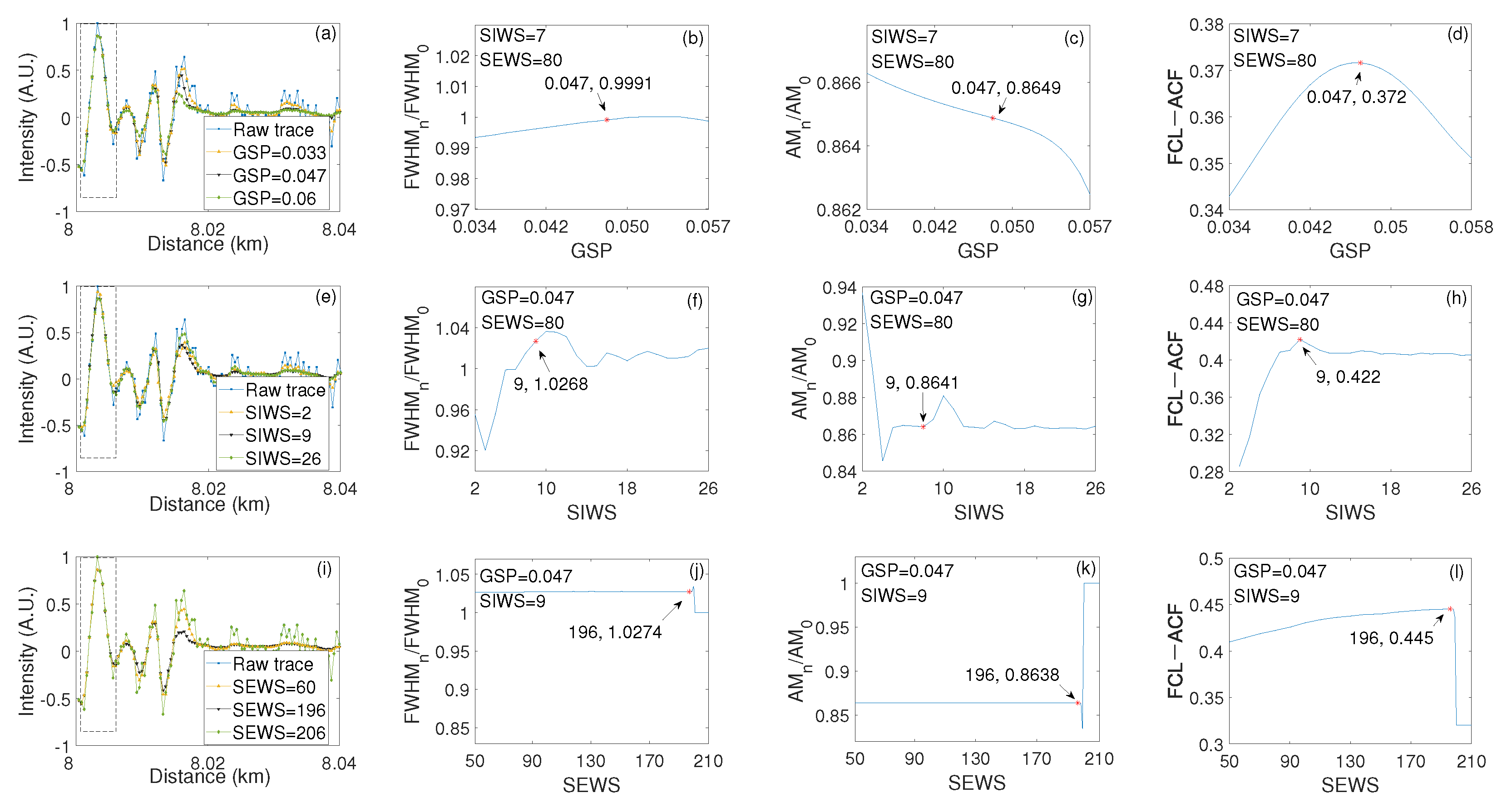
The traces with the highest intensity are denoised with three GSP values (0.033, 0.047, 0.06) respectively when the SIWS = 7 and SEWS = 80, respectively, as shown in Figure 5a. There is no noticeable difference between the traces in the first 40 m of sensing fiber, while there is a significant difference in the last 60 m. The FWHM n /FWHM 0 increases and then decreases as the GSP increases from 0.034 to 0.057, as shown in Figure 5b. It reaches the maximum of 0.9991 (red asterisk), as shown in Figure 5b, when the optimal GSP results in the best denoising quality (FCL-ACF reaches its maximum 0.047 [17]), as shown in Figure 5d. The FWHM n of the denoised trace is 0.09% lower than the FWHM 0 of the raw trace. Thus, the signal broadening of the denoised trace is almost unaffected by the GSP when the GSP is optimal.
The traces are denoised with three SIWS values (2, 9, 26), respectively, when GSP = 0.047 and SEWS = 80, as shown in Figure 5e. The FWHM n /FWHM 0 fluctuates slightly as the SIWS increases from 2 to 26, except for the small SIWS. It increases to 1.0268 (red asterisk), as shown in Figure 5f, when the optimal SIWS results in the best denoising quality (FCL-ACF reaches its maximum 9 [17]), as shown in Figure 5h. It is 2.77% larger than that of Figure 5b. Thus, the signal broadening of the denoised trace is severely affected by the SIWS even if the GSP and SIWS are optimal.
The traces are denoised with three SEWS values (60, 196, 206), respectively, when GSP = 0.047 and SIWS = 9, as shown in Figure 5i. The FWHM n /FWHM 0 is almost unchanged as SEWS increases from 50 to 210, as shown in Figure 5j. It reaches 1.0274 (red asterisk), as shown in Figure 5j, when the optimal SEWS results in the best denoising quality (FCL-ACF reaches its maximum 196 [17]), as shown in Figure 5l. The FWHM n /FWHM 0 of Figure 5j is 0.06% higher than that of Figure 5f. Thus, the signal broadening of the denoised trace is almost unaffected by the SEWS when the GSP, SIWS, and SEWS are optimal.

4.2. AM Varies with NLM Parameters

Figure 5c shows the AM n /AM 0 decreases monotonically from 0.8662 to 0.8623 when the SIWS and SEWS are 7 and 80, respectively, and the GSP increases from 0.034 to 0.057. It decreases to 0.8649 (red asterisk), as shown in Figure 5c, when the optimal GSP results in the best denoising quality (FCL-ACF reaches its maximum), as shown in Figure 5d. The AM n of the denoised trace is 13.51% less than the AM 0 of the raw trace. Thus, the amplitude of the denoised signal is severely reduced by the GSP even if the GSP is optimal.
Figure 5g shows that when the GSP and SEWS are 0.047 and 80, respectively, and the SIWS increases from 2 to 26, the AM n /AM 0 fluctuates slightly except for very small SIWS. It is 0.8641 (red asterisk), as shown in Figure 5g, when the optimal SIWS results in the best denoising quality (FCL-ACF reaches its maximum), as shown in Figure 5h. The AM n of the denoised trace decreases by 0.08% compared with the AM n /AM 0 (red asterisk) of Figure 5c. Thus, the amplitude of the denoised signal is basically unaffected by the SIWS when the GSP and SIWS are optimal.
Figure 5i shows that when the GSP and SIWS are 0.047 and 9, respectively, and the SEWS increases from 50 to 210, the AM n /AM 0 remains almost constant, except for very large SEWS. It becomes 0.8638 (red asterisk), as shown in Figure 5i, when the optimal SEWS results in the best denoising quality (FCL-ACF reaches its maximum), as shown in Figure 5l. The AM n of the denoised trace decreases by 0.03% compared with the AM n /AM 0 (red asterisk) of Figure 5g. Thus, the amplitude of the denoised signal is almost unaffected by SEWS when the GSP, SIWS, and SEWS are optimal.

4.3. Analysis

By optimizing the NLM parameters, as listed in Table 2, the FWHM n /FWHM 0 becomes 99.91%, 102.68%, and 102.74%, respectively, and the AM n /AM 0 decreases to 86.49%, 86.41%, and 86.38%, respectively. The FWHM n broadening caused by each NLM parameter is −0.09%, 2.77%, and 0.06%, which indicates that the FWHM broadening is mainly caused by the SIWS. The AM n change caused by each NLM parameter is 13.51%, 0.08%, and 0.03%, respectively, which indicates that the decrease in AM is mainly due to the GSP. When all the NLM parameters are optimal, the denoised trace is only broadened by 2.74% compared with the raw trace, which is much less than the previous results [13,14,19,20,22]. The total signal amplitude is reduced by 13.62% compared with the raw trace.

5. Discussion

As reported in previous studies, the deterioration of SR due to NLM is compared with the corresponding data as listed in Table 3. The ratio of SR deterioration caused by NLM is calculated using the following equation:
SR Degradation percentage = NLM SR Corresponding SR Corresponding SR × 100 % ,
where NLM SR represents the SR of the signal denoised by NLM, the corresponding SR states the SR of the signal obtained from the AAD [14], the ideal data [19], the Gaussian filtered results [20], and the data averaged over 5000 measurements [22], respectively. Compared to the corresponding SR of the AAD, Gaussian filtering, and the average of 5000 measurements, the SR degradation percentages caused by NLM are 93%, 275%, 84%, and 8.97%, respectively. These results are much worse than our findings, where the SR degradation percentages for the mimic signal and the measured φ -OTDR signal were 2.56% and 2.74%, respectively. The main reason for SR deterioration is the use of inappropriate NLM parameters, especially the small SIWS. Therefore, it is essential to optimize the filtering parameters of image processing methods before evaluating the SR degradation. Recently, FCL-ACF has been proven to be suitable for optimizing NLM parameters [17]. However, it is only suitable for periodic signals. As a result, the SR degradation evaluation method proposed in this menuscript is applicable to perodic signals. Although it cannot be used to evaluate non-periodic signals, the degree of SR degradation caused by NLM can provide reference for other DFOS such as B-OTDR and R-OTDR. It is worth mentioning that although the SR degradation of the mimic signal and the measured φ -OTDR signal were evaluated using clean and noisy signals, respectively, the difference in SR degradation (2.56% and 2.74%) is very small. To improve the MA without significantly reducing SR, the SIWS should be comparable to the smallest details in the signal. In this case, the appropriate SIWS is the period of the signal.

6. Conclusions

The cause and the extent of the SR of DFOS affected by NLM parameters were explored through quantitative analysis of the relationship between the FWHM of the signal trace and the NLM parameter based on the mimic and measured φ -OTDR signals. The analysis results show that the deterioration of the SR caused by the NLM parameters is ranked from high to low as follows:
For the denoised mimic signal,
  • 1.55% (SIWS) > 0.72% (SEWS) > 0.29% (GSP);
For the denoised φ -OTDR signal,
  • 2.77% (SIWS) > 0.06% (SEWS) > 0.09% (GSP).
The degradation of the signal AM caused by the NLM parameter is ranked from high to low as follows:
For the denoised mimic signal,
  • 9.55% (GSP) > 0.05% (SIWS) > 0.04% (SEWS);
For the denoised φ -OTDR signal,
  • 13.51% (GSP) > 0.08% (SIWS) > 0.03% (SEWS).
Therefore, the main reason for the deterioration of the SR is the SIWS, while the main reason for the degradation of signal AM is the GSP. The total FWHM broadening of the mimic and measured φ -OTDR signals after denoising are 2.56% and 2.74%, respectively, which is much less than the previous results [13,14,19,20,22]. Therefore, the SR of DFOS only slightly deteriorates when the best SNR of DFOS is obtained using NLM with optimal parameters. This work contributes to the simultaneous improvement of SR and MA of DFOS by using NLM.

Author Contributions

Y.C. and S.Z. are co-first authors and contributed equally to this work; Conceptualization, Y.C. and S.Z.; methodology, P.Z. and W.C.; software, Y.C. and S.Z.; validation, K.Y. and M.W.; formal analysis, Y.C. and S.Z.; investigation, K.Y.; data curation, L.F.; writing—original draft preparation, Y.C. and S.Z.; writing—review and editing, P.Z.; visualization, Y.C. and S.Z.; supervision, W.C.; funding acquisition, W.C. and P.Z. All authors have read and agreed to the published version of the manuscript.

Funding

This work was supported in part by the Educational and Scientific Research Projects for Young and Middle-aged Teachers of Fujian under Grant [JAT200236, JAT200289] and the Natural Science Foundation of Fujian Science and Technology Plan under Grant [2022J01824, 2021J01866].

Institutional Review Board Statement

Not applicable.

Informed Consent Statement

Not applicable.

Data Availability Statement

Data available on request from the authors.

Conflicts of Interest

The authors declare no conflict of interest.

References

  1. Soto, M.A.; Ramírez, J.A.; Thévenaz, L. Intensifying the response of distributed optical fibre sensors using 2D and 3D image restoration. Nat. Commun. 2016, 7, 10870. [Google Scholar] [CrossRef]
  2. Soto, M.A.; Ramírez, J.A.; Thévenaz, L. Reaching millikelvin resolution in Raman distributed temperature sensing using image processing. In Proceedings of the Sixth European Workshop on Optical Fibre Sensors (EWOFS’2016), Limerick, Ireland, 31 May–3 June 2016; Volume 9916. [Google Scholar]
  3. Wang, X.; Wang, Z.; Wang, S.; Xue, N.; Sun, W.; Zhang, L.; Zhang, B.; Rao, Y. 157 km BOTDA with pulse coding and image processing. In Proceedings of the Sixth European Workshop on Optical Fibre Sensors (EWOFS’2016), Limerick, Ireland, 31 May–3 June 2016; Volume 9916. [Google Scholar]
  4. Guo, N.; Wang, L.; Wu, H.; Jin, C.; Tam, H.-Y.; Lu, C. Enhanced coherent BOTDA system without trace averaging. J. Light. Technol. 2018, 36, 871–878. [Google Scholar] [CrossRef]
  5. Zhao, S.; Cui, J.; Wu, Z.; Tan, J. Accuracy improvement in OFDR-based distributed sensing system by image processing. Opt. Laser Eng. 2020, 124, 105824. [Google Scholar] [CrossRef]
  6. Soto, M.A.; Ramírez, J.A.; Thévenaz, L. Optimizing Image Denoising for Long-Range Brillouin Distributed Fiber Sensing. J. Light. Technol. 2018, 36, 1168–1177. [Google Scholar] [CrossRef]
  7. Qian, X.; Wang, Z.; Sun, W.; Zhang, B.; He, Q.; Zhang, L.; Wu, H.; Rao, Y. Long-range BOTDA denoising with multi-threshold 2D discrete wavelet. In Proceedings of the Asia-Pacific Optical Sensors Conference (APOS), OSA Technial Digest, Shanghai, China, 11–14 October 2016; p. W4A.24. [Google Scholar]
  8. He, H.; Shao, L.; Li, H.; Pan, W.; Luo, B.; Zou, X.; Yan, X. SNR enhancement in phase-sensitive OTDR with adaptive 2-D bilateral filtering algorithm. IEEE Photonics J. 2017, 9, 6802610. [Google Scholar] [CrossRef]
  9. Wu, H.; Wang, L.; Zhao, Z.; Guo, N.; Shu, C.; Lu, C. Brillouin optical time domain analyzer sensors assisted by advanced image denoising techniques. Opt. Express 2018, 26, 5126–5139. [Google Scholar] [CrossRef]
  10. Wang, B.; Wang, L.; Yu, C.; Lu, C. Long-distance BOTDA sensing systems using video-BM3D denoising for both static and slowly varying environment. Opt. Express 2019, 27, 36100–36113. [Google Scholar] [CrossRef] [PubMed]
  11. Huang, Z.; Li, D.; Feng, Y.; Jiang, X.; Wang, L. Application of adaptive NLM denoising algorithm in BOTDA. In Proceedings of the Global Intelligent Industry Conference, Guangzhou, China, 16–17 December 2021; Volume 11780, p. 117801B. [Google Scholar]
  12. Li, J.; Zeng, K.; Yang, G.; Wang, L.; Mi, J.; Wan, L.; Tang, M.; Liu, D. High-fidelity denoising for differential pulse-width pair brillouin optical time domain analyzer based on block-matching and 3D filtering. Opt. Commun. 2022, 525, 128866. [Google Scholar] [CrossRef]
  13. Luo, K.; Wang, B.; Guo, N.; Kuanglu, Y.U.; Lu, C. Enhancing SNR by anisotropic diffusion for brillouin distributed optical fiber sensors. J. Light. Technol. 2020, 38, 5844–5852. [Google Scholar] [CrossRef]
  14. Zhang, P.; Wang, B.; Yang, Y.; Azad, A.K.; Luo, K.; Yu, K.; Yu, C.; Lu, C. SNR enhancement for Brillouin distributed optical fiber sensors based on asynchronous control. Opt. Express 2022, 30, 4231–4248. [Google Scholar] [CrossRef] [PubMed]
  15. Qian, X.; Jia, X.; Wang, Z.; Zhang, B.; Xue, N.; Sun, W.; He, Q.; Wu, H. Noise level estimation of BOTDA for optimal non-local means denoising. Appl. Opt. 2017, 56, 4727–4734. [Google Scholar] [CrossRef]
  16. Xu, S.; Jiang, S.; Min, W. No-reference/blind image quality assessment: A survey. IETE Tech. Rev. 2017, 34, 223–245. [Google Scholar] [CrossRef]
  17. Wu, M.; Chen, Y.; Zhu, P.; Chen, W. NLM parameter optimization for φ-OTDR signal. J. Light. Technol. 2022, 40, 6045–6051. [Google Scholar] [CrossRef]
  18. Chen, Y.; Zhu, P.; Yin, Y.; Wu, M.; Yu, K.; Feng, L.; Chen, W. Objective assessment of IPM denoising quality of φ-OTDR signal. Measurement 2023, 214, 112775. [Google Scholar] [CrossRef]
  19. Zhang, Y.; Lu, Y.; Zhang, Z.; Wang, J.; He, C.; Wu, T. Noise reduction by brillouin spectrum reassembly in brillouin optical time domain sensors. Opt. Laser Eng. 2020, 125, 105865. [Google Scholar] [CrossRef]
  20. Zhang, Y.; Lu, Y.; Chen, L.; Wu, T.; He, C. Segmented noise reduction based on Brillouin-spectrum-partition in Brillouin optical time domain sensors. IEEE Sens. J. 2021, 21, 22792–22802. [Google Scholar] [CrossRef]
  21. Shen, L.; Zhao, Z.; Zhao, C.; Wu, H.; Lu, C.; Tang, M. Improving the spatial resolution of a BOTDA sensor using deconvolution algorithm. J. Light. Technol. 2021, 39, 2215–2222. [Google Scholar] [CrossRef]
  22. Yuan, P.; Lu, Y.; Zhang, Y.; Zhang, Z. Noise reduction in a Brillouin optical time-domain sensor by a frequency-domain feature filter. Appl. Opt. 2022, 61, 2667–2674. [Google Scholar]
  23. Zhang, Z.; Wu, H.; Zhao, C.; Tang, M. High-performance raman distributed temperature sensing powered by deep learning. J. Light. Technol. 2021, 39, 654–659. [Google Scholar] [CrossRef]
  24. Ge, Z.; Shen, L.; Zhao, C.; Wu, H.; Zhao, Z.; Tang, M. Enabling variable high spatial resolution retrieval from a long pulse BOTDA sensor. IEEE Internet Things 2022, 10, 1813–1821. [Google Scholar] [CrossRef]
  25. Datta, A.; Raj, V.; Sankar, V.; Kalyani, S.; Srinivasan, B. Measurement accuracy enhancement with multi-event detection using the deep learning approach in Raman distributed temperature sensors. Opt. Express 2021, 29, 26745–26764. [Google Scholar] [CrossRef] [PubMed]
  26. Hu, D.J.J.; Humbert, G.; Dong, H.; Zhang, H.; Hao, J.; Sun, Q. Review of Specialty Fiber Based Brillouin Optical Time Domain Analysis Technology. Photonics 2021, 8, 421. [Google Scholar] [CrossRef]
  27. Sun, Y.; Li, H.; Fan, C.; Yan, B.; Chen, J.; Yan, Z.; Sun, Q. Review of a Specialty Fiber for Distributed Acoustic Sensing Technology. Photonics 2022, 9, 277. [Google Scholar] [CrossRef]
  28. Zhang, H.; Dong, H.; Hu, D.J.J.; Hao, J. Overcoming the Lead Fiber-Induced Limitation on Pulse Repetition Rate in Distributed Fiber Sensors. Photonics 2022, 9, 965. [Google Scholar] [CrossRef]
  29. Liu, X.; Wu, H.; Wang, Y.; Tu, Y.; Sun, Y.; Liu, L.; Song, Y.; Wu, Y.; Yan, G. A Fast Accurate Attention-Enhanced ResNet Model for Fiber-Optic Distributed Acoustic Sensor (DAS) Signal Recognition in Complicated Urban Environments. Photonics 2022, 9, 677. [Google Scholar] [CrossRef]
  30. Buades, A.; Coll, B.; Morel, J. A non-local algorithm for image denoising. In Proceedings of the 2005 IEEE Computer Society Conference on Computer Vision and Pattern Recognition (CVPR’05), San Diego, CA, USA, 20–25 June 2015; pp. 60–65. [Google Scholar]
Figure 1. (a) Vibration signal of φ -OTDR, (b) FWHM represent the SR of φ -OTDR.
Photonics 10 00529 g001
Figure 2. Analysis steps of the relationship between the SR of DFOS and the NLM parameters.
Photonics 10 00529 g002
Figure 3. (a) A clean image and (b) Corrupted by noise.
Photonics 10 00529 g003
Figure 4. The FWHM, AM, and FCL-ACF vary with each NLM parameter (GSP, SIWS, and SEWS) based on the simulated signal: (a) Trace profile vs. GSP; (b) FWHM vs. GSP; (c) AM vs. GSP; (d) FCL-ACF vs. GSP; (e) Trace profile vs. SIWS; (f) FWHM vs. SIWS; (g) AM vs. SIWS; (h) FCL-ACF vs. SIWS; (i) Trace profile vs. SEWS; (j) FWHM vs. SEWS.; (k) AM vs. SEWS; (l) FCL-ACF vs. SEWS.
Photonics 10 00529 g004
Figure 5. The FWHM, AM, and FCL-ACF vary with each NLM parameter (GSP, SIWS, and SEWS) based on the φ -OTDR signal: (a) Trace profile vs. GSP; (b) FWHM vs. GSP; (c) AM vs. GSP; (d) FCL-ACF vs. GSP; (e) Trace profile vs. SIWS; (f) FWHM vs. SIWS; (g) AM vs. SIWS; (h) FCL-ACF vs. SIWS; (i) Trace profile vs. SEWS; (j) FWHM vs. SEWS; (k) AM vs. SEWS; (l) FCL-ACF vs. SEWS.
Photonics 10 00529 g005
Table 1. FWHM, AM, and FCL-ACF of the denoised signal affected by each NLM parameter based on a mimic signal.
ParameterFWHM n /FWHM 0 AM n /AM 0 FCL-ACF
GSP100.29%90.45%0.9888
SIWS101.84%90.79%0.9963
SEWS102.56%90.75%0.9978
Table 2. FWHM, AM, and FCL-ACF of the denoised signal affected by each NLM parameter based on a φ -OTDR signal.
ParameterFWHM n /FWHM 0 AM n /AM 0 FCL-ACF
GSP99.91%86.49%0.372
SIWS102.68%86.41%0.422
SEWS102.74%86.38%0.445
Table 3. The degradation of NLM SR compared to the corresponding SR.
SR DegradationADD [14]Ideal Data [19]Gaussian Filter [20]5000 Average [22]
Percentage93%275%84%8.97%
Disclaimer/Publisher’s Note: The statements, opinions and data contained in all publications are solely those of the individual author(s) and contributor(s) and not of MDPI and/or the editor(s). MDPI and/or the editor(s) disclaim responsibility for any injury to people or property resulting from any ideas, methods, instructions or products referred to in the content.