Communication

Highly Birefringent and Low-Loss Hollow-Core Anti-Resonant Fiber Based on a Hybrid Guidance Mechanism

1
School of Information Engineering, Huangshan University, Huangshan 245041, China
2
Hangzhou Institute of Advanced Studies, Zhejiang Normal University, Hangzhou 311231, China
3
Key Laboratory of Optical Information Detection and Display Technology of Zhejiang, Zhejiang Normal University, Jinhua 321004, China
4
College of Teacher Education, Quzhou University, Quzhou 324000, China
5
Ningbo Innovation Center, Zhejiang University, Ningbo 315100, China
*
Author to whom correspondence should be addressed.
Photonics 2023, 10(5), 525; https://doi.org/10.3390/photonics10050525
Submission received: 21 March 2023 / Revised: 26 April 2023 / Accepted: 30 April 2023 / Published: 4 May 2023
(This article belongs to the Special Issue Fiber Lasers and Fiber Sensors)

Abstract

:
A highly birefringent and low-loss hollow-core anti-resonant fiber (HC-ARF) based on a hybrid guidance mechanism is proposed and investigated by using a finite element method. The hybrid guidance mechanism is caused by the anti-resonance effect and the total internal reflection effect. The proposed HC-ARF is obtained by employing twin symmetrical and mutually tangential elliptical arc anti-resonance layers (EA-ARLs) in a conventional 8-tube HC-ARF. Because of the anti-resonance mechanism and the total internal reflection mechanism in the EA-ARL, mode coupling appears between the core mode and the cladding mode. Simulation results indicate that the proposed HC-ARF can achieve birefringence as high as 10−2 in a near-infrared range of 1400 nm to 1600 nm and a low confinement loss (CL) of 7.74 × 10⁻⁴ dB/m (9.26 × 10⁻⁴ dB/m) for x- and y-polarization components of the fundamental mode (FM) at 1550 nm. In addition, the existence of the 8-tube anti-resonance structure in the cladding significantly suppresses the CL of the x-polarization component of the FM significantly, but the impact on the CL of the y-polarization FM can be ignored, which is determined mainly by the twin EA-ARLs. Furthermore, the performance of the birefringence and CL are also investigated by changing the values of other fiber structure parameters. Our proposed structure successfully shows the ability of the hybrid guidance mechanism in the application of CL manipulation of orthogonal polarization components.

1. Introduction

Highly birefringent fibers are widely used in optical communication systems, optical sensors, optical filters, and interference devices [1]. In the past decades, researchers have developed photonic crystal fibers (PCFs) with ultra-high birefringence based on total internal reflection light-guiding mechanisms. For example, ultra-high birefringence up to 10−2 at a wavelength of 1550 nm was obtained by constructing an asymmetric fiber core in a tiny region in the center of the PCF [2,3,4,5,6,7]. However, these solid-core highly birefringent PCFs have a some limitations, such as low damage threshold and significant absorption [8,9].
On the other hand, hollow-core fibers can confine optical light in its central air region in which the absorption losses are much lower than those in the dielectric media. The hollow-core fibers can also minimize the effect of the matrix material on light-guiding properties and significantly reduce fiber dispersion and optical nonlinearity, Therefore, the hollow-core fibers are considered as a promising alternative to PCFs [10,11].
The hollow-core fiber can be classified into two categories according to their light-guiding mechanism: the hollow-core photonic bandgap fiber (HC-PBGF) and the hollow-core anti-resonant fiber (HC-ARF). Photonic band gaps can be generated by using periodic air hole arrays in the cladding, and HC-PBGF is based on photonic bandgap effect for confining light in the fiber core [12,13] in which the birefringence can be caused by using asymmetric cores [14,15,16,17]. Although HC-PBGF can achieve high birefringence and low loss, it still has the disadvantages of limited transmission bandwidth, low damage threshold, severe group velocity dispersion, and poor spatial mode purity [18]. The best-reported results, which show a phase birefringence of 2.5 × 10⁻⁴ and a minimum loss of 4.9 dB/km, were achieved with a 19-cell PBGF designed by Fin et al. in 2014. However, its bandwidth was narrow, only 14 nm [17,19].
For HC-ARF, the light is guided by suppressing the coupling of core and cladding modes. Therefore, it has some optical characteristics, such as wide transmission bandwidth, extremely low loss, weaker group velocity dispersion, simple structure, and flexibility [20]. Furthermore, both light and matter are in the hollow core, resulting in a long interaction distance between light and matter, a compact structure, and a strong interaction between matter and fiber-guided light. Therefore, it can be used as a platform for lab-in-fiber and has important applications in mid-infrared laser [21] and mid-infrared gas detection [22]. In addition, it has potential application advantages in biomolecule detection based on the localized surface plasmon resonance (LSPR) effect. At present, fiber optic sensors based on LSPR usually use fiber splicing or form a tapered fiber structure to increase the interaction between the sensing biomolecules and the light wave to improve sensitivity when detecting some biological molecules, such as creatinine [23,24], cardiac troponin I [25,26], alanine aminotransferase [27], acetylcholine [28], aflatoxin B1 [29], and p-cresol [30,31]. By coating metal nanoparticles on the cladding tubes and using a syringe pump to fill the biomolecular analyte into the hollow core, the HC-ARF can be made into biosensors based on LSPR, which are expected to have potential advantages in biomolecule detection.
In recent years, researchers have made some progress in using anti-resonant fibers to design high-birefringence hollow-core fibers [32,33,34,35,36,37,38,39,40,41]. Currently, HC-ARFs are used mainly to achieve high birefringence by introducing asymmetry in its cladding tube, such as adjusting the thickness of the cladding tube in a certain polarization direction [1,9], using two nested tubes in a certain polarization direction [13], and nesting silicon layers in a certain polarization direction [32]. However, it is difficult for these fiber structures to obtain high birefringence, and the enhanced birefringence is still lower than 10−3. HC-ARF based on a hybrid guidance mechanism is considered as a solution to break through the birefringence limit. This type of fiber satisfies multiple light-guiding effects simultaneously, and we can design a highly birefringent fiber by using the advantage of different light-guiding mechanisms. Du et al. proposed a highly birefringent terahertz fiber with a birefringence higher than 10−2 and low loss of 1.69 × 10⁻⁴ dB/cm (9.14 × 10⁻³ dB/cm) for the x(y)-polarization component of the fundamental mode (FM) at 1 THz, which is based on the hybrid guidance mechanism of the anti-resonant mechanism and the total internal reflection mechanism [42]. Guo et al. studied a highly birefringent HC-ARF based on a hybrid guidance mechanism of the photonic bandgap mechanism and the anti-resonant mechanism, and a birefringence of 3.91 × 10⁻³ was achieved, while the loss was higher than 10−3 dB/km [10]. Research on hybrid waveguide-based hollow fiber is still relatively scarce, and only few superior properties have been found, which need to be further investigated.
In this study, a high birefringence and low-loss HC-ARF is proposed and investigated by using the finite-element method (FEM). The cladding of the HC-ARF is formed by a traditional pure 8-tube anti-resonance structure, and a pair of negative curvature and tangent elliptical arc anti-resonance layers (EA-ARLs) are employed in the hollow region. The twin EA-ARLs in our design introduce prominent structural asymmetry, which enhances the birefringence and decreases the confinement loss (CL) of the y-polarization component of the FM. Moreover, the 8-tube anti-resonant structure can significantly reduce the CL of the x-polarized FM, while the change of CL of the y-polarization component of the FM is negligible. Finally, the fiber properties are investigated by optimizing the structural parameters.

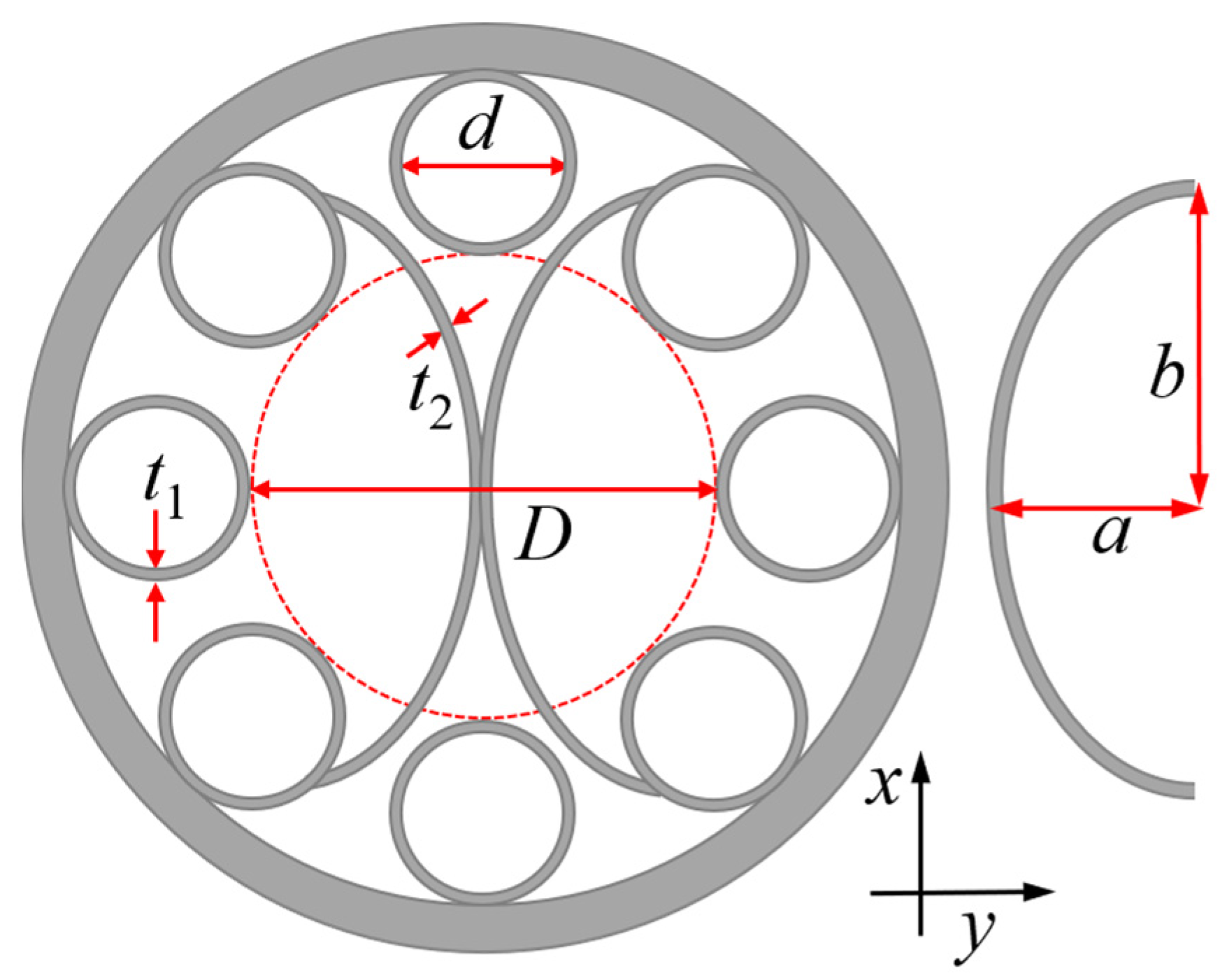
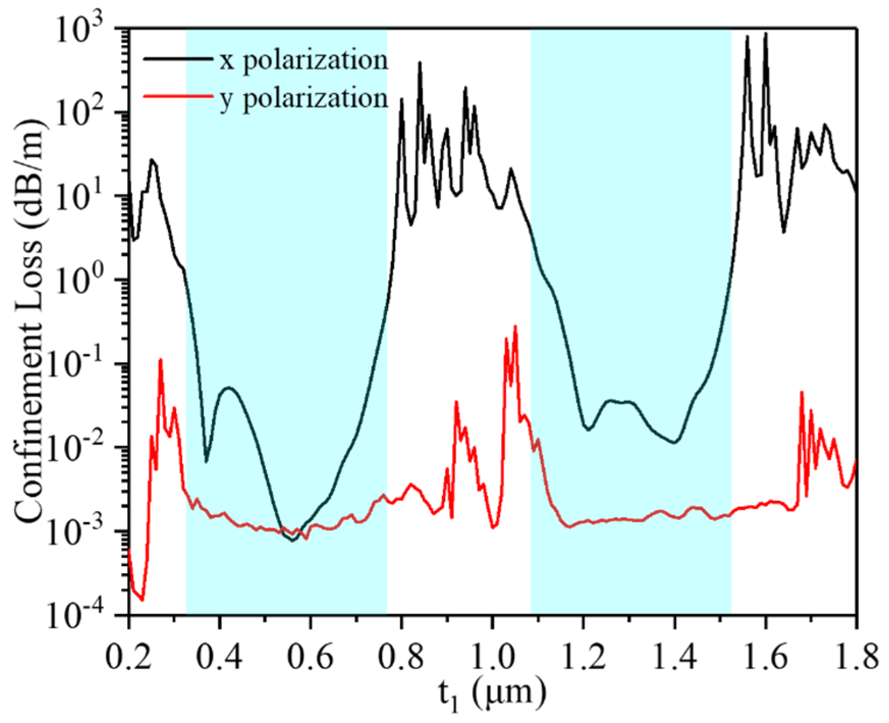
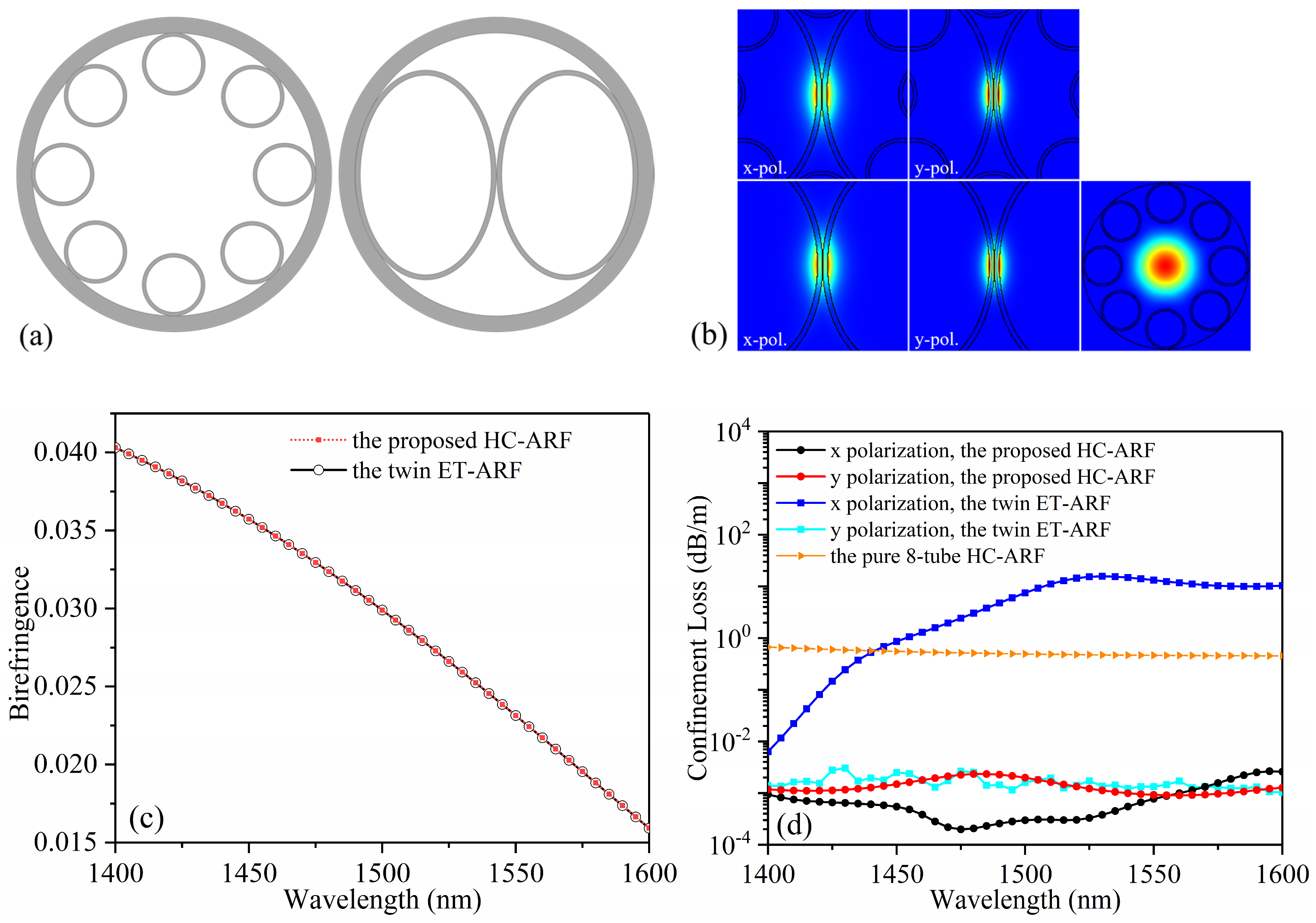
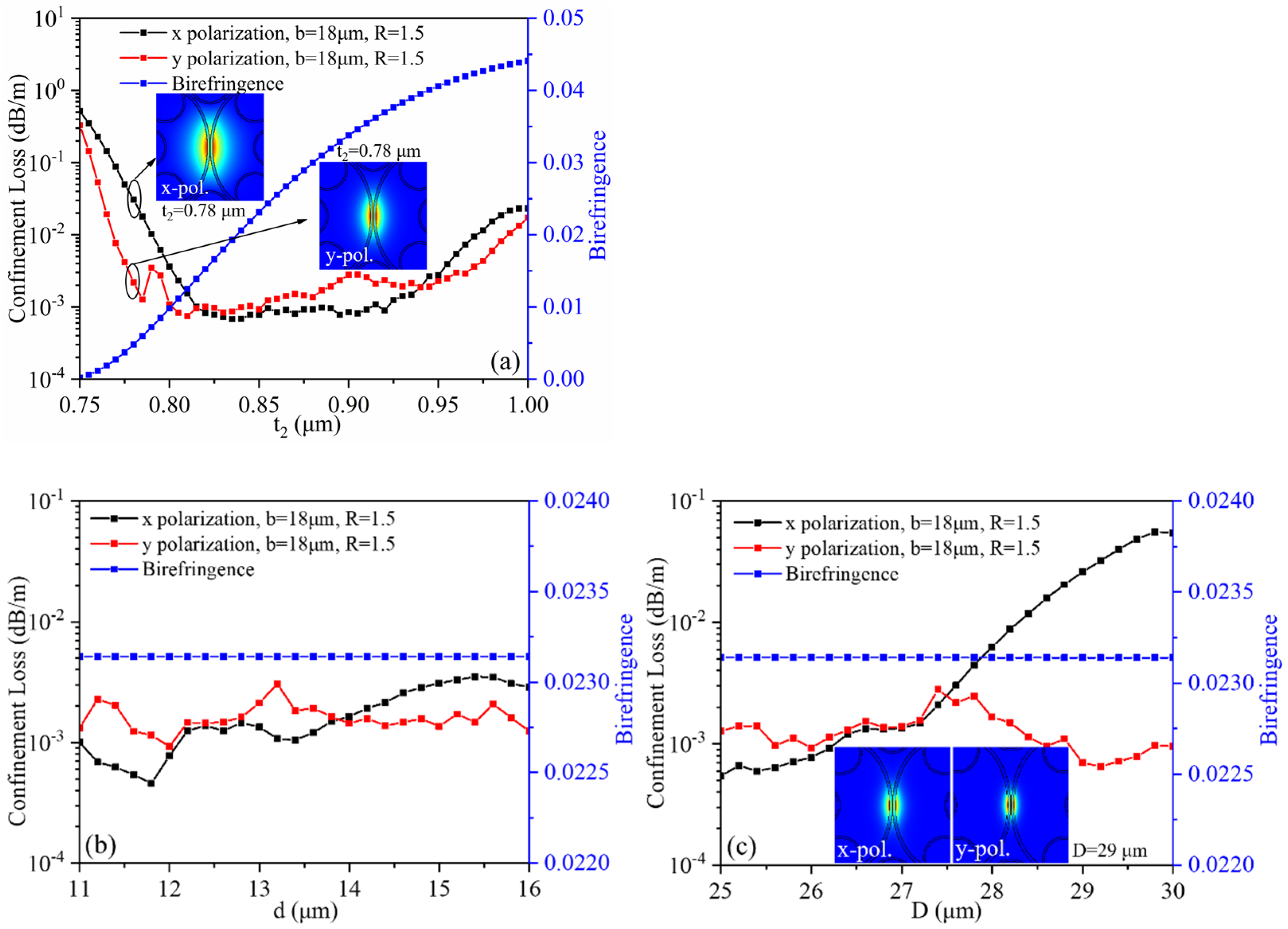
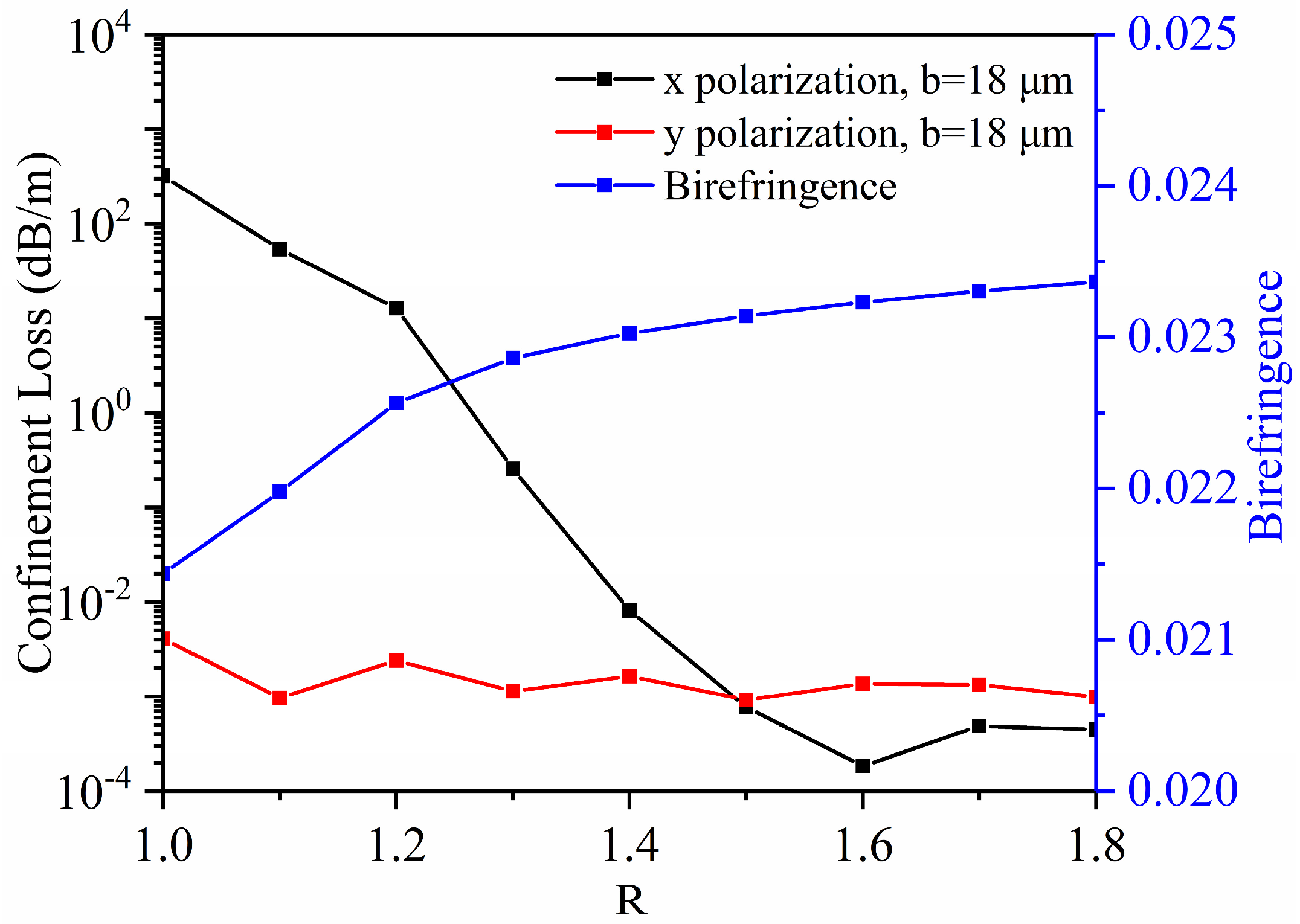
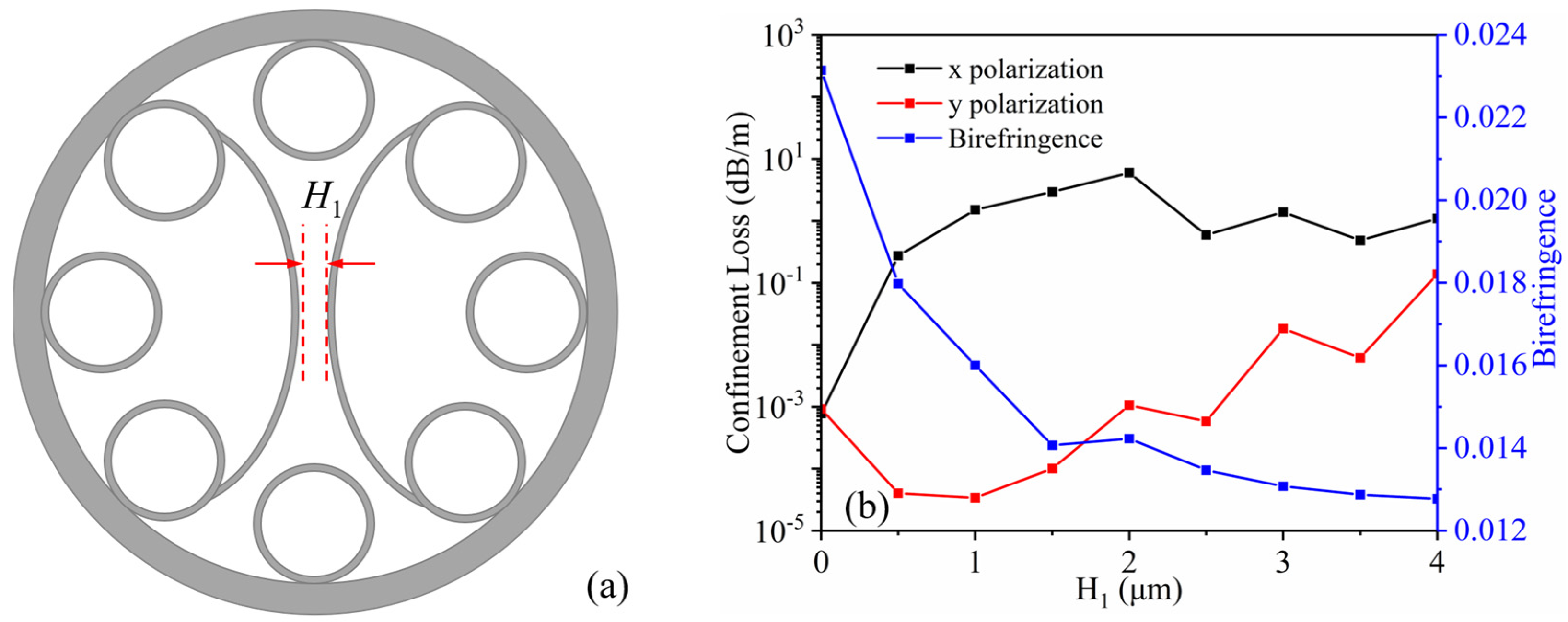
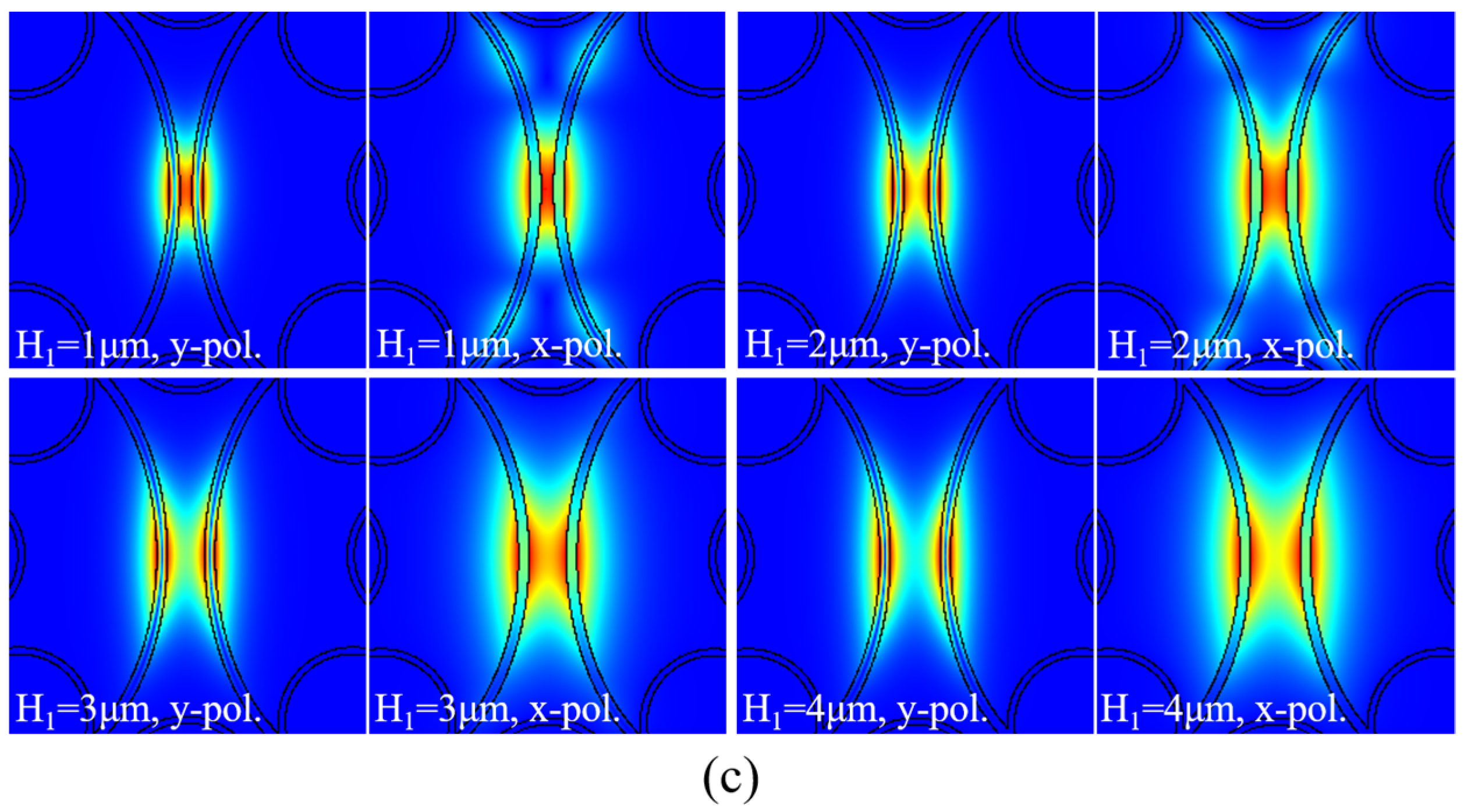
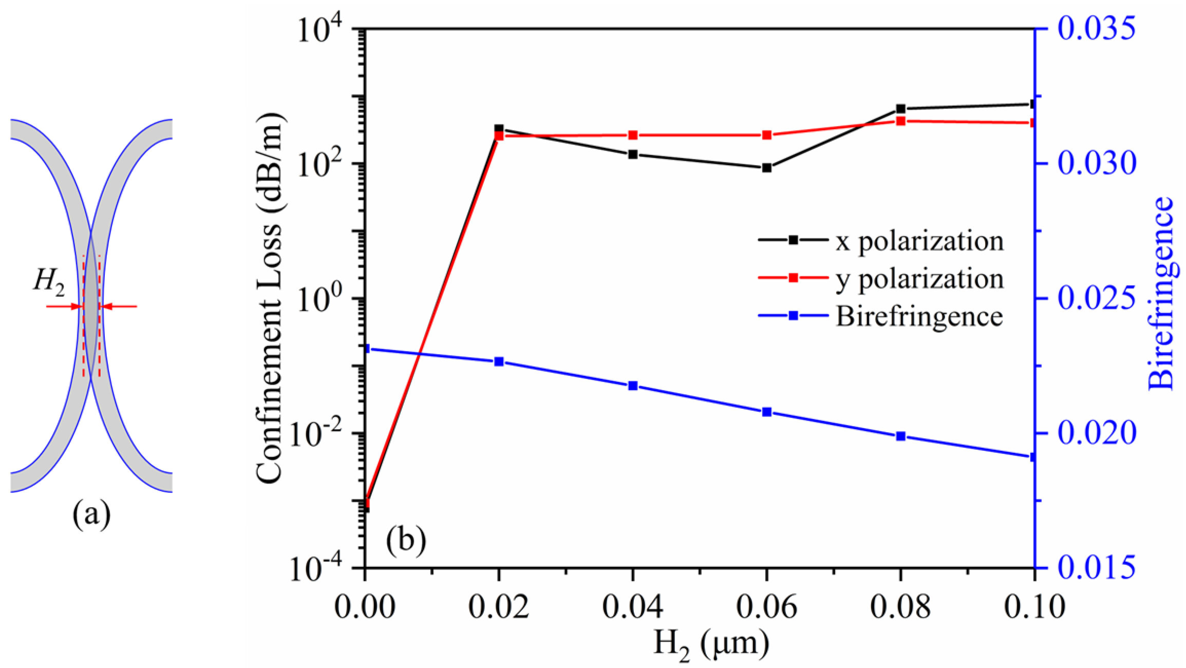
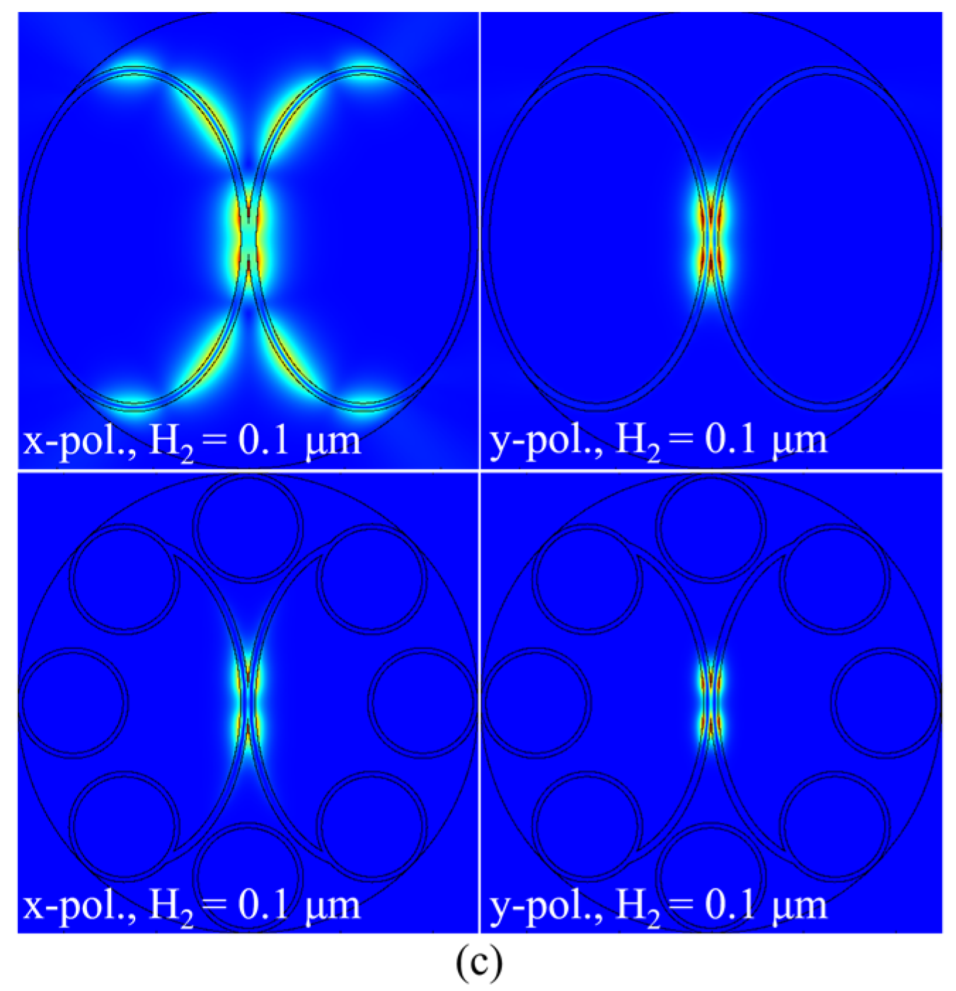
2. Fiber Structure and Performance Analysis

Figure 1 shows a cross-sectional schematic of the proposed HC-ARF which is composed of a pair of tangential negative curvature EA-ARLs in a typical pure 8-tube anti-resonant hollow structure. A waveguide structure is formed as a result of the interaction between the twin EA-ARLs. Thus, the proposed HC-ARF has a hybrid guidance mechanism that is combined with the anti-resonance effect and the total reflection effect, and it has features of high birefringence and low loss. As shown in Figure 1, d is the diameter of the cladding tube, t1 is its thickness, and D is the diameter of the hollow circular. t2 is the thickness of the EA-ARL, and the short and long semi-axes are denoted by a and b, respectively. The ellipticity of the EA-ARL is denoted by R, and R = b/a. In order to analyze the birefringence and CL performance of the proposed HC-ARF, its mode and transmission constants are calculated by using the finite element analysis method. The HC-ARF structure parameters in Figure 1 are D = 26 μm, d = 12 μm, t1 = 0.56 μm, t2 = 0.85 μm, b = 18 μm, and R = 1.5. To save computational resources, an anisotropic perfectly matched layer with a thickness of 15 μm is placed on the outside of the cladding. The maximum element size of the glass region is λ/10, and that of the air region is λ/8. Thus, the total mesh elements of the model reach 446,840, and the rate of the effective refractive index change in more dense mesh set is negligible at 0%.
The birefringence caused by the effective refractive index difference between the x- and y-polarization components of the FMs can be expressed as:
B = | n y n x |
where nx and ny are the effective refractive indices of the x and y polarization components of FMs, respectively. The CL of the fiber transmission mode can be calculated by the following formula [43,44]:
C L = 20 ln 10 ( 2 π λ ) Im ( n e f f )
where Im(neff) is the imaginary portion of the effective refractive index of the fiber polarization mode, and λ is the operating wavelength.
The dependence of the birefringence and confinement loss on the tube thickness t1 (0.2 μm to 1.8 μm) is analyzed. In our simulation, D = 26 μm, d = 12 μm, t2 = 0.85 μm, b = 18 μm, and R = 1.5. Our operating wavelength is set at 1550 nm, unless otherwise stated. As shown in Figure 2, it can be seen that there are two low-loss windows according to the loss variation. This means the light is strictly confined to the hollow core in the anti-resonant region. On the contrary, the core mode has a good phase match with the cladding mode in the resonant region, which results in high CL value. In the first low-loss window region, the lowest CL value (7.74 × 10⁻⁴ dB/m) was reached when the parameter t1 is 0.56 μm. Therefore, the tube thickness t1 is set as 0.56 μm for the following calculation.
To illustrate the function of the cladding 8-tube anti-resonant structure and the twin EA-ARLs, the birefringence characteristics between the proposed HC-ARF and the twin elliptical tube hollow-core anti-resonant fiber (ET-ARF) are analyzed. Furthermore, the differences of the CL characteristics among the twin ET-ARF, the pure 8-tube ARF, and the proposed HC-ARF are studied. Figure 3a shows two schematic diagrams of the cross-section of the twin ET-ARF and the pure 8-tube ARF. For comparison purposes, the dimensions and layer thicknesses of the elliptical ARL in both fibers are set as follows: t2 = 0.85 μm, b = 18 μm, and R = 1.5. For the geometric parameters of the cladding 8-tube anti-resonant structure, D = 26 μm, d = 12 μm, and t1 = 0.56 μm. Figure 3b shows the distribution of the transmitted electric field of the orthogonal polarization components of FMs of three types of fibers. In the fibers containing EA-ARL, the x- and y-polarization components of FMs are well-confined in the core, and most of them are concentrated in the center of the designed twin elliptical anti-resonant structure. Figure 3c shows the birefringence as a function of wavelength for the x- and y-polarization components of FMs. It can be seen that both types of fibers can obtain high birefringence up to 10−2 in the near-infrared band of 1400 nm to 1600 nm. In addition, one can see that the birefringence curve of the HC-ARF is almost identical to the birefringence curve of the ET-ARF, which means that the high birefringence is determined mainly by the twin tangent and symmetric EA-ARLs. Although the 8-tube anti-resonance structure in the cladding can limit the light to the hollow core and ensure low loss, it cannot provide high birefringence features. In contrast, the ET-ARF breaks the centrosymmetry and caused the refractive indices of the orthogonal polarization components of FMs to differ greatly from each. For example, the birefringence can reach 0.02314 for both types of fibers, but it is only 10−8 for the pure 8-tube anti-resonant fiber. As shown in Figure 3d, the CL of the y-polarization component of the FM of the ET-ARF is approximately 10−3 dB/m in the wavelength range of 1400 nm to 1600 nm, while CL of the x-polarization component is much higher. The CLs of the x- and y-polarization components of the FM for the ET-ARF are 13.29 dB/m and 7.38 × 10⁻⁴ dB/m, respectively. They are 1.32 × 10⁻³ dB/m and 1.04 × 10⁻³ dB/m for the proposed HC-ARF and are both 0.46 dB/m for the pure 8-tube anti-resonant fiber. It is clear that the addition of the 8-tube anti-resonant structure significantly reduced the CL difference between the two polarization directions, and the x- polarization FM is reduced to the order of 10−3 dB/m, with a decrease of 105 compared with the ET-ARF.
To explore the practical manufacturing redundancy of the proposed HC-ARF, the dependences of the birefringence and CL on parameters, t2, D, and d, have been analyzed. As shown in Figure 4a, the birefringence increases by more than 180 times when t2 varies from 0.75 μm to 1.0 μm. The insets in Figure 4a show the electric field distributions of the x- and y-polarization components of the FMs when t2 = 0.78 μm. Compared with the results shown in Figure 3b, the size of the electric field is larger than the size of electric field in our proposed HC-ARF, which means that the performance of light confinement of the 8-tube anti-resonant structure and the twin EA-ARLs deteriorates. Figure 4(a) also shows that when t2 is larger than 0.80 μm, the variations of the CL of both polarization components are approximately 10−3 dB/m, which means that the required hybrid waveguide mechanism is working. Birefringence increases with the increase of t2. Both orthogonal polarization FMs have low CL regions, where the low CL region of the x-polarization FM is from 0.82 μm to 0.91 μm, and the low CL region of the y-polarization FM is from 0.80 μm to 0.85 μm. In the low-loss region, they all maintain a CL of 10−4 dB/m. In order to achieve high birefringence and low loss simultaneously, the optimal optimization parameter for t2 is 0.85 μm.
Figure 4b,c show the birefringence and CL as a function of the diameter d and D. The birefringence remains stable when the parameters d and D are varied within our calculation range. For Figure 4c, the CL is approximately 10−3 dB/m for the x- and y-polarization components of the FM for d in the range of 11 μm to 16 μm. The loss of two orthogonal polarization FMs is the lowest at d = 12 μm, and both remain at 10−4 dB/m. For Figure 4c, the CL fluctuates in the order of 10−3 dB/m as D varies from 25 µm to 26.5 µm. When D = 26 μm, the loss of the two orthogonal polarization FMs is the lowest, both maintained at 10−4 dB/m. When D is larger than 26.5 μm, the loss increases sharply. This means that the hollow core area is larger, which leads to a mismatch of the suppression effects on the CL between each waveguide mechanism.
To further explore the performance of our proposed HC-ARF, the properties of the fiber were discussed by changing the separation distance of the twin EA-ARLs and the ellipticity of the EA-ARL. Figure 5 shows the birefringence and CL variation of the proposed HC-ARF, in which the ellipticity R of the EA-ARL is varied in the range from 1.0 to 1.8. The birefringence increases with the increase of the ellipticity, and after the ellipticity R > 1.2, the increase of the birefringence became increasingly smaller. The decrease of the FM CL in the y-polarization component is less than one order of magnitude, while the decrease of the CL in the x-polarization component is larger than six orders of magnitude. When R is 1.6, the CL value reaches its lowest of 1.85 × 10⁻⁴ dB/m, but the CL in the y-polarization component increases to 10−3 dB/m. When R is 1.5, both orthogonal polarization FM CLs remain at 10−4 dB/m. Based on the principle of maintaining high birefringence and low loss in both polarization fundamental modes of the proposed HC-ARF, the optimal parameter of R is set to 1.5.
Figure 6a provides a schematic diagram of the structure of the HC-ARF. H1 is the separation distance of the twin EA-ARLs. Figure 6b shows the birefringence and CL of the FMs as a function of H1 based on the proposed HC-ARF. Figure 6c shows the electric field distribution of the x- and y-polarization components of the FMs when H1 is taken as 1 μm, 2 μm, 3 μm, and 4 μm, respectively. We can see that the birefringence of the proposed HC-ARF decreases as H1 increases. The CL of the x-polarized FM increases sharply due to the large amount of light energy being leaked to the cladding along the EA-ARL, indicating that the limiting effect of the 8-tube anti-resonant structure on the light energy of the x-polarized FM diminishes sharply when the pair of EA-ARLs are separated along the x-axis. On the other hand, the property of the CL of the y-polarization component of the FM is more complicated. With the increase of H1, the CL of the y-polarized FM decreases. When H1 is larger than 1 μm, more light energy is coupled into the cladding mode when the core mode and the cladding mode interact with each other, leading to an increase in the loss of the core mode.
We also studied the birefringence and CL characteristics of the two orthogonal polarization FMs of the proposed HC-ARF when the twin EA-ARLs partially overlap. As shown in Figure 7a, we let the width of the overlap of two elliptical arc structures be H2. We can see that when two elliptical arcs overlap, the structure of the fiber core undergoes a fundamental change, and the overlapping part forms a solid silica core, which affects the transmission performance of the fiber. Figure 7b shows the birefringence and CL of the FMs as a function of H2 based on the proposed HC-ARF. When two elliptical arcs overlap, the CL of the two orthogonal polarization FMs significantly increases. This is because silica is a high refractive index medium relative to air. Thus, the change of the size of the solid fiber core will seriously affect the anti-resonance period of the cladding anti-resonance tubes, resulting in a significant reduction of the CL suppression effect of the anti-resonance tubes on the two orthogonal FMs, and the two elliptical arc structures itself cannot effectively suppress the light field. As shown in Figure 7c, in the ET-ARF, when two elliptical arcs partially overlap, a large amount of energy leaks from the core along the elliptical tube. Therefore, in order to achieve high birefringence and low CL performance of the proposed HC-ARF, it is most appropriate to maintain tangency between the two EA-ARLs.
Based on the above research, we can see that there is an optimal parameter value to simultaneously obtain high birefringence and minimum CL. The optimized structure parameters are D = 26 μm, d = 12 μm, t1 = 0.56 μm, t2 = 0.85 μm, b = 18 μm, and R = 1.5, while the two EA-ARLs remain tangent to each other. Under these conditions, the birefringence of the proposed HC-ARF can reach 0.231 with the x-polarization FM CL of 7.74 × 10⁻⁴ dB/m and y-polarization FM CL of 9.26 × 10⁻⁴ dB/m at 1550 nm. On the premise of not pursuing low loss and ensuring that the two polarization FM CLs are less than 0.01 dB/m, when the structural parameters of the fiber are D = 26 μm, d = 12 μm, t1 = 0.56 μm, t2 = 0.97 μm, b = 18 μm, and R = 1.5, the birefringence of proposed HC-ARF can reach 0.042 with the x-polarization FM CL of 0.0094 dB/m and y-polarization FM CL of 0.0036 dB/m at 1550 nm.
To facilitate a comparison, we summarize the performances of the reported high birefringent micro-structured fibers and make a comparison with our work, as shown in Table 1. Up until now, the highest birefringence micro-structured fibers based on hollow core reported is up to 10−3 at 1550 nm in Ref. [10]. Our structure has higher order birefringence and has increased by one order of magnitude. Compared with the high birefringent micro-structured fibers based on solid core, our structure has the same order in birefringence.

3. Discussion and Conclusions

For optical fiber fabrication, because our proposed fiber structure is based mainly on the HC-ARF, the preform can be obtained by using the stack-and-draw technique [45]. The main fabrication challenge is the size and position control of the pair of EA-ARLs because they need to be strictly tangent to each other during the fabrication process. However, as shown in Figure 1, we have seen some research teams report on the manufacturing methods of elliptical arc structures [18,34,46,47,48,49,50,51], which may be improved to manufacture the hollow-core fibers designed in our study. The curvature of the EA-ARL can be obtained by precisely controlling the tension [52].
In summary, we proposed a novel HC-ARF based on a hybrid guidance mechanism, caused by both the anti-resonance effect and the total reflection effect, which achieves ultra-high high birefringence and low FM loss. By employing a pair of tangent EA-ARLs into the hollow core of a pure 8-tube HC-ARF, the reported design achieves high birefringence and low CL performances. Simulation results confirm that an ultra-high birefringence up to the order of 10−2 is realized in the wavelength ranging from 1400 nm to 1600 nm, while the CL difference between the x- and y-polarization components of the FM is very small. The high birefringence can reach 2.31 × 10⁻², and the confinement loss is only 7.74 × 10⁻⁴ dB/m (9.26 × 10⁻⁴ dB/m) for the x-polarization (y-polarization) component of the FM. It is a significant enhancement in the birefringence compared with the previous reports. Furthermore, our proposed structure successfully shows the ability of the hybrid guidance mechanism in the application of CL manipulation of orthogonal polarization components. The proposed high birefringence HC-ARF can be used to construct interference spectra based on the Sagnac interference ring for sensing detection, such as refractive index-related biosensing, gas sensing, and sensing of fiber pressure, bending, temperature, and other parameters that may cause refractive index changes.

Author Contributions

Conceptualization, X.L., X.J. and B.Z.; methodology, X.L. and X.J.; investigation, X.L. and W.L.; resources, X.L., W.L., X.J. and B.Z.; data curation, X.J. and B.Z.; writing—original draft preparation, X.L.; writing—review and editing, X.L., X.J. and B.Z.; supervision, X.L. and B.Z.; project administration, X.L.; funding acquisition, X.L., X.J. and B.Z. All authors have read and agreed to the published version of the manuscript.

Funding

This research was funded by the Natural Science Research Project of Anhui Province Education Department (No. 2022AH051958), the Start-up Fund of Huangshan University (No. 2020xkjq015), “Pioneer” and “Leading Goose” R&D Program of Zhejiang (No. 2022C03084, No. 2022C03066), Natural Science Foundation of China (No. 62205296, No. 62205297), and NingboTech University (No. 20201203Z0189).

Institutional Review Board Statement

Not applicable.

Informed Consent Statement

Not applicable.

Data Availability Statement

All data are provided in full in the results section of this paper.

Acknowledgments

The authors would like to thank their supervisors and colleagues who have provided much assistance with the research.

Conflicts of Interest

The authors declare no conflict of interest.

References

  1. Mousavi, S.A.; Richardson, D.J.; Sandoghchi, S.R.; Poletti, F. First design of high birefringence and polarising hollow core anti-resonant fiber. In Proceedings of the 2015 41th European Conference on Optical Communication (ECOC), Valencia, Spain, 27 September–1 October 2015; pp. 1–3. [Google Scholar] [CrossRef]
  2. Hasan, M.I.; Razzak, S.A.; Habib, M.S. Design and Characterization of Highly Birefringent Residual Dispersion Compensating Photonic Crystal Fiber. J. Light. Technol. 2014, 32, 3976–3982. [Google Scholar] [CrossRef]
  3. Yang, T.; Wang, E.; Jiang, H.; Hu, Z.; Xie, K. High Birefringence Photonic Crystal Fiber with High Nonlinearity and Low Confinement Loss. Opt. Express 2015, 23, 8329–8337. [Google Scholar] [CrossRef] [PubMed]
  4. Gui, F.; Jiang, P.; Yang, H.; Qin, Y.; Caiyang, W. Design for a High Birefringence Photonic Crystal Fiber with Multimode and Low Loss. Appl. Opt. 2018, 57, 6–13. [Google Scholar] [CrossRef] [PubMed]
  5. Prabu, K.; Malavika, R. Highly birefringent photonic crystal fiber with hybrid cladding. Opt. Fiber Technol. 2019, 47, 21–26. [Google Scholar] [CrossRef]
  6. Lee, Y.S.; Hong, S.; Kim, S.E.; Oh, K. Dense double-cladding photonic crystal fiber with high birefringence, large negative dispersion and high nonlinearity. In Proceedings of the 2018 23rd Opto-Electronics and Communications Conference (OECC), Jeju, Republic of Korea, 2–6 July 2018; pp. 1–2. [Google Scholar] [CrossRef]
  7. Agbemabiese, P.A.; Akowuah, E.K. Numerical analysis of photonic crystal fiber of ultra-high birefringence and high nonlinearity. Sci. Rep. 2020, 10, 21182. [Google Scholar] [CrossRef]
  8. Hosen, M.S.; Khaleque, A.; Shaha, K.S.R.; Nishad, R.; Sultana, A.S. Highly Birefringent Low Losses Hollow-Core Anti-resonant Fiber. In Proceedings of the 3rd International Conference on Electrical & Electronic Engineering (ICEEE), Rajshahi, Bangladesh, 22–24 December 2021; pp. 141–144. [Google Scholar] [CrossRef]
  9. Mousavi, S.A.; Sandoghchi, S.R.; Richardson, D.J.; Poletti, F. Broadband high birefringence and polarizing hollow core antiresonant fibers. Opt. Express 2016, 24, 22943–22958. [Google Scholar] [CrossRef] [PubMed]
  10. Guo, Y.; Wang, X.; Xing, Z.; Lou, S. Hybrid hollow-core polarization-maintaining fiber with high birefringence and wide single mode bandwidth. Results Phys. 2021, 29, 104725–104731. [Google Scholar] [CrossRef]
  11. Michieletto, M.; Lyngsø, J.K.; Jakobsen, C.; Lægsgaard, J.; Bang, O.; Alkeskjold, T.T. Hollow-core fibers for high power pulse delivery. Opt. Express 2016, 24, 7103–7119. [Google Scholar] [CrossRef]
  12. Knight, J.C.; Broeng, J.; Birks, T.A.; Russell, P.S.J. Photonic band gap guidance in optical fibers. Science 1998, 282, 1476–1478. [Google Scholar] [CrossRef]
  13. Wei, C.; Menyuk, C.R.; Hu, J. Polarization-filtering and polarization-maintaining low-loss negative curvature fibers. Opt. Express 2018, 26, 9528–9540. [Google Scholar] [CrossRef]
  14. Saitoh, K.; Koshiba, M. Photonic bandgap fibers with high birefringence. IEEE Photon. Technol. Lett. 2002, 282, 1291–1293. [Google Scholar] [CrossRef]
  15. Bouwmans, G.; Luan, F.; Knight, J.C.; Russell, P.S.J.; Farr, L.; Mangan, B.J.; Sabert, H. Properties of a hollow-core photonic bandgap fiber at 850 nm wavelength. Opt. Express 2003, 11, 1613–1620. [Google Scholar] [CrossRef] [PubMed]
  16. Chen, X.; Li, M.J.; Venkataraman, N.; Gallagher, M.T.; Wood, W.A.; Crowley, A.M.; Carberry, J.; Zenteno, L.A.; Koch, K.W. Highly birefringent hollow-core photonic bandgap fiber. Opt. Express 2004, 12, 3888–3893. [Google Scholar] [CrossRef] [PubMed]
  17. Fini, J.M.; Nicholson, J.W.; Mangan, B.; Meng, L.; Windeler, R.S.; Monberg, E.M.; DeSantolo, A.; DiMarcello, F.V.; Mukasa, K. Polarization maintaining single-mode low-loss hollow-core fibers. Nat. Commun. 2014, 5, 5085–5091. [Google Scholar] [CrossRef]
  18. Hong, Y.F.; Gao, S.F.; Ding, W.; Zhang, X.; Jia, A.Q.; Sheng, Y.L.; Wang, P.; Wang, Y.Y. Highly Birefringent Anti-Resonant Hollow-Core Fiber with a Bi-Thickness Fourfold Semi-Tube Structure. Laser Photonics Rev. 2022, 16, 2100365–2100373. [Google Scholar] [CrossRef]
  19. Zhao, X.; Xiang, J.; Wu, X.; Li, Z. High birefringence, single-polarization, low loss hollow-core anti-resonant fibers. Opt. Express 2021, 29, 36273–36286. [Google Scholar] [CrossRef]
  20. Markos, C.; Travers, J.C.; Abdolvand, A.; Eggleton, B.J.; Bang, O. Hybrid photonic-crystal fiber. Rev. Mod. Phys. 2017, 89, 045003–045060. [Google Scholar] [CrossRef]
  21. Wang, Y.; Dasa, M.K.; Adamu, A.I.; Antonio-Lopez, J.E.; Habib, M.S.; Amezcua-Correa, R.; Bang, O.; Markos, C. High pulse energy and quantum efficiency mid-infrared gas Raman fiber laser targeting CO2 absorption at 4.2 µm. Opt. Lett. 2020, 45, 1938–1941. [Google Scholar] [CrossRef]
  22. Wang, Y.; Feng, Y.; Adamu, A.I.; Dasa, M.K.; Antonio-Lopez, J.E.; Amezcua-Correa, R.; Markos, C. Mid-infrared photoacoustic gas monitoring driven by a gas-filled hollow-core fiber laser. Sci. Rep. 2021, 11, 3512–3519. [Google Scholar] [CrossRef]
  23. Li, M.; Singh, R.; Soares, M.S.; Marques, C.; Zhang, B.; Kumar, S. Convex fiber-tapered seven core fiber-convex fiber (CTC) structure-based biosensor for creatinine detection in aquaculture. Opt. Express 2022, 30, 13898–13914. [Google Scholar] [CrossRef]
  24. Li, M.; Singh, R.; Marques, C.; Zhang, B.; Kumar, S. 2D material assisted SMF-MCF-MMF-SMF based LSPR sensor for creatinine detection. Opt. Express 2021, 29, 38150–38167. [Google Scholar] [CrossRef] [PubMed]
  25. Wang, Y.; Singh, R.; Li, M.; Min, R.; Wu, Q.; Kaushik, B.K.; Jha, R.; Zhang, B.; Kumar, S. Cardiac Troponin I Detection using Gold/Cerium-Oxide Nanoparticles assisted Hetro-Core Fiber Structure. IEEE Trans. NanoBioscience 2022, 22, 375–382. [Google Scholar] [CrossRef] [PubMed]
  26. Hua, Y.; Wang, R.; Li, D. A Fiber-Based SPR Aptasensor for the In Vitro Detection of Inflammation Biomarkers. Micromachines 2022, 13, 1036–1046. [Google Scholar] [CrossRef] [PubMed]
  27. Wang, Z.; Singh, R.; Marques, C.; Jha, R.; Zhang, B.; Kumar, S. Taper-in-taper fiber structure-based LSPR sensor for alanine aminotransferase detection. Opt. Express 2021, 29, 43793–43810. [Google Scholar] [CrossRef]
  28. Zhu, G.; Wang, Y.; Wang, Z.; Singh, R.; Marques, C.; Wu, Q.; Kaushik, B.K.; Jha, R.; Zhang, B.; Kumar, S. Localized plasmon-based multicore fiber biosensor for acetylcholine detection. IEEE Trans. Instrum. Meas. 2021, 71, 1–9. [Google Scholar] [CrossRef]
  29. Liu, X.; Singh, R.; Li, M.; Li, G.; Min, R.; Marques, C.; Zhang, B.; Kumar, S. Plasmonic sensor based on offset-splicing and waist-expanded taper using multicore fiber for detection of Aflatoxins B1 in critical sectors. Opt. Express 2023, 31, 4783–4802. [Google Scholar] [CrossRef]
  30. Wang, Y.; Singh, R.; Zhang, B.; Kumar, S. Tapered MMF/AuNPs/MoS2-NPs based sensor for p-cresol detection. In Proceedings of the 2021 SPIE/COS Photonics Asia, Nantong, China, 10–13 October 2021; pp. 1190303–1190308. [Google Scholar] [CrossRef]
  31. Wang, Y.; Zhu, G.; Li, M.; Singh, R.; Marques, C.; Min, R.; Kaushik, B.K.; Zhang, B.; Jha, R.; Kumar, S. Water pollutants p-cresol detection based on Au-ZnO nanoparticles modified tapered optical fiber. IEEE Trans. Nanobioscience 2021, 20, 377–384. [Google Scholar] [CrossRef]
  32. Habib, M.S.; Adamu, A.I.; Markos, C.; Amezcua-Correa, R. Enhanced birefringence in conventional and hybrid anti-resonant hollow-core fibers. Opt. Express 2021, 29, 12516–12530. [Google Scholar] [CrossRef]
  33. Poletti, F. Nested antiresonant nodeless hollow core fiber. Opt. Express 2014, 22, 23807–23828. [Google Scholar] [CrossRef]
  34. Pryamikov, A.D.; Biriukov, A.S.; Kosolapov, A.F.; Plotnichenko, V.G.; Semjonov, S.L.; Dianov, E.M. Demonstration of a waveguide regime for a silica hollow-core microstructured optical fiber with a negative curvature of the core boundary in the spectral region >3.5 µm. Opt. Express 2011, 19, 1441–1448. [Google Scholar] [CrossRef]
  35. Belardi, W.; Knight, J.C. Hollow antiresonant fibers with reduced attenuation. Opt. Lett. 2014, 39, 1853–1856. [Google Scholar] [CrossRef] [PubMed]
  36. Habib, M.S.; Bang, O.; Bache, M. Low-loss hollow-core silica fibers with adjacent nested anti-resonant tubes. Opt. Express 2015, 23, 17394–17406. [Google Scholar] [CrossRef] [PubMed]
  37. Habib, M.S.; Bang, O.; Bache, M. Low-loss single-mode hollow-core fiber with anisotropic anti-resonant elements. Opt. Express 2016, 24, 8429–8436. [Google Scholar] [CrossRef]
  38. Habib, M.S.; Markos, C.; Antonio-Lopez, J.; Amezcua-Correa, R. Extreme UV light generation through dispersive wave trapping in a tapered gas-filled hollow fiber. IEEE Photonics Technol. Lett. 2019, 31, 795–798. [Google Scholar] [CrossRef]
  39. Adamu, A.I.; Habib, M.S.; Petersen, C.R.; Lopez, J.E.A.; Zhou, B.; Schülzgen, A.; Bache, M.; Amezcua-Correa, R.; Bang, O.; Markos, C. Deep-UV to mid-IR supercontinuum generation driven by mid-IR ultrashort pulses in a gas-filled hollow-core fiber. Sci. Rep. 2019, 9, 4446. [Google Scholar] [CrossRef] [PubMed]
  40. Sakr, H.; Hong, Y.; Bradley, T.; Jasion, G.; Hayes, J.; Kim, H.; Davidson, I.; Fokoua, E.N.; Chen, Y.; Bottrill, K.; et al. Interband short reach data transmission in ultrawide bandwidth hollow core fiber. J. Light. Technol. 2020, 38, 159–165. [Google Scholar] [CrossRef]
  41. Jasion, G.T.; Bradley, T.D.; Harrington, K.; Sakr, H.; Chen, Y.; Fokoua, E.N.; Davidson, I.A.; Taranta, A.; Hayes, J.R.; Richardson, D.J.; et al. Hollow core NANF with 0.28 dB/km attenuation in the C and L bands. In Proceedings of the 2020 Optical Fiber Communication Conference (OFC), San Diego, CA, USA, 8–12 March 2020; p. Th4B–4. [Google Scholar] [CrossRef]
  42. Du, Z.; Zhou, Y.; Luo, S.; Zhang, Y.; Shao, J.; Guan, Z.; Yang, H.; Chen, D. Highly birefringent hollow-core anti-resonant terahertz fiber with a thin strut microstructure. Opt. Express 2022, 30, 3783–3792. [Google Scholar] [CrossRef]
  43. Zhang, S.; Sun, S.; Sheng, Q.; Shi, W.; Yan, Z.; Yao, J. Low-loss polarization-maintaining solid-core anti-resonant fiber in mid-infrared region. Results Phys. 2021, 26, 104439–104442. [Google Scholar] [CrossRef]
  44. Zhang, S.; Sun, S.; Sheng, Q.; Shi, W.; Yan, Z.; Tian, H.; Yao, J. Polarization-Maintaining Performance of Solid-Core Anti-Resonant Fiber with Nested Circular Tubes in 3 μm Wavelength. J. Light. Technol. 2022, 40, 1137–1143. [Google Scholar] [CrossRef]
  45. Debord, B.; Amsanpally, A.; Chafer, M.; Baz, A.; Benabid, F. Ultralow transmission loss in inhibited-coupling guiding hollow fibers. Optica 2017, 4, 209–217. [Google Scholar] [CrossRef]
  46. Huang, X.; Qi, W.; Ho, D.; Yong, K.T.; Luan, F.; Yoo, S. Hollow core anti-resonant fiber with split cladding. Opt. Express 2016, 24, 7670–7678. [Google Scholar] [CrossRef] [PubMed]
  47. Huang, X.; Yoo, S.; Yong, K. Function of second cladding layer in hollow core tube lattice fibers. Sci. Rep. 2017, 7, 1618–1626. [Google Scholar] [CrossRef] [PubMed]
  48. Debord, B.; Alharbi, M.; Benoît, A.; Ghosh, D.; Dontabactouny, M.; Vincetti, L.; Blondy, J.-M.; Gérôme, F.; Benabid, F. Ultra low-loss hypocycloid-core Kagome hollow-core photonic crystal fiber for green spectral-range applications. Opt. Lett. 2014, 39, 6245–6248. [Google Scholar] [CrossRef]
  49. Gao, S.F.; Wang, Y.Y.; Wei, D.; Jiang, D.L.; Shuai, G.; Zhang, X.; Pu, W. Hollow-core conjoined-tube negative-curvature fiber with ultralow loss. Nat. Commun. 2018, 9, 2828–2833. [Google Scholar] [CrossRef] [PubMed]
  50. Jaworski, P.; Yu, F.; Carter, R.M.; Knight, J.C.; Shephard, J.D.; Hand, D.P. High energy green nanosecond and picosecond pulse delivery through a negative curvature fiber for precision micro-machining. Opt. Express 2015, 23, 8498–8506. [Google Scholar] [CrossRef]
  51. Wang, Y.Y.; Wheeler, N.V.; Couny, F.; Roberts, P.J.; Benabid, F. Low loss broadband transmission in hypocycloid-core Kagome hollow-core photonic crystal fiber. Opt. Lett. 2011, 36, 669–671. [Google Scholar] [CrossRef]
  52. Liu, S.; Li, Y.; Ma, R.; Zhao, L.; Lv, J.; Dong, X. Study on the High-Birefringence Hollow-Core Anti-Resonant Fiber with Semicircular Cladding. Int. J. Opt. 2021, 2021, 5520142. [Google Scholar] [CrossRef]
Figure 1. Cross section of the proposed HC-ARF.
Photonics 10 00525 g001
Figure 2. The dependence of CL of x− and y−polarized FMs on t1.
Photonics 10 00525 g002
Figure 3. The comparison among the twin elliptical tube ARF, the pure 8−tube ARF, and the proposed HC−ARF. (a) Cross section of the pure 8−tube ARF and the twin elliptical tube ARF. (b) Comparison of electric field distribution. (c) Comparison of the birefringence in x− and y−polarization component. (d) Comparison of CL in x− and y−polarization component.
Photonics 10 00525 g003
Figure 4. Birefringence and CL of the x− and y−polarized FMs as a function of the (a) thickness of EA−ARL t2, (b) diameter of hollow circular region D, and (c) tube diameter d.
Photonics 10 00525 g004
Figure 5. The CL and birefringence vs R.
Photonics 10 00525 g005
Figure 6. (a) Schematic cross section of proposed HC-ARF in which a pair of EA−ARLs are separate. (b) Birefringence and CL of the x− and y−polarization components as a function of distance H1. (c) Electric field distributions of the x− and y−polarization components of the FMs at H1 = 1 µm, H1 = 2 µm, H1 = 3 µm, and H1 = 4 µm, respectively.
Photonics 10 00525 g006aPhotonics 10 00525 g006b
Figure 7. (a) Schematic cross section of proposed HC−ARF in which a pair of EA−ARLs are overlapping. (b) Birefringence and CL of the x− and y−polarization components as a function of distance H2. (c) Electric field distributions of the two orthogonal polarization FMs for two types of fiber at H2 = 0.1 µm.
Photonics 10 00525 g007aPhotonics 10 00525 g007b
Table 1. Comparison of the proposed HC-ARF with other published works.
ReferenceLight Guiding MechanismType of Fiber CoreWavelengthBirefringenceMinimum CL
[2]Index-guiding mechanismSolid core1.55 μm2.1 × 10−29.10 × 10⁻⁵ dB/m
[3]1.55 μm2.2 × 10−2<10−6 dB/m
[4]1.55 μm1.7 × 10−2~1.0 × 10⁻⁸ dB/m
[5]1.55 μm1.46 × 10−26.10 × 10⁻⁶ dB/m
[6]1.55 μm3.11 × 10−2
[7]1.55 μm2.02 × 10−29.67 × 10⁻⁵ dB/m
[14]PBG-guiding mechanismHollow core1.55 μm<1.0 × 10⁻³
[17]1.533 μm2.5 × 10−4<0.01 dB/m
[1]AR-guiding mechanismHollow core1.55 μm1.4 × 10−40.075 dB/m
[9]1.55 μm~1.5 × 10−40.04 dB/m
[13]1.55 μm1.3 × 10−50.02 dB/m
[19]1.55 μm3.07 × 10−48.90 × 10⁻⁴ dB/m
[10]Hybrid-guiding mechanismHollow core1.55 μm3.35 × 10−36.20 × 10⁻⁵ dB/m
This work1.55 μm2.31 × 10−21.85 × 10⁻⁴ dB/m
Disclaimer/Publisher’s Note: The statements, opinions and data contained in all publications are solely those of the individual author(s) and contributor(s) and not of MDPI and/or the editor(s). MDPI and/or the editor(s) disclaim responsibility for any injury to people or property resulting from any ideas, methods, instructions or products referred to in the content.

