1. Introduction
Propagation of laser beams in a turbulent atmosphere is accompanied by fluctuations of the wavefront phase. These random perturbations, caused by inhomogeneities of refractive index along the propagation path, lead to irradiance fluctuations near the focal plane as well as significantly reduce the maximum average intensity of the laser spot [
1]. In addition, the atmospheric air is an absorbing medium and with an increase in the initial radiation power density a heating effect called thermal blooming (TB) occurs [
2,
3]. These two physical phenomena are serious obstacles to the transmission of laser energy through the atmosphere [
4,
5].
To mitigate atmospheric distortions, adaptive optical systems (AOS) are being developed that use deformable mirrors (DM) and conventional monocular optics (telescopes). At the same time, recent studies show that the newly emerging multichannel systems—combined beam arrays, have advantages over traditional AOS [
6,
7,
8,
9,
10,
11,
12]. Piston-phase control using fiber-integrated phase shifters in an array of coherent beams can be considered as a segmented approximation to wavefront correction using DM in conventional AOS [
7]. The benefits of coherent beam combining include scalability in size and power and extremely high operational frequency compared to DM mirrors [
8].
Coherent (CBC) and partial coherent (PCBC) beam combining systems are the subject of intense theoretical and experimental studies [
6,
7,
8,
9,
10,
11,
12,
13,
14,
15,
16,
17,
18]. CBC of fiber array with a hexagonal ring distribution was studied using computer simulations in [
6]. Comparative efficiency analysis of fiber array and conventional beam director systems in volume turbulence was discussed in [
7,
8]. Numerical analysis of the effects of aberrations on coherently combined fiber laser beams was performed in [
9,
10]. Laser beam projection with an adaptive array of fiber collimators and theoretical analysis of atmospheric compensation were considered in [
11,
12].
Thermal blooming, as well as turbulence, limits the ability to focus a high-power laser beam in the atmosphere. TB is a nonlinear effect caused by the interaction of radiation with an absorbing medium [
2,
3]. An attempt to increase the maximum intensity at the focus by increasing the initial power density in the emitting aperture eventually leads to saturation and then to a decrease in the intensity of the focal spot. Such an advantage of multichannel CBC arrays over traditional monocular systems as the scalability of the output power becomes important when mitigating atmospheric TB [
13,
14,
15,
16,
17,
18].
This article discusses the possibility of PCBC focusing on atmospheric paths, taking into account the joint influence of diffraction, turbulence, and thermal blooming interactions. We consider the optimization of the initial power density of the emitting aperture, as well as the possibility of scaling the PCBC arrays by increasing the number of channels. For wave-optics simulation, which requires large computational costs, custom made software was developed based on the split-step method and modified for parallel algorithms [
19] using the functions of the Intel
® Math Kernel Library.
2. Mathematical Statement and Algorithms
A theoretical study by computer simulation of the combined influence of atmospheric turbulence fluctuations and nonlinear thermal blooming of a propagating beam was carried out by joint numerical solution of the system of two equations: the wave Equation (1) for the complex amplitude
U(r,z,t) of optical field and time-dependent transport Equation (2) for variations in the refractive index
n. Taking into account the wind motion vector V(
Vx, Vy) in the transverse direction to propagation axis this system of equations is:
where
,
are variations in the refractive index of atmospheric air;
is the wave number of radiation of a given wavelength;
is the intensity of the radiation; and
is a nonlinear parameter, where α is the absorption coefficient,
Cp is the specific heat at constant pressure,
ρ is the density of air at constant pressure, and
T is the ambient temperature.
The initial conditions for a single laser beam in a multichannel system in the cross-section z = 0 were specified as a super-Gaussian model with a beam profile steepness index
mG, amplitude
U0, initial radius,
a0 and focus length
F:
The propagation path along the
z axis, according to the split-step algorithm used in the calculations, was divided into discrete sections, the number of which in numerical simulations varied depends on turbulence strength. Random variations in the refractive index
caused by atmospheric turbulence were specified as a discrete set of layers in form of phase screens:
where {
zm} are the layer coordinates,
m = 1,…,
M. The phase perturbations
φm(r) in each layer were assumed to be statistically independent, homogeneous, and isotropic random two-dimensional fields with a power-law spatial spectral density as the Karman model:
where
Cn2 is the structural characteristic of atmospheric turbulence, and
kL and
km are the wave numbers of the outer and inner scales of turbulence, respectively.
For the numerical solution of the Equation (1), the split-step method was modified using parallel algorithms of the fast Fourier transform [
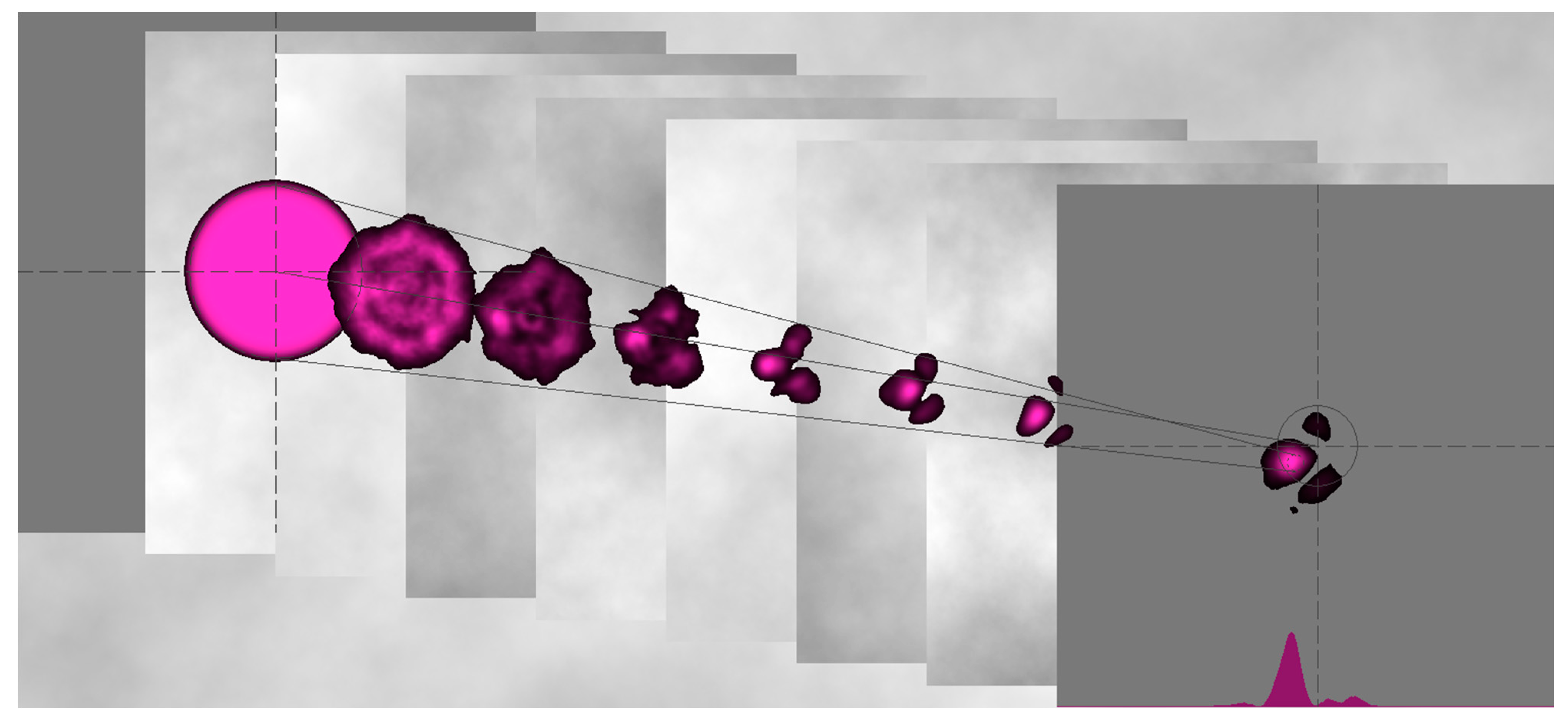
19]. The transport Equation (2) for forced convection caused by wind was solved numerically using the absolutely stable four-point running difference scheme, which allows you to vary the angle of the transfer vector relative to the horizontal. The split-step method used to simulate the propagation in a randomly inhomogeneous medium is illustrated in
Figure 1, which shows the focusing of a single super-Gaussian beam. The transverse plane of the emitter (x, y, 0) is shown in the upper left corner and the focal plane (x, y, L) is shown in the lower right corner. The turbulent phase screens drift from left to right in the transverse wind direction along the horizontal x axis.
To verify the developed software, the calculation results were compared with the known analytical solutions obtained in the additive approximation, which is valid in the region of small perturbations [
20]. The discrepancy between the compared characteristics, such as the effective radius of the beam and the maximum intensity at the focus, is initially small (no more than 5%), but tends to increase with an increase in both the initial beam power density and the structural turbulence constant
Cn2. This behavior in the discrepancy between the results of numerical and analytical solutions is expected and is explained by the fact that the analytical approximation has a limited scope. In particular, it does not describe such distinguishing features of the TB effect as asymmetrical wind shift of the beam as well as the power density saturation effect [
15,
16].
3. Results and Discussion
Thermal blooming limits the focusing of a high-power laser in atmospheric paths. An increase in the initial power density first leads to saturation and then to a decrease in the intensity of the focal spot. Here, we consider the optimization of the initial power density of the emitting aperture, as well as the possibility of scaling the PCBC arrays by increasing the number of channels.
This section discusses (1) the power density optimization for one six-channel array, (2) the influence of mutual orientation of two six-channel PCBC on distortions of TB with crosswind,(3) optimization of power density for three six-channel PCBC arrays, and(4) the final simulations of all the above multichannel PCBC systems on slant atmospheric paths with a length of 2 to 6 km.
The following parameters were chosen as initial for all simulations: structure constant of the refractive index of atmospheric turbulence near the groundCn2 = 5.10−14 m−2/3, absorption coefficient α = 0.1 km−1, ground wind speed V= 3 m/s, transverse wind velocity vector directed horizontal from left to right, trace elevation angles = 25°, 45°. All calculations were performed for the configuration of a six-channel PCBC array. The diameter of each channel beam was set equal to 2a0 = 10 cm, the radiation wavelength λ = 1μm, initial power of each beam channel P0= 3 kW, initial intensity I0= P0/πa02 = 38.2 W/cm2.
3.1. One Six-Channel PCBC Array
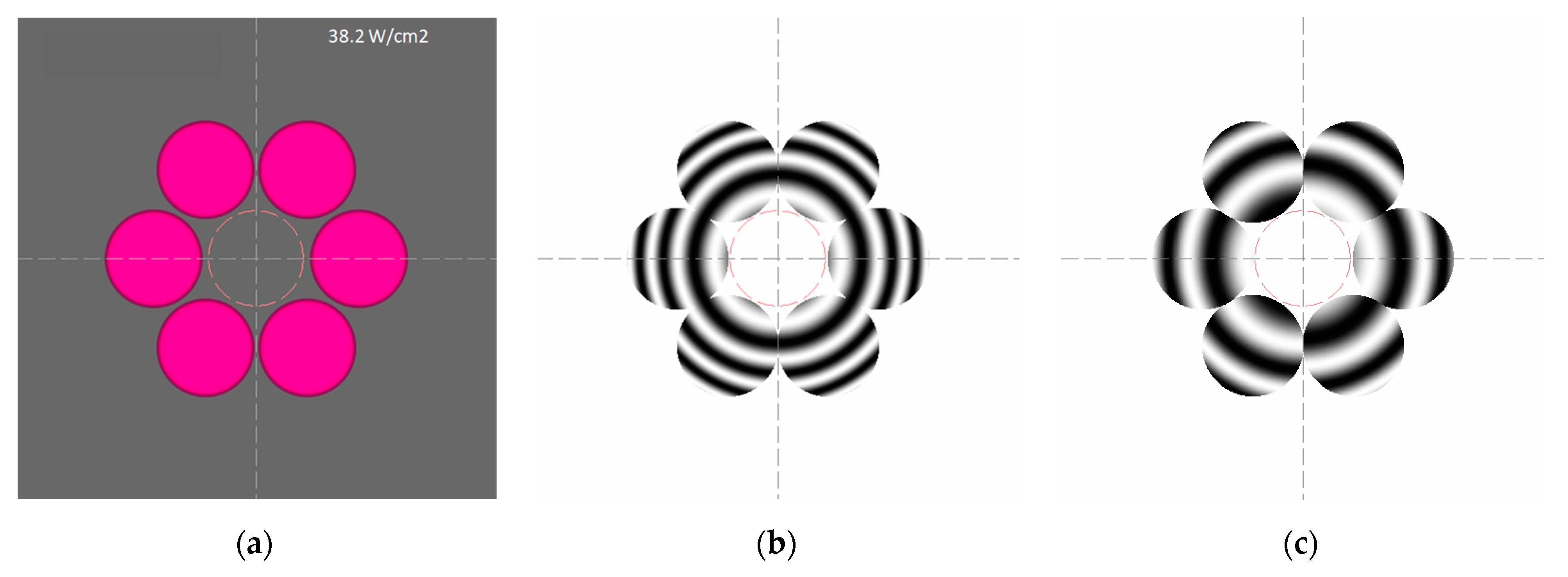
The initial conditions for Equations (1) and (2) were set in the form of an array of super-Gaussian beams. Expression (3) was used with the index value mG = 10, which gives the filling factor value of each aperture close to 1. The intensity distribution of the six-channel system in plane z = 0 is shown in
Figure 2a where the initial intensity (power density W/cm
2) is indicated at the top. The dotted line on the axis in the center shows a region with a size equal to the diameter of a single aperture.
The initial coherent phase of the CBC array is shown in
Figure 2b. To simulate non-coherent PCBC, random phase shifts in the (−π, π) range were added to each channel at every time-step, as shown in
Figure 2c.
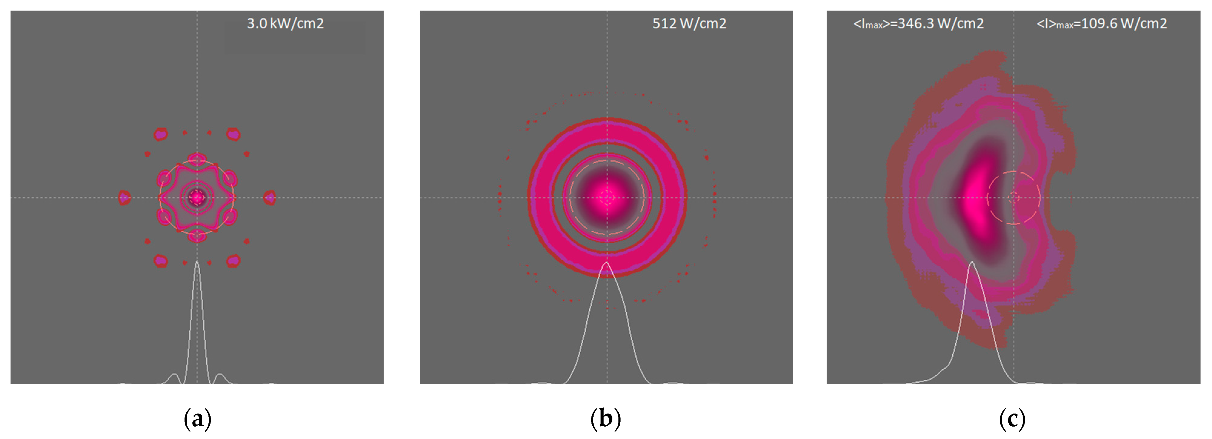
The diffraction patterns of the CBC and PCBC arrays focused at a distance L = 5 km are shown in
Figure 3a,b, respectively. The shown average intensity of PCBC was calculated by the Monte Carlo method by averaging random data over a set of 1000 samples (
Figure 3b). Here and below, two-dimensional intensity distributions are shown on a logarithmic scale and their cross-sections (shown at the bottom of the frame) are shown on a normalized linear scale. Comparing the maximum intensity values on these frames above, it can be noted that the PCBC model leads to a decrease in intensity compared to CBC by a multiple of the number of channels (by a factor of six), as it should be.
Figure 3c shows the average intensity distribution at the CPBS focus at the same distance in a turbulent atmosphere with TB as an example. The time-averaged intensity was calculated by averaging the instantaneous intensity patterns over a time of ~1 s, excluding the transition interval τ = 2a0/v.
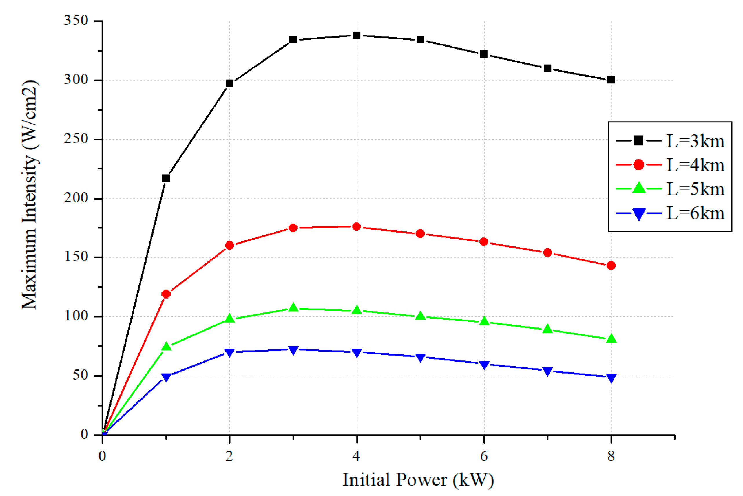
To maximize the beam intensity in thermal blooming, laser systems such as CBC or PCBC can be optimized. For fixed size of emitting aperture, one can find the optimal radiation power at which the value of the maximum beam intensity reaches saturation. Such simulations were carried out for turbulent atmospheric slant paths with an elevation angle of 25° at distances of 3, 4, 5, and 6 km, and the results are presented in
Figure 4.
The dependence of the optimal power value on distance tends to decrease with increasing distance. For all simulation scenarios presented below, the value of 3 kW of the initial power was chosen as optimal. For a radiating aperture with a diameter of 10 cm, this value corresponds to the optimal value of the initial power density (intensity) equal to 38.2 W/cm2.
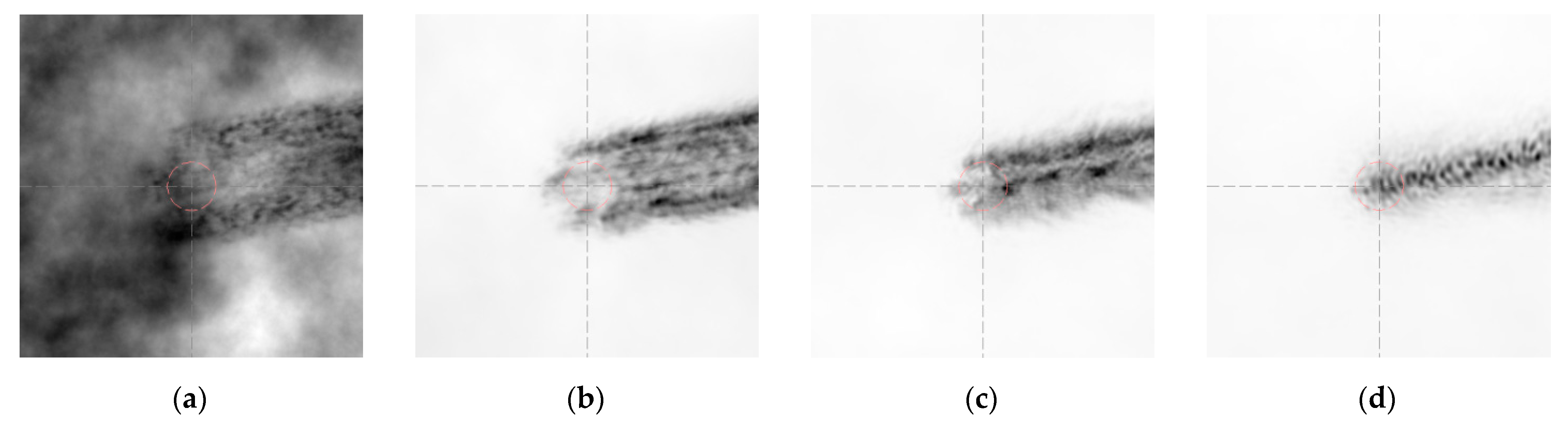
Qualitatively, the process of modeling air heating by a powerful laser beam is illustrated in
Figure 5. Here, the phase distortion tails formed by the TB in the direction of the transverse component of the wind velocity vector are shown at various distances from the radiating aperture along the propagation path. At the beginning of the path, the contribution of turbulent inhomogeneities exceeds the temperature gradients caused by absorption (
Figure 5a). As the distance from the emitter increases, the narrowing of the focused beam leads to an increase in its intensity in the absorption zone and an increase in thermal distortions (
Figure 5b,c), which reach a maximum near the focal plane (
Figure 5d).
3.2. Two Six-Channel PCBC Arrays
Due to the fact that the Earth’s atmosphere is constantly in wind motion, the low probability of the occurrence of stagnant zones along the distant propagation paths makes it possible not to consider their influence [
4]. At the same time, the presence of wind and the beam shift caused by TB can lead to the mutual influence of high-power beam channels in combining systems. To assess the influence of the orientation of beam arrays relative to the wind direction, a focusing system consisting of two six-channel PCBC arrays was considered.
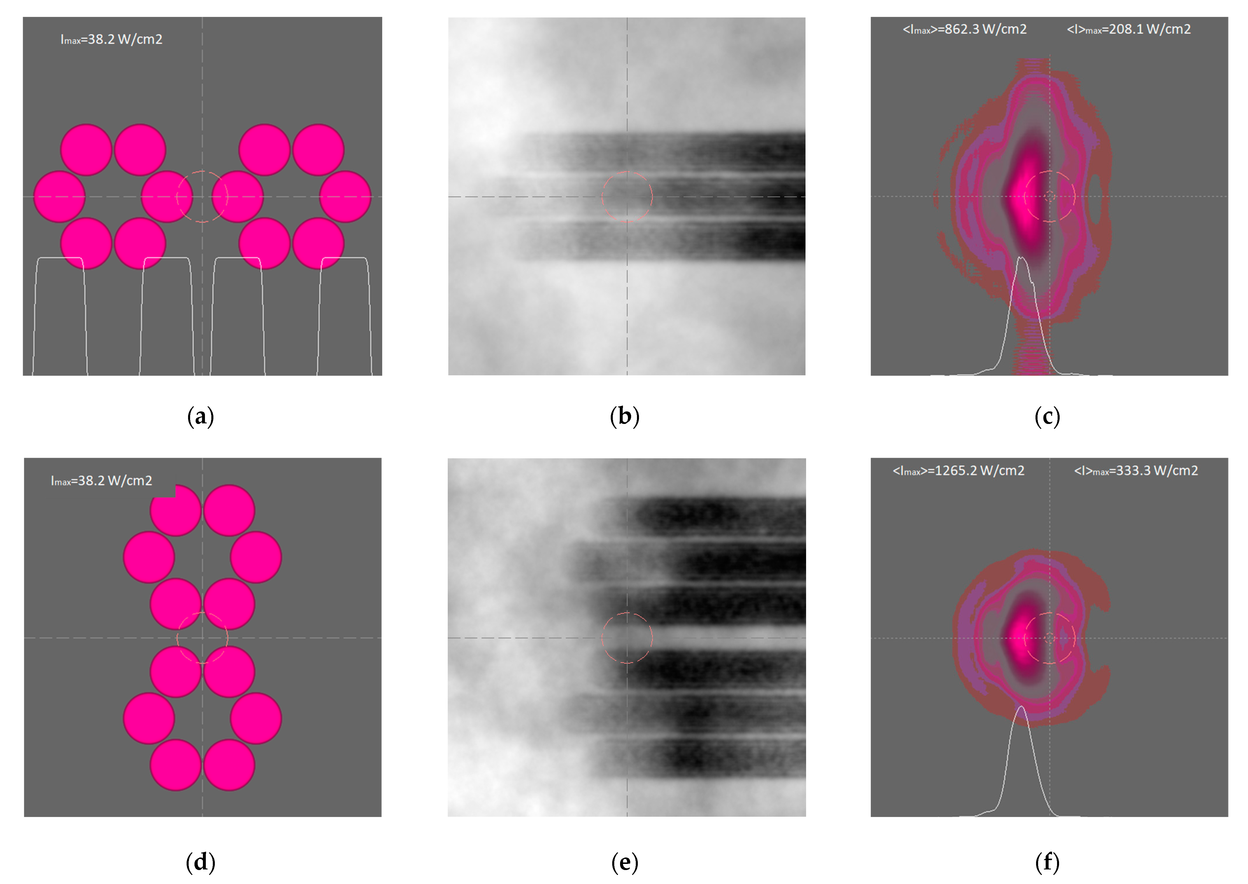
Figure 6 shows the results of PCBC modeling on a slant 5 km path with the elevation angle of 45° for two options for the arrays orientation relative to the transverse wind direction—the longitudinal (above) and transverse (below). In the first case (
Figure 6a), due to the mutual influence of the heating zones by the channels (
Figure 6b), the asymmetric beam broadening is the largest (
Figure 6c), which leads to the worst value of the maximum average intensity <I>
max = 208.1 W/cm
2. In the second variant (
Figure 6d), there is no mutual influence (
Figure 6e), the distribution of the average intensity in the focal spot is more compact (
Figure 6f), and the value <I>
max = 333.3 W/cm
2 increases by 1.6 times compared to the first case.
3.3. Three Six-Channel PCBC Arrays
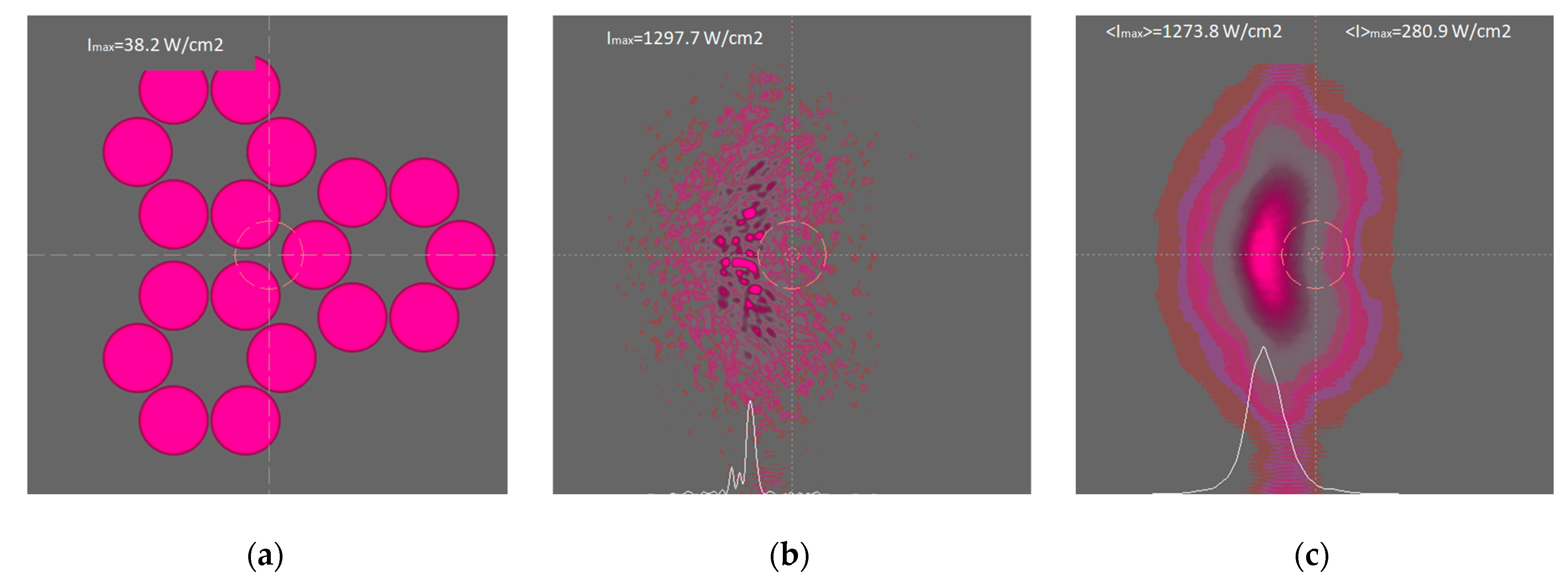
A simulated system configuration of three six-channel PCBC arrays is shown in
Figure 7a. One sample frame from a set of random instantaneous intensity distributions in the cross-section of the focal plane is shown in
Figure 7b. The instant picture is characterized by intensity peaks in the form of bright spikes with a high maximum intensity value (1297.7 W/cm
2 in frame upside). The spikes are the result of atmospheric turbulence, thermal blooming, and random interference of channel beam interactions. This effect of amplification of intensity fluctuations due to TB in comparison with ordinary fluctuations in a turbulent atmosphere is rather complicated and requires separate consideration.
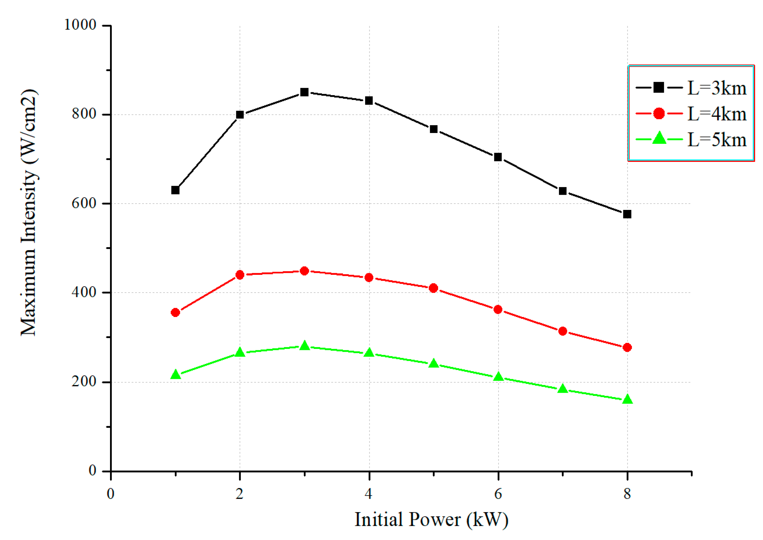
To assess the possible influence of scaling the PCBC system (due to an increase in the number of channels) on the value of the optimal power of one channel, calculations similar to those considered in
Section 3.1 were carried out. From a comparison of
Figure 8 with
Figure 4 it can be seen that the qualitative behavior of the dependence graphs, as well as the value of the optimal power (3 kW) for the considered distances, practically coincide.
The final simulation results of all the above multichannel PCBC systems are presented in
Figure 9. The simulations were carried out for turbulent atmospheric slant paths with a length of 2 to 6 km, an elevation angle of 25°, and the structure characteristic of refractive index near the ground
Cn2 = 5.10
−14 m
−2/3.
The graphs presented in
Figure 9 show an inversely proportional dependence of the maximum average intensity in the focal plane on the distance and a directly proportional dependence on the number of channels with the tendency to slow down the relative increase in intensity.
4. Conclusions
The results of numerical simulations show a significant impact of thermal and turbulent distortions on the focusing of multichannel PCBC arrays. The maximum average intensity of the focused beam array drops rapidly with increasing distance to target inversely proportion to the path length.
Simulation of high-power laser beam propagation in a turbulent atmosphere shows that it is possible to calculate the optimal initial power density of the emitting aperture, at which the value of the maximum intensity at the focus reaches its maximum (the resulting increment can reach up to 30%).
The mutual influence of beams in a multichannel system due to TB with crosswind leads to additional losses of the average intensity, which can be optimized by choosing the initial configuration of the PCBC (1.6 times magnification factor obtained). When bringing several high-power beams into focus, the interaction of turbulence and TB causes the appearance of strong spikes of power density, which leads to an additional amplification of its fluctuations.
Scaling the initial power in multichannel PCBC arrays preserves the proportional dependence of focal spot intensity with an increase in the number of channels. The relative increase in intensity tends to slow down with an increase in the number of beams in the PCBC.
The development of multichannel laser systems designed to operate in the atmosphere requires further research and simulations. The effect of enhancement of intensity fluctuations due to the turbulence–TB interaction is quite complex and requires separate consideration.
Author Contributions
Conceptualization, P.K. and V.L.; methodology, P.K.; software, P.K.; validation, P.K. and V.L.; formal analysis, P.K.; investigation, P.K.; resources, V.L.; data curation, V.L.; writing—original draft preparation, P.K.; writing—review and editing, P.K. and V.L.; visualization, P.K.; supervision, V.L.; project administration, V.L.; funding acquisition, V.L. All authors have read and agreed to the published version of the manuscript.
Funding
The work was carried out within the framework of the state task of the Institute of Atmospheric Optics of the Siberian Branch of the Russian Academy of Sciences FWRU-2021-0003.
Institutional Review Board Statement
Not applicable.
Informed Consent Statement
Not applicable.
Data Availability Statement
Not applicable.
Conflicts of Interest
The authors declare no conflict of interest. The funders had no role in the design of the study; in the collection, analyses, or interpretation of data; in the writing of the manuscript; or in the decision to publish the results.
References
- Andrews, L.C.; Phillips, R.L. Laser Beam Propagation through Random Media, 2nd ed.; SPIE Press: Bellingham WA, USA, 2005; pp. 1679–1714. [Google Scholar] [CrossRef]
- Gebhardt, F.G. High power laser propagation. Appl. Opt. 1976, 15, 1479–1493. [Google Scholar] [CrossRef] [PubMed]
- Smith, D.C. High-power laser beam propagation: Thermal blooming. Proc. IEEE 1977, 65, 1679–1714. [Google Scholar] [CrossRef]
- Fleck, J.A.; Morris, J.R.; Feit, M.D. Time-dependent Propagation of High Energy Laser Beams through the Atmosphere. Appl. Phys. 1976, 10, 129–160. [Google Scholar] [CrossRef]
- Konyaev, P.A.; Lukin, V.P. Thermal distortions of focused laser beams in the atmosphere. Appl. Opt. 1985, 24, 415–421. [Google Scholar] [CrossRef] [PubMed]
- Li, Y.; Qian, L.; Lu, D.; Fan, D.; Wen, S. Coherent and incoherent combining of fiber array with hexagonal ring distribution. Opt. Laser Technol. 2007, 39, 957–963. [Google Scholar] [CrossRef]
- Vorontsov, M.; Lachinova, S. Laser beam projection with adaptive array of fiber collimators. I. Basic Considerations for analysis. J. Opt. Soc. Am. A 2008, 25, 1949–1959. [Google Scholar] [CrossRef] [PubMed]
- Vorontsov, M.; Filimonov, G.; Ovchinnikov, V.; Polnau, E.; Lachinova, S.; Weyrauch, T.; Magnano, J. Comparative efficiency analysis of fiber-array and conventional beam director systems in volume turbulence. Appl. Opt. 2016, 55, 170–185. [Google Scholar] [CrossRef] [PubMed]
- Pu, Z.; Zejing, L.; Xiaojun, X.; Zilun, C. Numerical analysis of the effects of aberrations on coherently combined fiber laser beams. Appl. Opt. 2008, 47, 3350–3359. [Google Scholar] [CrossRef]
- Goodno, G.D.; Shih, C.C.; Rothenberg, J.E. Perturbative analysis of coherent combining efficiency with mismatched lasers. Opt. Express 2010, 20, 25403–25414. [Google Scholar] [CrossRef] [PubMed]
- Weyrauch, T.; Vorontsov, M.; Magnano, J.; Ovchinnikov, V.; Bricker, D.; Polnau, E.; Rostov, A. Deep turbulence effects mitigation with coherent combining of 21 laser beams over 7 km. Opt. Lett. 2016, 41, 840–843. [Google Scholar] [CrossRef] [PubMed]
- Jabczynski, J.; Gontar, P. Effect of beam profile and partial coherence on coherent beam combining performance. Opt. Comm. 2019, 42, 40–45. [Google Scholar] [CrossRef]
- Sprangle, P.; Penamo, J.; Fischer, R.; Hafizi, B. Incoherent Combining and Atmospheric Propagation of High-Power Fiber Lasers for Directed-Energy Applications. IEEE J. Quantum Electron. 2009, 45, 138–148. [Google Scholar] [CrossRef]
- Sprangle, P.; Hafizi, B.; Ting, A.; Fischer, R. High-power lasers for directed-energy applications. Appl. Opt. 2015, 54, F201–F209. [Google Scholar] [CrossRef] [PubMed]
- Spencer, M.F. Wave-optics investigation of turbulence thermal blooming interaction: I. Using steady-state simulations. Opt. Eng. 2020, 59, 081804. [Google Scholar] [CrossRef]
- Spencer, M.F. Wave-optics investigation of turbulence thermal blooming interaction: II. Using time-dependent simulations. Opt. Eng. 2020, 59, 081805. [Google Scholar] [CrossRef]
- Fathi, H.; Närhi, M.; Gumenyuk, R. Towards ultimate high-power scaling: Coherent beam combining of fiber lasers. Photonics 2021, 8, 566. [Google Scholar] [CrossRef]
- Hettel, W.; Meinhold, P.; Suen, J.; Srinivasan, P.; Krogen, P.; Wirth, A.; Lubin, P. Beam propagation simulation of phased laser arrays with atmospheric perturbations. Appl. Opt. 2021, 60, 5117–5123. [Google Scholar] [CrossRef] [PubMed]
- Konyaev, P.A.; Lukin, V.P. Computation algorithms for simulation in atmospheric optics. Appl. Opt. 2016, 12, B107–B112. [Google Scholar] [CrossRef] [PubMed]
- Asanov, S.V.; Geintz, Y.E.; Zemlyanov, A.A.; Ignatyev, A.B. Forecast of intense near- and mid-IR laser radiation propagation along slant atmospheric paths. Atmos. Ocean. Opt. 2016, 29, 315–323. [Google Scholar] [CrossRef]
| Disclaimer/Publisher’s Note: The statements, opinions and data contained in all publications are solely those of the individual author(s) and contributor(s) and not of MDPI and/or the editor(s). MDPI and/or the editor(s) disclaim responsibility for any injury to people or property resulting from any ideas, methods, instructions or products referred to in the content. |
© 2023 by the authors. Licensee MDPI, Basel, Switzerland. This article is an open access article distributed under the terms and conditions of the Creative Commons Attribution (CC BY) license (https://creativecommons.org/licenses/by/4.0/).

