Communication

Hadamard Single-Pixel Imaging Based on Positive Patterns

1
Faculty of Intelligent Manufacturing, Wuyi University, Jiangmen 529020, China
2
School of Electrical, Computer and Telecommunications Engineering, University of Wollongong, Wollongong 2522, Australia
*
Author to whom correspondence should be addressed.
Photonics 2023, 10(4), 395; https://doi.org/10.3390/photonics10040395
Submission received: 9 February 2023 / Revised: 16 March 2023 / Accepted: 30 March 2023 / Published: 2 April 2023
(This article belongs to the Topic Ghost Imaging: From Quantum to Artificial Intelligence)

Abstract

:
Hadamard single-pixel imaging (SPI) employs the differential measurement strategy to eliminate the effect of negative value of Hadamard basis patterns but leads to doubling the number of measurements. To reduce the number of measurements, a Hadamard SPI method based on positive patterns is proposed. In this method, only the positive patterns are used to acquire measurement values and reconstruct images, so the number of measurements will be reduced by 1/2. Combined with the intensity correlation theory of ghost imaging, the average value of the acquired measures is found; this average value is subtracted from all the measurement values to obtain the spectral coefficients, thus the background noise is eliminated to ensure the imaging quality. Simulation and experimental results show that the proposed method has good noise robustness and can efficiently reconstruct high quality images.

1. Introduction

Single-pixel imaging (SPI) [1,2] originated from quantum ghost imaging [3] and is an indirect imaging method. Unlike traditional direct imaging methods that use multiple pixel detectors, SPI uses a single-pixel detector to collect the transmitted or reflected light intensity of an object and then uses the light intensity with the illumination pattern to reconstruct the object image. Generally, SPI has two kinds of devices, in the first one, a spatial light modulator (SLM) is placed between the object and the detector, while in the second one, the modulation device is placed between the light source and the object, which is also known as computational ghost imaging [4]. Essentially, SPI and computational ghost imaging are based on the same principles and can use the same reconstruction algorithms. Compared with conventional imaging methods, SPI has advantages in non-visible and low-light imaging, is robust to light scattering, and has been widely used in 3D imaging [5,6,7], terahertz imaging [8,9,10], X-ray imaging [11,12,13,14], multispectral imaging [15,16], scattering medium imaging [17,18], LIDAR [19,20], and gas detection [21] fields. However, SPI requires the projection of a series of illumination patterns to reconstruct the image, a process that is time-consuming.
To overcome this drawback, the compressed sensing (CS) algorithm is used in SPI to reduce the number of measurements. Compressed sensing single-pixel imaging (CS-SPI) can restore the image under sub-Nyquist sampling and reduce the measurement time, but the imaging quality decreases as the number of measurements is further reduced. To ensure the imaging quality, researchers have proposed SPI methods based on orthogonal illumination patterns [22,23,24,25,26,27,28,29,30,31,32]. Compared with using random illumination patterns, orthogonal illumination patterns can achieve high quality reconstruction. Hadamard basis patterns, Fourier basis patterns, and discrete cosine basis patterns are typical of orthogonal illumination patterns. Hadamard basis patterns are binary patterns with only “+1” and ”−1”. The Hadamard SPI uses the Hadamard basis pattern for imaging, and since the modulator cannot load negative elements, a differential measurement strategy is required to split the Hadamard basis pattern into two patterns containing only “+1” and “0” elements. Therefore, for an N × N pixels image, the full sampling number is 2 N 2 . Unlike the Hadamard basis pattern, the Fourier basis pattern and the discrete cosine basis pattern are both grayscale patterns, and both basis patterns also include negative elements, so a differential measurement strategy is also required in the Fourier SPI and discrete cosine SPI methods, and the number of full samples is also 2 N 2 for an N × N pixel image. If the modulation device used in the experiment is a digital micromirror device (DMD), it is also necessary to convert the grayscale pattern to a binary pattern because the DMD cannot directly load the grayscale pattern, which will lead to poor image quality or consume more measurements, so Hadamard SPI is more suitable for the real environment.
In order to reduce the number of measurements of Hadamard SPI, this paper proposes a Hadamard SPI method based on positive patterns. Compared with existing differential measurement strategies, the proposed method uses only positive patterns to reconstruct images, which exploits the complementary properties of positive and negative patterns, and thus reduces the number of measurements by 1/2. At the same time, the proposed method combines differential measurement strategies with ghost imaging theory, thus eliminating environmental noise while obtaining Hadamard spectral coefficients. The proposed method can achieve high quality imaging in a noisy environment and significantly reduces the number of measurements compared with existing methods. Simulation and experimental results validate the effectiveness of the proposed method, which provides a new strategy for achieving high-quality and real-time single-pixel imaging.
The remaining sections of this paper are organized as follows. Section 2 presents the principles of the proposed method. Section 3 shows the simulation and experimental results. Section 4 presents the discussion of our experimental results. Section 5 concludes the whole paper.

2. Methods

A M × M Hadamard basis pattern P ( x , y ; u , v ) can be obtained by applying an Inverse Hadamard Transform (IHT) to a delta function δ ( u , v ) ,
P ( x , y ; u , v ) = H 1 { δ ( u , v ) }
where ( x , y ) is the coordinate in the spatial domain and ( u , v ) is the coordinate in the Hadamard domain, H 1 { } denotes an IHT, and
δ ( u , v ) = { 1 , u = u 0 , v = v 0 0 , otherwise
In the initial basis pattern P ( x , y ; u , v ) , the element values are “+1” and “−1”, but the DMD cannot modulate the negative light intensity values. On the other hand, the background illumination may generate noise and reduce the reconstruction quality, so it needs to be solved by the differential measurement method. Dividing P ( x , y ; u , v ) into two patterns: positive pattern P + ( x , y ; u , v ) and negative pattern P ( x , y ; u , v ) , satisfies the following relationship:
P ( x , y ; u , v ) = P + ( x , y ; u , v ) P ( x , y ; u , v )
where
P + ( x , y ; u , v ) = [ 1 + H 1 { δ ( u , v ) } ] / 2
P ( x , y ; u , v ) = [ 1 H 1 { δ ( u , v ) } ] / 2
Subsequently, the illumination pattern is projected onto the target scene, and a series of different voltage signals are detected using a single-pixel detector and recorded using a data acquisition (DAQ) device. The reflective modulation signal can be expressed as:
D ( u , v ) = E + k x = 0 M 1 y = 0 M 1 O ( x , y ) P ( x , y ; u , v )
where k is a scale factor whose value is determined by the size and position of the detector’s detection surface; O ( x , y ) is the target object; and E represents the detector’s response to the background light.
After performing the differential operation on the above equation, the following equation is obtained:
D H ( u , v ) = D + ( u , v ) D ( u , v ) = k x = 0 M 1 y = 0 M 1 O ( x , y ) P + ( x , y ; u , v ) k x = 0 M 1 y = 0 M 1 O ( x , y ) P ( x , y ; u , v )
where D + ( u , v ) is called the positive coefficient and D ( u , v ) is called the negative coefficient. According to Equation (7), each spectral coefficient of the reconstructed image is obtained and the ambient noise is eliminated. Then, the reconstructed image can be obtained by using IHT on the spectrum. However, this differential measurement method doubles the number of measurements.
Considering the complementary properties of positive and negative patterns and adding the positive and negative coefficients in the ideal environment, we have:
D + ( u , v ) + D ( u , v ) = x = 0 M 1 y = 0 M 1 O ( x , y ) P + ( x , y ; u , v ) + x = 0 M 1 y = 0 M 1 O ( x , y ) P ( x , y ; u , v ) = x = 0 M 1 y = 0 M 1 O ( x , y ) 1 = D H ( 0 , 0 )
Equation (8) shows that the sum of the positive coefficient and its corresponding negative coefficient is the spectral coefficients corresponding to the all-one matrix, and substituting Equation (8) into Equation (7), we have:
D H ( u , v ) = 2 D + ( u , v ) D H ( 0 , 0 ) = 2 k x = 0 M 1 y = 0 M 1 O ( x , y ) P + ( x , y ; u , v ) D H ( 0 , 0 ) + E
Equation (9) shows that all spectral coefficients can be obtained equally by all Hadamard positive patterns. However, considering the noise factor, Equation (9) cannot eliminate the ambient noise as the differential measurement, which will affect the reconstructed image results. Ref. [33] proposes a filtering method to eliminate the noise in the spectral components obtained by Equation (9), but this method increases the complexity of image reconstruction.
From the ghost imaging intensity correlation algorithm, it is known that the detection value is subtracted from the average of all measurements to obtain a high-contrast image. Inspired by this property, D H ( 0 , 0 ) is replaced by 2 D ¯ , and D ¯ = u = 0 M 1 v = 0 M 1 D H ( u , v ) / M 2 represents the average of all measurements, so that Equation (9) can be expressed as:
D H ( u , v ) = 2 D + ( u , v ) 2 D ¯ = 2 [ k x = 0 M 1 y = 0 M 1 O ( x , y ) P + ( x , y ; u , v ) D ¯ ]
With Equation (10), the spectral coefficients of the object can be obtained with the positive pattern only, while eliminating the ambient noise. The method is also applicable to negative patterns, which are not discussed here.
Finally, the IHT is used to reconstruct the target image, and the reconstruction equation can be expressed as:
I O = H 1 { D H }
where I O denotes the reconstructed image; D H is the spectrum composed of spectral coefficients.
The proposed method can be summarized as the following four steps:
(1) Calculating and generating a series of positive patterns.
(2) Loading the illumination patterns onto the spatial light modulator to modulate the object in turn, measuring the reflected light intensities with a single-pixel detector.
(3) Generating the Hadamard spectrum based on the measured intensities by (10).
(4) Reconstructing the image by (11).
The above process is shown in Figure 1.

3. Results

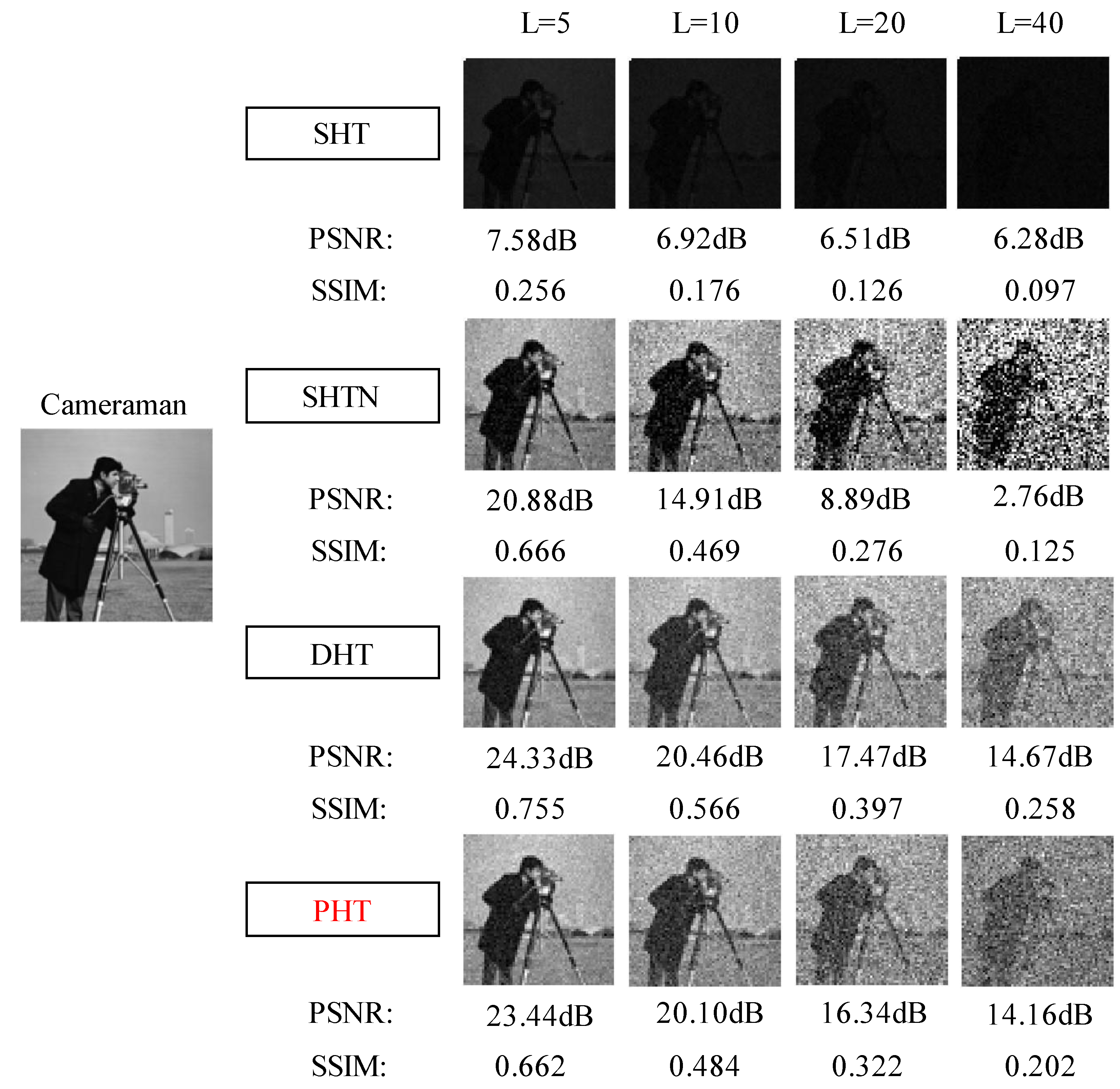
3.1. Simulation Results

To test the imaging performance of the proposed method, single-step Hadamard transform single-pixel imaging (SHT), single-step Hadamard transform single-pixel imaging after noise suppression (SHTN) [33], and differential Hadamard transform single-pixel imaging (DHT) [27] are used for comparison with the proposed positive Hadamard transform single-pixel pixel imaging (PHT). In this case, all the above methods use the inverse Hadamard transform for image reconstruction. Under-sampling and full-sampling simulations are performed using an image (Cameraman) with a resolution of 64 × 64 pixels as the simulation object. The number of measurements required for a 100% sampling rate is defined here as 4096. Since the DHT method requires eliminating the “−1” element from the Hadamard matrix, the number of measurements is doubled, and the number of measurements at full sampling is 8192, corresponding to a sampling rate of 200%. Peak signal-to-noise ratio (PSNR) and structural similarity index (SSIM) are used to evaluate the image quality. Higher values indicate better reconstruction.
The PSNR is calculated by the formula:
PSNR = 10 log 10 { M A X 2 1 / M N i = 1 M j = 1 N [ I 0 ( i , j ) I ( i , j ) ] 2 }
where I 0 is the original image of the target scene, consisting of M × N pixels, I is the reconstructed image and M A X = 1 is the maximum pixel value of the double-type image. SSIM is calculated by
SSIM ( x , y ) = ( 2 μ x μ y + c 1 ) ( 2 δ x y + c 2 ) ( μ x 2 + μ y 2 + c 1 ) ( δ x 2 + δ y 2 + c 2 )
where x is the original image; y is the reconstructed image; μ x and μ y are the mean values of the original image and the reconstructed image, respectively; δ x y is the covariance of x and y ; δ x 2 and δ y 2 are the variances of x and y , respectively; c 1 and c 2 are two constants that avoid zero denominators.
The simulation results for Cameraman images are shown in Figure 2. From the images, DHT recovered images with severe mosaicization under low sampling rates; this is because it requires twice the number of measurements compared with other methods. SHT, SHTN, and PHT benefited from the low number of measurements and had better image quality at all sampling rates. From the comparison of quantitative results, the PSNR values and the SSIM values of recovered images by DHT are all lower than those of SHT, SHTN, and PHT. The quantitative results of recovered images by SHT are the same as SHTN, except at a 100% sampling rate. The quantitative results of recovered images by PHT are approximately the same as SHT and SHTN.
Furthermore, the noise robustness of the proposed method to noise is investigated by simulating a real environment and applying noise to the measured values. First, we add white Gaussian noise to the raw data. The addition of white Gaussian noise is implemented by using the built-in function awgn() of MATLAB(9.8.0.1323502 (R2020a), creator: sunrui, location: Jiangmen, China). The DHT, single-step Hadamard transform single-pixel imaging (SHT), and single-step Hadamard transform single-pixel imaging after noise suppression (SHTN) [33] are compared with the proposed method under full sampling conditions. The results are shown in Figure 3. The noise robustness of the proposed PHT is worse than that of DHT but better than that of SHTN and SHT.
Then, to simulate random noise in the environment, we add random noise to the raw data. The fundamental noise is first generated using the rand() function of MATLAB and then multiplied by 5×, 10×, 20×, and 40×, respectively. The results are shown in Figure 4. The noise robustness of the proposed PHT is worse than that of DHT but better than that of SHTN, and the SHT method is almost impossible to image in the noise case.

3.2. Experimental Results

In order to verify the effectiveness of the proposed method, practical experiments are carried out. The experimental system is shown in Figure 5, using a white LED as the light source and a printed USAF resolution image with a toy duck as the imaging object. The generated Hadamard patterns are loaded by a DMD (ViALUX V-9601, 1920 × 1200), and the refresh rate of the DMD is set to 16,384 Hz. Since the resolution of the DMD is 1920 × 1200, a series of 128 × 128 pixels Hadamard patterns are upsampled to form a 1024 × 1024 pixels pattern.
The modulated light intensity signal is received by a photodetector (Thorlabs PDA100A), and a data acquisition card (NI USB-6366) converts the light signal into a digital signal that can be processed by a computer, which is the measured light intensity value that makes up the Hadamard transform spectrum of the image, and finally IHT is performed to reconstruct the image. Using the experimental system described above, SHT, SHTN, and DHT are compared with the proposed PHT method using sampling rates of 5%, 10%, 15%, and 20%.
The image reconstruction results are shown in Figure 6. We can see that SHT is not able to obtain the reconstructed images at all four sampling rates because of high noise. Despite the fact that partial noise is removed by SHTN, the contrast of re-constructed image is still poor, which confirms the results in ref. [34]. DHT and PHT can obtain good images at all four sampling rates, which means both methods have good noise robustness. From the quantitative analysis results, we can conclude that the proposed PHT method shows better performance compared with the other three methods, which is consistent with the analysis of the simulation results and indicates that the proposed method has good imaging efficiency when applied to the actual SPI system.

4. Discussion

We have developed a PHT SPI method. In contrast to existing Hadamard SPI methods [25,33], the proposed method is derived from the classical differential measurement strategy theory, which firstly exploits the complementarity of positive and negative patterns, and secondly combines the averaging property in the ghost imaging intensity correlation algorithm. Therefore, the PHT method can achieve high-quality imaging in a noisy environment, and significantly reduce the number of measurements.
However, it is also clear that the PHT reduces the number of measurements by half compared with the DHT, but the noise robustness is weaker than the DHT. This indicates that the number of measurements and the noise robustness are interacted. In future research, it will be critical to improve the noise robustness of PHT, which will facilitate the application of the method in various environments.
As a new method, PHT has a broad application scope. Besides the results demonstrated in this work, the principle of PHT is readily applicable to improve imaging speed, such as in 3D imaging [7] and multispectral imaging [16] in SPI.

5. Conclusions

In this paper, a Hadamard single-pixel imaging method based on positive patterns is proposed. In this method, the image can be reconstructed using only positive patterns by exploiting the complementarity of Hadamard base patterns and the intensity correlation theory of ghost imaging. The proposed method has both good noise robustness and reduces the number of measurements by half compared with differential measurement and single-step measurement strategies. Simulation and experimental results demonstrate the effectiveness of the method. The method can be widely applied to single-pixel imaging of static and dynamic targets.

Author Contributions

Conceptualization, R.S. and Y.D.; methodology, R.S. and Y.D.; software, R.S. and J.K.; validation, R.S. and J.K.; formal analysis, R.S. and J.K.; investigation, R.S. and J.K.; resources, J.L., Y.D. and J.X.; data curation, R.S. and J.K.; writing—original draft preparation, R.S.; writing—review and editing, R.S. and Y.D.; visualization, R.S. and Y.D.; supervision, J.L., Y.D. and J.X.; project administration, J.L., Y.D. and J.X.; funding acquisition, J.L., Y.D. and J.X. All authors have read and agreed to the published version of the manuscript.

Funding

This work was supported by the National Natural Science Foundation of China (Grant No. 62075168), the Key Scientific Research Platforms and Projects of Ordinary Universities in Guangdong Province (Grant No. 2021KCXTD051), and Wuyi University Hong Kong-Macau Joint Reasearch Funding (Grant No.2021WGALH17).

Institutional Review Board Statement

Not applicable.

Informed Consent Statement

Not applicable.

Data Availability Statement

The data presented in this study are available on reasonable request from the corresponding author.

Conflicts of Interest

The authors declare no conflict of interest.

References

  1. Duarte, M.F.; Davenport, M.A.; Takhar, D.; Laska, J.N.; Sun, T.; Kelly, K.F.; Baraniuk, R.G. Single-pixel imaging via compressive sampling. IEEE Signal Process. Mag. 2008, 25, 83–91. [Google Scholar] [CrossRef] [Green Version]
  2. Edgar, M.P.; Gibson, G.M.; Padgett, M.J. Principles and prospects for single-pixel imaging. Nat. Photonics 2018, 13, 13–20. [Google Scholar] [CrossRef]
  3. Pittman, T.B.; Shih, Y.H.; Strekalov, D.V.; Sergienko, A.V. Optical imaging by means of two-photon quantum entanglement. Phys. Rev. A 1995, 52, R3429–R3432. [Google Scholar] [CrossRef]
  4. Shapiro, J.H. Computational ghost imaging. Phys. Rev. A 2008, 78, 061802. [Google Scholar] [CrossRef]
  5. Sun, B.; Edgar, M.P.; Bowman, R.; Vittert, L.E.; Welsh, S.; Bowman, A.; Padgett, M.J. 3D Computational Imaging with Single-Pixel Detectors. Science 2013, 340, 844–847. [Google Scholar] [CrossRef] [Green Version]
  6. Sun, M.-J.; Edgar, M.P.; Gibson, G.M.; Sun, B.; Radwell, N.; Lamb, R.; Padgett, M.J. Single-pixel three-dimensional imaging with time-based depth resolution. Nat. Commun. 2016, 7, 12010. [Google Scholar] [CrossRef]
  7. Qian, Y.; He, R.; Chen, Q.; Gu, G.; Shi, F.; Zhang, W. Adaptive compressed 3D ghost imaging based on the variation of surface normals. Opt. Express 2019, 27, 27862–27872. [Google Scholar] [CrossRef]
  8. Stantchev, R.I.; Yu, X.; Blu, T.; Pickwell-MacPherson, E. Real-time terahertz imaging with a single-pixel detector. Nat. Commun. 2020, 11, 2535. [Google Scholar] [CrossRef]
  9. Chan, W.L.; Charan, K.; Takhar, D.; Kelly, K.F.; Baraniuk, R.G.; Mittleman, D.M. A single-pixel terahertz imaging system based on compressed sensing. Appl. Phys. Lett. 2008, 93, 121105. [Google Scholar] [CrossRef] [Green Version]
  10. Stantchev, R.I.; Sun, B.; Hornett, S.M.; Hobson, P.A.; Gibson, G.M.; Padgett, M.J.; Hendry, E. Noninvasive, near-field terahertz imaging of hidden objects using a single-pixel detector. Sci. Adv. 2016, 2, e1600190. [Google Scholar] [CrossRef] [Green Version]
  11. Pelliccia, D.; Rack, A.; Scheel, M.; Cantelli, V.; Paganin, D.M. Experimental X-Ray Ghost Imaging. Phys. Rev. Lett. 2016, 117, 113902. [Google Scholar] [CrossRef] [Green Version]
  12. Klein, Y.; Schori, A.; Dolbnya, I.P.; Sawhney, K.; Shwartz, S. X-ray computational ghost imaging with single-pixel detector. Opt. Express 2019, 27, 3284–3293. [Google Scholar] [CrossRef] [PubMed] [Green Version]
  13. Cheng, J.; Han, S. Incoherent Coincidence Imaging and Its Applicability in X-ray Diffraction. Phys. Rev. Lett. 2004, 92, 093903. [Google Scholar] [CrossRef] [PubMed] [Green Version]
  14. Olbinado, M.P.; Paganin, D.M.; Cheng, Y.; Rack, A. X-ray phase-contrast ghost imaging using a single-pixel camera. Optica 2021, 8, 1538–1544. [Google Scholar] [CrossRef]
  15. Edgar, M.P.; Gibson, G.; Bowman, R.; Sun, B.; Radwell, N.; Mitchell, K.J.; Welsh, S.; Padgett, M. Simultaneous real-time visible and infrared video with single-pixel detectors. Sci. Rep. 2015, 5, 10669. [Google Scholar] [CrossRef] [Green Version]
  16. Bian, L.; Suo, J.; Situ, G.; Li, Z.; Fan, J.; Chen, F.; Dai, Q. Multispectral imaging using a single bucket detector. Sci. Rep. 2016, 6, 24752. [Google Scholar] [CrossRef] [Green Version]
  17. Dutta, R.; Manzanera, S.; Gambín-Regadera, A.; Irles, E.; Tajahuerce, E.; Lancis, J.; Artal, P. Single-pixel imaging of the retina through scattering media. Biomed. Opt. Express 2019, 10, 4159–4167. [Google Scholar] [CrossRef]
  18. Katz, O.; Heidmann, P.; Fink, M.; Gigan, S. Non-invasive single-shot imaging through scattering layers and around corners via speckle correlations. Nat. Photonics 2014, 8, 784–790. [Google Scholar] [CrossRef] [Green Version]
  19. Gong, W.; Zhao, C.; Yu, H.; Chen, M.; Xu, W.; Han, S. Three-dimensional ghost imaging lidar via sparsity constraint. Sci. Rep. 2016, 6, 26133. [Google Scholar] [CrossRef] [Green Version]
  20. Radwell, N.; Johnson, S.D.; Edgar, M.P.; Higham, C.F.; Murray-Smith, R.; Padgett, M.J. Deep learning optimized single-pixel LiDAR. Appl. Phys. Lett. 2019, 115, 231101. [Google Scholar] [CrossRef] [Green Version]
  21. Gibson, G.M.; Sun, B.; Edgar, M.P.; Phillips, D.B.; Hempler, N.; Maker, G.T.; Malcolm, G.P.A.; Padgett, M.J. Real-time imaging of methane gas leaks using a single-pixel camera. Opt. Express 2017, 25, 2998–3005. [Google Scholar] [CrossRef]
  22. Sun, M.-J.; Meng, L.-T.; Edgar, M.P.; Padgett, M.J.; Radwell, N. A Russian Dolls ordering of the Hadamard basis for compressive single-pixel imaging. Sci. Rep. 2017, 7, 3464. [Google Scholar] [CrossRef] [PubMed] [Green Version]
  23. Yu, W.K. Super sub-Nyquist single-pixel imaging by means of Cake-Cutting Hadamard basis sort. Sensors 2019, 19, 4122. [Google Scholar] [CrossRef] [PubMed] [Green Version]
  24. Yu, X.; Stantchev, R.I.; Yang, F.; Pickwell-MacPherson, E. Super Sub-Nyquist Single-Pixel Imaging by Total Variation Ascending Ordering of the Hadamard Basis. Sci. Rep. 2020, 10, 9338. [Google Scholar] [CrossRef] [PubMed]
  25. Zhang, Z.; Ma, X.; Zhong, J. Single-pixel imaging by means of Fourier spectrum acquisition. Nat. Commun. 2015, 6, 6225. [Google Scholar] [CrossRef] [PubMed] [Green Version]
  26. Zhang, Z.; Wang, X.; Zheng, G.; Zhong, J. Fast Fourier single-pixel imaging via binary illumination. Sci. Rep. 2017, 7, 12029. [Google Scholar] [CrossRef] [Green Version]
  27. Zhang, Z.; Wang, X.; Zheng, G.; Zhong, J. Hadamard single-pixel imaging versus Fourier single-pixel imaging. Opt. Express 2017, 25, 19619–19639. [Google Scholar] [CrossRef]
  28. Deng, H.; Gao, X.; Ma, M.; Yao, P.; Guan, Q.; Zhong, X.; Zhang, J. Fourier single-pixel imaging using fewer illumination patterns. Appl. Phys. Lett. 2019, 114, 221906. [Google Scholar] [CrossRef]
  29. Zhou, D.; Cao, J.; Cui, H.; Hao, Q.; Chen, B.-K.; Lin, K. Complementary Fourier Single-Pixel Imaging. Sensors 2021, 21, 6544. [Google Scholar] [CrossRef]
  30. Liu, B.-L.; Yang, Z.-H.; Liu, X.; Wu, L.-A. Coloured computational imaging with single-pixel detectors based on a 2D discrete cosine transform. J. Mod. Opt. 2016, 64, 259–264. [Google Scholar] [CrossRef] [Green Version]
  31. Chen, Y.; Liu, S.; Yao, X.-R.; Zhao, Q.; Liu, X.-F.; Liu, B.; Zhai, G.-J. Discrete cosine single-pixel microscopic compressive imaging via fast binary modulation. Opt. Commun. 2020, 454, 124512. [Google Scholar] [CrossRef]
  32. Vaz, P.G.; Amaral, D.; Ferreira, L.F.R.; Morgado, A.; Cardoso, J. Image quality of compressive single-pixel imaging using different Hadamard orderings. Opt. Express 2020, 28, 11666–11681. [Google Scholar] [CrossRef] [PubMed]
  33. Xiao, Y.; Zhou, L.; Chen, W. Direct Single-Step Measurement of Hadamard Spectrum Using Single-Pixel Optical Detection. IEEE Photonics Technol. Lett. 2019, 31, 845–848. [Google Scholar] [CrossRef]
  34. Gao, Z.; Li, M.; Zheng, P.; Xiong, J.; Tang, Z.; Liu, H.-C. Single-pixel imaging with Gao-Boole patterns. Opt. Express 2022, 30, 35923–35936. [Google Scholar] [CrossRef]
Figure 1. The light intensities are collected by the detector after the action of positive patterns with the object, then the light intensity values are formed into a spectrum. Finally, IHT is performed on the spectrum to obtain the reconstructed image.
Photonics 10 00395 g001
Figure 2. Reconstructed images and corresponding PSNRs and SSIMs for the Cameraman image by SHT, SHTN, DHT and PHT at sampling rates between 10% and 200%.
Photonics 10 00395 g002
Figure 3. Reconstructed images and corresponding PSNRs and SSIMs for the Cameraman image by SHT, SHTN, DHT and PHT under different Gaussian noise levels of 0 dB, −10 dB, −20 dB and −30 dB.
Photonics 10 00395 g003
Figure 4. Reconstructed images and corresponding PSNRs and SSIMs for the Cameraman image by SHT, SHTN, DHT and PHT under different random noise levels of 5, 10, 20 and 40.
Photonics 10 00395 g004
Figure 5. Schematic of the experimental system of the proposed method. A white LED illuminates the target, positive Hadamard patterns loaded on the DMD encode the target, then the detector collects the light intensity signals, finally the computer reconstructs the image.
Photonics 10 00395 g005
Figure 6. Reconstructed images and corresponding PSNRs and SSIMs for the test image by SHT, SHTN, DHT and PHT at sampling rates of 5%, 10%, 15% and 20%.
Photonics 10 00395 g006
Disclaimer/Publisher’s Note: The statements, opinions and data contained in all publications are solely those of the individual author(s) and contributor(s) and not of MDPI and/or the editor(s). MDPI and/or the editor(s) disclaim responsibility for any injury to people or property resulting from any ideas, methods, instructions or products referred to in the content.

