Abstract
The continuously growing demand for functional plasmonic devices or systems urges the implementation of economical and accelerated nanostructuring techniques. Laser annealing represents a promising approach to address this challenge, given its widespread usage in industry and research, as well as its unique advantages. This study proposes a scalable, rapid, versatile, and cost-efficient method to grow self-assembled nanostructures on metallic ultrathin films and multilayers, with high precision and patterning freedom. By employing industrial-grade equipment, specifically a 1070 nm nanosecond fiber laser and magnetron sputtering system, we directly grew self-assembled nanoparticles on Ag ultrathin films and AgPd multilayers deposited on Corning glass, via laser annealing at ambient conditions. The self-assembled nanoparticles were formed in designated areas by varying several laser parameters and exhibited intense localized surface plasmon resonances. Optical and structural characterization were realized via UV–Vis spectroscopy and atomic force microscopy, respectively. The plasmonic characteristics were found to depend on the initial film thickness and laser annealing parameters. Laser-treated films exhibited remarkable plasmonic behavior, demonstrating that this method does not lack nanostructuring quality while offering scalability and practicality. Further optimization of the laser settings can refine the process and result in an even faster, cheaper, and more qualitative nanostructuring method.
1. Introduction
Plasmonics is a continuously evolving field that has attracted a lot of research interest in recent years, finding numerous applications in various fields such as optics and photonics, photothermal therapy, energy harvesting, biological and chemical sensing, catalysis, and SERS, as described in [1,2,3,4,5,6,7,8,9,10] and references therein.
More specifically, scientific studies concentrate on plasmonic nanoparticles, which are metallic nanoparticles with diameters much smaller than the wavelength of visible light. These nanostructures exhibit remarkable optical behavior that involves confinement of light and substantial amplification of the local electric field [4,5,6,7,8,11,12,13,14,15,16,17,18].
After irradiation by electromagnetic waves, plasmonic nanoparticles’ free electrons oscillate collectively at a resonant frequency, resulting in a phenomenon known as localized surface plasmon resonance (LSPR). LSPR strongly depends on the composition, size, shape, distribution, and refractive index of the surrounding dielectric environment of plasmonic nanoparticles [1,3,7,8,9,10,11,12,13]. By controlling these structural parameters, one can achieve the desired tuning of LSPRs, but this constitutes a rather challenging process.
One of the most explored noble metals for plasmonic-based applications is silver, due to its low optical losses, its stability in nanoparticle form, and its intense LSRP absorption in the visible spectrum [9,19,20,21]. Additionally, silver has a low cost compared to other noble metals, thus making it an excellent candidate for plasmonic applications [9,22]. Although Au and Ag are mainly considered for their LSPR properties, studies on novel materials in the areas of hydrogen technology and catalysis have also implemented Pt and Pd nanostructures [15,23,24,25,26,27].
The great demand for functional devices and systems that incorporate plasmonic nanostructures requires the development of rapid and cost-efficient plasmonic nanostructuring methods. Various techniques have been used to grow ([28] and references therein) and tune plasmonic nanostructures, with annealing of sputtered thin metallic films being well-established for this purpose [8,11,12,14,15,29,30,31]. However, this method presents significant drawbacks, such as high energy consumption, prolonged treatment time, and minor nanopatterning precision.
An efficient nanostructuring method is laser irradiation or laser annealing of noble metallic thin films [21,28,32,33,34,35,36,37,38,39]. It is a simple, fast, and flexible technique, which provides accurate and adjustable patterning that enables precise plasmonic writing even in 3D specimens. Additionally, this process supports the use of low-cost substrates due to the minimal thermal influence on them (cold process) [9]. With the aforementioned method, nanoparticles can be formed by self-organization due to laser-induced dewetting, a mechanism described thoroughly in the literature [18,40,41,42,43,44,45]. Additionally, it is possible to tune the size and morphology of plasmonic nanoparticles and their LSPR properties (LSPR intensity and position) to some extent, by only configuring the laser parameters [16,21,28,32,33,34,36,37,38,39,46]. Last but not least, laser annealing is an industrial-friendly technique that could potentially support large-scale manufacturing.
Laser annealing by means of an industrial near-IR ns fiber laser can provide faster and more efficient plasmonic nanostructuring in terms of cost and manufacturing practicality, compared to other commercial lasers (CO2, Nd YAG, excimer), without compromises in patterning quality. Fiber laser systems are compact and easy to use, have a high beam quality, wide tunable range, high writing speed, and relatively high output efficiency, and can generate even ultra-short pulses. In addition, optical fibers’ high surface area-to-volume ratio provides great heat dissipation, allowing continuous operation at high-power levels. Fiber lasers are also very reliable, have a long useful life, and require almost no maintenance [47,48,49,50,51].
Concerning laser sources, both pulsed and continuous-wave lasers have been employed to grow self-assembled plasmonic nanoparticles on noble metal thin films (mainly Au and Ag), by utilizing excimer and Nd:YAG lasers operating in the UV, visible, and near-IR spectral region [18,32,33,36,37,44,45]. CO2 lasers operating in the mid-IR range have also been considered, but in these cases, nanoparticle growth occurred due to the thermal energy absorbed initially by the substrate [21,28,34,35]. To our knowledge, there are only two studies [38,39] that have employed near-IR ns pulses by a fiber laser source to directly fabricate plasmonic nanoparticles on noble metallic films and, more specifically, Ag ultrathin films.
In the context of annealing metallic films using pulsed lasers, it is important to consider the principles governing laser–metal interaction with short (ns) and ultra-short (ps or fs) pulsed laser sources. When the intense laser pulse impinges on the metal target, the generated heat that causes the melting of the material is diffused in an area in the vicinity of the molten material, creating the so-called heat-affected zone (HAZ). Upon laser radiation with short pulses (ns), the deposited energy on the material via linear absorption is transferred to the lattice by the excited electrons at the time scale of the laser pulses. During the interaction with the short pulses, the electrons and lattice are in equilibrium. The linear absorption process leads to large melt depths and an extended heat-affected zone. On the other hand, ultra-short pulses (ps or fs) transfer energy from the material via nonlinear processes to the electrons, rather than the lattice, with consequent limited heat conduction and a suppressed HAZ compared to short pulses. Hence, ultra-short pulse (ps or fs) lasers are ideal for the micro/nanofabrication of a wide range of materials in a research environment. On the contrary, in short pulse (ns) lasers, the thermal process dominates the laser pulse—material interaction with a pronounced extended HAZ. Therefore, short pulse lasers (ns), such as the one employed in this work, are the optimal approach to achieve annealing over large areas. Moreover, their lower complexity and cost make them a more practical option for large-scale applications.
In this facile study, the feasibility of an almost unexplored alternative approach was investigated. Here, we demonstrate a laser technique that exploits the capabilities of an industrial ns fiber laser for efficient large-scale plasmonic nanostructuring. More precisely, self-assembled plasmonic nanoparticles were formed directly onto sputtered ultrathin Ag films and AgPd multilayers after nanosecond laser annealing. The process took place at ambient conditions, avoiding intermediate sample preparation and the need for sophisticated equipment that would increase the total manufacturing costs. The plasmonic characteristics of the laser-annealed films and multilayers were examined as a function of the laser frequency, fill spacing, and number of laser passes. Intense plasmonic resonances were obtained, whose positions could be tuned to a certain extent, while the LSPR intensity showed a greater response to variation in the laser settings. Atomic force microscopy revealed self-assembled nanoparticles grown in the irradiated areas whose diameters depend on the initial film thickness and laser settings. For completion purposes, we carried out comparative thermal annealing experiments just for the AgPd multilayers. Finally, in some cases, the laser-annealed films and multilayers exhibited very intense and narrow LSPRs, comparable or even superior to those of other studies that utilized films (or multilayers) of similar thickness [14,15].
2. Materials and Methods
Ultrathin Ag films with thicknesses between 6 and 13.5 nm were deposited via direct-current (DC) magnetron sputtering on Corning glass, at room temperature. The base pressure of the sputter coater device (modified Balzers Union model SCD040, Oerlikon Balzers, Balzers, Liechtenstein) was 2.6 × 10⁻² mbar, achieved using a dual stage rotation pump. During deposition, argon was inserted in the chamber, and the total pressure was kept at values of about 5 × 10⁻² mbar. Concerning the two AgPd multilayers, more precisely the 7.5 nm trilayer and 12.3 nm five-layer multilayers, detailed information on their deposition is provided in [15].
Laser annealing was performed at ambient conditions using a 1070 nm pulsed ytterbium master oscillator power amplifier fiber laser source developed by Sisma SpA, which can deliver 12.5 kW peak power. The laser beam was delivered onto the sample by means of a galvo mirror scanner with a rigid housing and an f-theta lens (f = 100 mm). The laser beam diameter was 15 μm and was defocused by 4.16 mm to avoid thermal damage on the specimens. The irradiated area was 13 × 3.5 mm2. The laser power and pulse duration were 100% and 200 ns, respectively, while the scanning speed was set to 200 mm/s for all cases. The repetition rate (laser frequency), scan line spacing, and laser passes varied. Table 1 shows, in detail, the laser settings for each treated film.

Table 1.
Laser settings for all laser-annealed films and multilayers.
Furthermore, thermal annealing of the AgPd multilayers was carried out in a furnace in atmospheric air. The annealing temperature was 460 °C for all cases, while the annealing time was 5 and 10 min for AgPd #1 and 20 and 40 min for AgPd #2. A muffle furnace was used for the annealing (model Linn elektronik VMK 22).
The optical properties of the treated films and multilayers, both thermally and laser-annealed, were investigated via ultraviolet–visible (UV–Vis) spectroscopy using the Perkin Elmer λ-35 spectrometer instrument working at room temperature in the wavelength range of 200–1100 nm. Eventually, their microstructure was studied via atomic force microscopy (AFM), utilizing a Multimode Microscope with a Nanoscope IIIa controller and a 120 μm × 120 μm magnet-free scanner (Model AS-130 VMF) developed by Digital Instruments (Chapel Hill, NC, USA). The microscope was operated in the non-contact (tapping) mode.
3. Results
The plasmonic characteristics and microstructure of the laser-annealed Ag films and AgPd multilayers were studied. Across the variation in the laser parameters, namely, the fill spacing, laser frequency, and number of laser passes, significant LSPR intensity enhancement and slight tunability were achieved. AFM images revealed the nanostructuring of irradiated areas in different stages. For the AgPd multilayers only, a comparison between thermal and laser annealing was carried out, investigating the influence of both methods on their plasmonic characteristics and microstructure. This comparison is mentioned for completion purposes as well as evidence of fiber laser annealing’s nanostructuring versatility, along with its overall manufacturing practicality and scalability benefits.
3.1. UV–Vis Spectra
UV–Vis spectra were analyzed through background subtraction and subsequent Gaussian fittings of the LSPRs. The background was corrected by subtracting a straight line. Two of the results are indicatively shown in Figure 1a,b. Additionally, the insets show the LSPR position (xc), intensity of the plasmonic response (A), amplitude of the plasmonic resonance (Height), and full width at half maximum (FWHM) of the fitted experimental data, along with their standard errors.
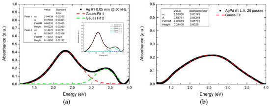
Figure 1.
Indicative absorbance spectra and Gaussian fittings of the LSPRs for Ag films and AgPd multilayers after background subtraction. (a) The area of the Ag #1 (13.5 nm) film irradiated with a fill spacing of 0.05 mm at 50 kHz; the inset concerns the area of the same film irradiated with a fill spacing of 0.0125 mm at 60 kHz. (b) The area of the AgPd #1 (7.5 nm) multilayer irradiated with 20 laser passes. LSPRs are shown to follow a Gaussian curve. Ag films exhibited two main LSPRs, and in some cases, three or even four peaks were visible, as depicted in the inset of (a). This will be discussed further below. AgPd multilayers, however, exhibited only one LSPR, as shown in (b). The LSPR position (xc), intensity of the plasmonic response (A), amplitude of the plasmonic resonance (Height), and full width at half maximum (FWHM) are also presented as insets in both figures.
3.1.1. Ag Ultrathin Films
Fill Spacing Variation
Figure 2 illustrates the UV–Vis absorbance spectra of a 13.5 nm Ag film (Ag #1) plotted as a function of the photon energy for various fill spacing values.
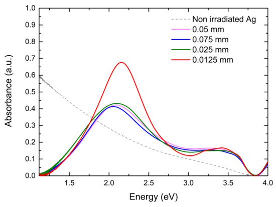
Figure 2.
Absorbance spectra for areas of a 13.5 nm Ag film (Ag #1) irradiated with various fill spacing values at 60 kHz.
The decrease in the fill spacing resulted in a greater overlap of the laser beam and a greater amount of thermal energy being delivered to the film. Absorption curves with one prominent peak around 2.1 eV and one smaller blunt peak around 3.25 eV were observed. With the fill spacing decreasing from 0.075 mm to 0.050 mm, there were no noteworthy changes in the absorption curve, while the further decrease to 0.025 mm led to a slightly higher LSPR amplitude. The LSPR positions for those three fill spacing values were almost identical, with only minor variations present. However, a value of 0.0125 mm induced significant enhancement of the LSPR amplitude for the main peak and resulted in narrower absorption peaks (Figure 3a). Figure 3b,c clearly illustrate this substantial alteration. Furthermore, a minor blue shift was observed for both peaks. Figure 3a–c and Table 2 show the effect of the fill spacing on the LSPR position, amplitude, and full width at half maximum (FWHM) for both peaks. Additionally, in the 0.0125 mm absorption curve, three small peaks are visible in the region of 3.3–3.6 eV. Similar phenomena were observed in all Ag films, and further reference will be made to them in the Discussion section.
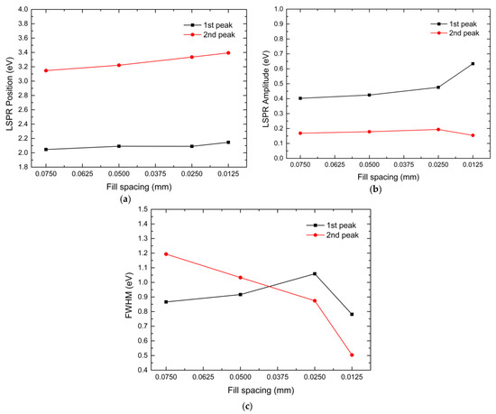
Figure 3.
Graphic illustrations of the LSPR characteristics of a 13.5 nm Ag film (Ag #1), as a function of the fill spacing. The main figures show the data for the main peaks, while the insets show the data for the secondary peaks. (a) LSPR position; (b) LSPR amplitude; (c) FWHM. No FWHM data could be extracted for the secondary peaks.

Table 2.
LSPR characteristics as a function of the fill spacing. It must be noted that all measurements presented in the table were carried out at a laser frequency of 60 kHz.
Frequency Variation
For the same 13.5 nm film (Ag #1), the effect of the laser frequency on its plasmonic behavior was also examined. Due to the limited space on the film, only one comparison is discussed in this case. Specifically, for a 0.05 mm fill spacing, the laser frequency was decreased to 50 kHz and resulted in a blue-shifted absorption curve, with two pronounced peaks, as shown in Figure 4. The LSPR amplitude was slightly lower for the first peak, while it was higher for the second peak. The lower laser frequency caused the thermal energy to penetrate deeper into the film surface, revealing a bimodal distribution of nanoparticles, which accounts for the two broad absorption peaks.
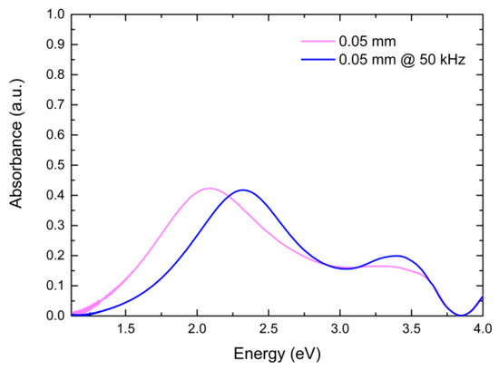
Figure 4.
Absorbance spectra for areas of a 13.5 nm Ag film (Ag #1) irradiated with different laser frequency values.
At this point, it should be mentioned that for the rest of the analysis, the fill spacing value was set to 0.0125 mm, as shown in Table 1.
Figure 5a shows the plasmonic behavior of a 12.5 nm Ag film (Ag #2) as a function of the laser frequency. With increasing frequency, the absorption curves demonstrated a blue shift that was consistent with the main resonance. Additionally, the lower-frequency curves exhibited a minor blue shift (data table shows the opposite; we should consider the errors) as well as a slightly higher LSPR amplitude regarding their secondary peaks. All main peaks were of similar amplitude, with the 40 kHz and 50 kHz peaks exhibiting the lowest and highest values, respectively. It is noteworthy that for all cases, a minor third peak appeared around 3.25 eV. This was more apparent for the two lower frequency values.
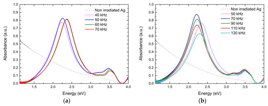
Figure 5.
Absorbance spectra for areas of two 12.5 nm Ag films, Ag #2 (a) and Ag #3 (b), irradiated with various laser frequency values.
For a silver film of similar thickness (Figure 5b), the effect of the frequency on the plasmonic characteristics was further investigated. Once again, minor third peaks around 3.25 eV were evident. Regarding the LPSR position, the main resonances were located at higher energy values for the extreme frequencies (50 and 130 kHz), while for the intermediate frequencies, they were nearly identical at around 2.21 eV. Likewise, the secondary peaks followed this behavior, but with smaller fluctuations in their values. Concerning the LSPR amplitude, for the main peaks, the rising frequency initially increased it, reaching a maximum at 70 kHz. However, the further increase in the frequency resulted in a continuously declining LSPR amplitude. The secondary peaks did not show a clear frequency dependence.
Figure 6 shows the absorption spectra of a 6 nm Ag film with various laser frequencies. Once again, two resonance peaks were observed for all cases, but in different positions compared to the thicker films studied above. It must also be noted that around 1.75 eV, a broad curve could be detected, similar to the third peaks identified in the previous Ag films.
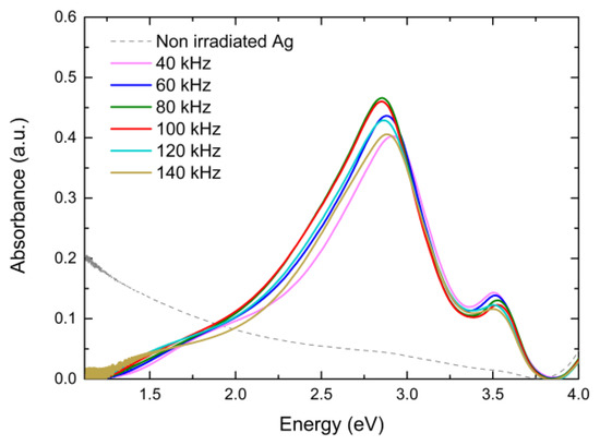
Figure 6.
Absorbance spectra for areas of a 6 nm Ag film, Ag #4, irradiated with various laser frequency values.
As for the LSPR position, the main LSPRs for the intermediate frequency values (80–120 kHz) were located around 2.85 eV. For the two lower frequencies (40, 60 kHz), the LSPR could be found around 2.9 eV, while the highest frequency (140 kHz) promoted a slight red shift. Furthermore, the increase in the laser frequency initially enhanced the main LSPR amplitude, reaching its maximum at 80 kHz. However, thereafter, a continuous decrease was observed. The secondary resonance peak showed an inversely related dependence on the laser frequency, as revealed by the declining amplitude.
Figure 7a–f graphically display the influence of the laser frequency on the LSPR characteristics for every examined film, and Table 3 provides detailed data thereof.
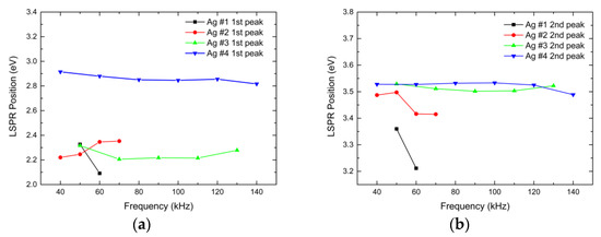
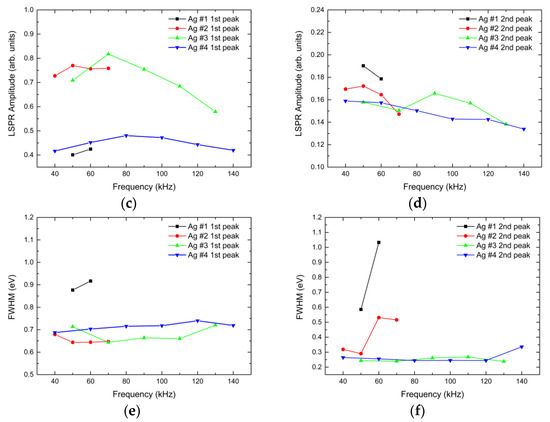
Figure 7.
Graphic illustrations of the LSPR characteristics for all Ag films treated with various laser frequency settings: Ag #1 (13.5 nm), Ag #2 and Ag #3 (12.5 nm), and Ag #4 (6 nm). (a,c,e) Data for the main (first) peaks; (b,d,f) data for the secondary peaks. The LSPR position is shown in (a,b), while the LSPR amplitude and FWHM are depicted in (c,d) and (e,f), respectively.

Table 3.
LSPR characteristics as a function of the frequency. The fill spacing for Ag#1 was 0.05 mm, while for the rest of the films, it was 0.0125 mm.
3.1.2. AgPd Multilayers
The UV–Vis absorbance spectra plotted in Figure 8a,b concern two AgPd multilayers with thicknesses of 7.5 nm and 12.3 nm, respectively, whose compositions are illustrated in the insets. Detailed data of the comparison between thermal and laser annealing of the AgPd multilayers are presented in the table below. No graphic illustrations are presented for these specimens since there are little data available. Both annealing methods resulted in single-peak LSPRs and delivered self-assembled AgPd nanoparticles, as shown in the AFM images. As expected, the LSPRs in this case were broader compared to those of the Ag nanoparticles due to the presence of Pd.
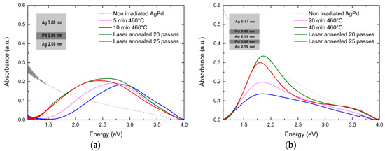
Figure 8.
Absorbance spectra of two AgPd multilayers with thicknesses of 7.5 nm (AgPd #1) (a) and (b) 12.3 nm (AgPd #2). Their compositions are shown in the insets. These multilayers were thermally annealed at 460 °C in a furnace in air and laser-annealed for 20 and 25 passes. Detailed data are shown in Table 4.
Thermal annealing was realized in a furnace in air at 460 °C for 5, 10, 20, and 40 min depending on the multilayer thickness. For the thinner multilayer (AgPd #1), laser annealing for 20 and 25 laser passes was able to introduce similar or even better LSPRs in terms of intensity and absorption peak width compared to thermal annealing. The LSPR positions of the laser-annealed areas were found at lower energy values, and their amplitude was slightly higher compared to that of the thermally annealed areas.
However, regarding the thicker multilayer, as clearly depicted in Figure 8b, laser annealing resulted in remarkably narrower and more intense LSPRs. The plasmonic resonance intensity was notably higher for the laser-annealed areas, while the LSPR position was found to be almost the same for all cases, as shown in Table 4.

Table 4.
LSPR characteristics of AgPd multilayers as a function of the laser passes and annealing time at 460 °C.
This plasmonic behavior is quite impressive since, along with the aforementioned results of the Ag films, it is verified that the nanosecond fiber laser used can produce qualitative plasmonic nanomaterials while providing manufacturing speed, practicality, scalability, and cost effectiveness. Additionally, considering that Pd is susceptible to oxidation when annealed in air at temperatures needed to obtain self-assembled nanoparticles [52], laser annealing did not induce any obvious signs of oxidation. On the contrary, it introduced noteworthy LSPRs, indicating that this nanostructuring method could be useful for various plasmonic materials and alloys or multilayers thereof.
3.2. Microstructure Analysis
In this section, we present selected AFM images that depict the surface morphology of the thermally and laser-annealed areas, as well as their nanoparticle size distributions.
3.2.1. Ag Ultrathin Films
Figure 9a,c,e show 2D and 3D AFM images and the nanoparticle size distribution diagram for the 13.5 nm Ag film (Ag #1), depicting the laser-annealed area with a fill spacing of 0.05 mm. The distribution of distinct particles, agglomerates, filament-like structures, and droplets can be observed, indicating that the fluence induced into this area was not sufficient to cause complete nanostructuring. Further analysis of this phenomenon is beyond the scope of this paper and will not be discussed. Figure 9b depicts the surface microstructure for an area of the same film, laser-annealed with a 0.0125 mm fill spacing. This area shows the largest LSPR amplitude in Figure 2, probably due to its dense nanoparticle distribution. In this case, more distinct and well-defined nanoparticles are present, as most of the filament-like structures formed distinct nanoparticles. However, the presence of some filament-like arrangements is still noticeable. The distribution diagrams reveal that the mean particle diameter is larger for the 0.0125 mm fill spacing, while the presence of a greater amount of agglomerates for 0.05 mm is evident as well.
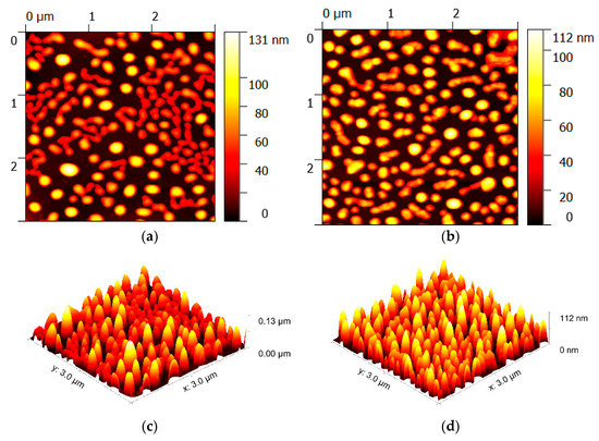
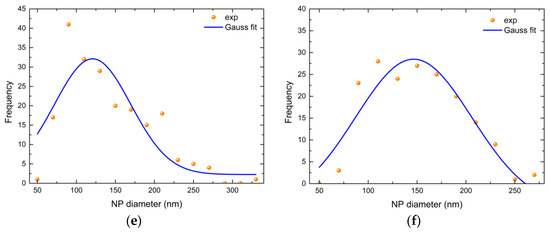
Figure 9.
Two- and three-dimensional AFM images and nanoparticle size distribution diagrams for two areas of a 13.5 nm Ag film (Ag #1): (a,c,e) the laser-annealed area with a fill spacing of 0.05 mm; (b,d,f) the area irradiated with a 0.0125 mm fill spacing.
Figure 10 corresponds to the same 13.5 nm Ag film (Ag #1) but illustrates an AFM image of the area irradiated with a frequency of 50 kHz and a 0.05 mm fill spacing. In contrast to Figure 9a, which shows the morphology of the area irradiated with the same fill spacing (0.05 mm) but a different frequency (60 kHz), one can see a bimodal distribution of scattered nanoparticles without any agglomerates. This indicates that complete nanostructuring took place under those laser settings. The lower frequency seems to have induced thermal energy deeper in the sample, leading to a bimodal distribution of both larger and smaller scattered nanoparticles.

Figure 10.
(a) Two- and (b) three-dimensional AFM images and nanoparticle size distribution diagram (c) for the area of the Ag #1 (13.5 nm) film irradiated at a frequency of 50 kHz with a 0.05 mm fill spacing.
Figure 11 and Figure 12 illustrate AFM images of the areas that displayed the largest LSPR amplitudes in the UV–Vis spectra (Figure 5a,b and Figure 6) across the variation in the laser frequency. Figure 11a shows an AFM image for the area of the first 12.5 nm Ag film (Ag #2) that was irradiated with a frequency of 50 kHz. A narrow distribution of large nanoparticles can be observed. Silver nanoparticles are densely scattered and, in some cases, they form aggregates. Some nanoparticles even exceed 300 nm in diameter. The combination of a small fill spacing value with a low laser frequency resulted in a wider energy distribution in the film, resulting in a narrow and dense distribution of large nanoparticles. The filament-like formations seen in the previous cases are not present, as they may have transformed into distinct nanoparticles packed closely to each other. This is probably due to the deeper heating caused by the lower laser frequency. However, in contrast to Figure 10, in this case, a single distribution is observed. The biggest overlap due to the smallest fill spacing may have led to a more uniform annealing, justifying the difference in the nanoparticle distributions.
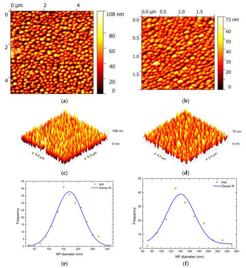
Figure 11.
Two- and three-dimensional AFM images and nanoparticle size distribution diagrams for the areas of the 12.5 nm Ag films (Ag #2 and Ag #3), which showed the greatest LSPR intensity. (a,c,e) The area of Ag #2 that was laser-annealed with a laser frequency of 50 kHz; (b,d,f) the area of Ag #3 irradiated with a laser frequency of 50 kHz.

Figure 12.
(a) Two- and (b) three-dimensional AFM images and nanoparticle size distribution diagram (c) for the area of the Ag #4 (6 nm) film irradiated at a frequency of 80 kHz.
Figure 11b shows the area of the second 12.5 nm film (Ag #3) with the largest LPSR amplitude irradiated with a frequency of 70 kHz. In this case, a very dense distribution of nanoparticles with minimal spacing between them is observed. Their average diameter and height are smaller than those of the previous specimen.
Regarding the thinner film Ag #4 (6 nm), Figure 12 depicts the area irradiated with a frequency of 80 kHz, resulting in a very dense but wider distribution of nanoparticles with a smaller diameter and height, compared to the thicker films. This is attributed to the lower initial thickness of the film. Additionally, the nanostructures of this film present an elongated, spherical shape, possibly due to the smaller agglomerated particles forming bigger ones.
The nanostructures obtained using this technique show excellent plasmonic behavior, with intense and narrow LSPRs. It is noteworthy that, even in this facile study, we were able to obtain plasmonic resonances of equivalent or even better quality compared to thermally annealed Ag films of similar thickness [14].
3.2.2. AgPd Multilayers
The following figures illustrate 2D and 3D AFM images and nanoparticle size distribution graphs of the thermally and laser-annealed AgPd multilayers.
Concerning the thinner AgPd #1 multilayer, Figure 13a shows its surface morphology after annealing at 460 °C for 5 min, and Figure 13b shows a laser-annealed area with 20 passes. The thermally annealed AgPd presents a distribution of mostly separated nanoparticles, while some agglomerates can also be observed. On the contrary, the laser-annealed area shows a very dense distribution of nanoparticles with a smaller average diameter, and some large nanoparticles (diameter > 150 nm) are present as well. The latter may have formed from smaller agglomerated particles.
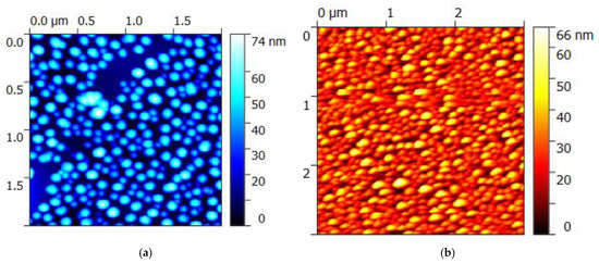
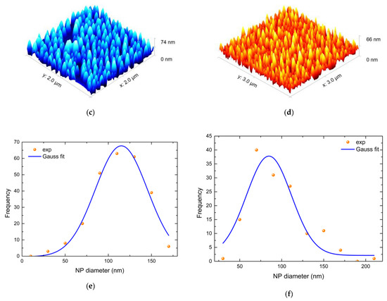
Figure 13.
Two- and three-dimensional AFM images and nanoparticle size distribution diagrams (a,c,e) for the area of the AgPd #1 (7.5 nm) multilayer that was thermally annealed at 460 °C for 5 min, and (b,d,f) for the area of the same multilayer that was laser-annealed with 20 passes.
Figure 14a shows the surface morphology of the 12.3 nm thick AgPd #2 multilayer thermally annealed at 460 °C for 5 min. Many small, agglomerated particles are visible, as well as a limited number of larger nanoparticles whose diameter exceeds 170 nm. Figure 14b depicts the surface morphology of the laser-annealed area with 20 passes of the same multilayer (AgPd #2). In this case, very large nanoparticles are observed along with some filament-like formations. The much larger average diameter of the nanoparticles might be responsible for the enhanced plasmonic resonance intensity in the laser annealing case.
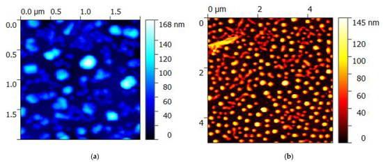
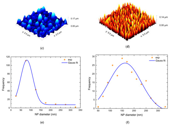
Figure 14.
Two- and three-dimensional AFM images and nanoparticle size distribution diagrams (a,c,e) for the area of the AgPd #2 (12.3 nm) multilayer that was thermally annealed at 460 °C for 20 min, and (b,d,f) for the area of the same multilayer that was laser-annealed with 20 passes. The multilayer was cut into two pieces so that both annealing methods could be carried out.
4. Discussion
The demand for rapid and cost-effective fabrication of tunable plasmonic nanostructures on a large scale has been a significant challenge in the field of plasmonics. In this study, we investigated the feasibility of an industrial-friendly laser technique that utilizes an ns fiber laser for efficient large-scale plasmonic nanostructuring.
Our approach provides a practical solution, exploiting fiber lasers’ strengths to create a simple, fast, cost-efficient, and scalable nanofabrication method. Notably, the use of fiber lasers for plasmonic nanostructuring has been explored to a very limited extent [38,39], making our study a valuable contribution to the field. Moreover, the proposed method involves laser thermal treatment under ambient conditions, which is a distinct advantage when industrial-scale manufacturing is in mind, eliminating the need for specialized equipment and complex sample preparation procedures.
Combining simplicity, speed, cost efficiency, and scalability with the strengths of the fiber laser used, our approach offers a viable alternative to established fabrication options, such as thermal [8,11,12,14,15,29,30,31] or laser annealing of metallic films with conventional laser sources (excimer, Nd:YAG, CO2, etc.) [9,13,16,17,18,19,20,21,28,32,33,34,35,36,37,40,41,42,43,44,45,46]. Overall, our findings demonstrate the potential of using fiber lasers for large-scale plasmonic nanostructuring and suggest new possibilities for the field.
Our method focuses on the direct growth of plasmonic nanostructures on the surface of metallic films, multilayers, or alloys on a large scale, but it could also be used for the embedding of metallic nanoparticles on dielectric matrixes [9,13,17,19,20] and the processing of other materials too.
The proposed laser technique’s ability to achieve tunable, intense, and narrow LSPRs is promising for fabricating functional plasmonic materials. These materials have the potential to find applications in a range of fields, including optoelectronics, photothermal therapy, sensing, surface-enhanced Raman spectroscopy (SERS), catalysis, diagnostic imaging, and energy harvesting [1,2,3,4,5,6,7,8,9,10,16,21,24,25,26,27,36,37,53]. Additionally, the proposed technique could be utilized after suitable adjustment in optothermoplasmonic nanolithography [54], optothermal tweezers, and laser printing for the fabrication of nanostructured materials for photonic and electronic devices [39,55,56,57,58].
By varying the laser parameters, namely, the fill spacing, frequency, and number of passes, we successfully fabricated self-assembled plasmonic nanoparticles of various diameters directly onto magnetron sputtered films and multilayers. As already mentioned, these nanostructures exhibited intense and narrow LSPRs, which are highly desirable for plasmonic-based applications.
In comparison with prior studies that investigated Ag films of similar thickness by means of thermal annealing [14], laser annealing [38], or a combination of both [18,21], the LSPR amplitude of the Ag films presented here was equivalent or even superior, depending on the laser settings. Additionally, we could consistently detect two LSPRs for all Ag films, while the existence of a third or even a fourth peak was evident several times in the Ag absorption curves. These secondary peaks could be the result of multiple scattering inside the films’ microstructure. In several cases, we obtained closely arranged nanostructures or aggregates of various shapes and sizes that could account for this phenomenon. Furthermore, the two observed LSPRs exhibited different plasmonic behaviors across the variation in the laser settings. A possible explanation for their different behaviors could be related to structural variations in the films at the microscopic level. The films are irradiated in different areas as the laser annealing settings change, and since magnetron sputtering deposition does not guarantee absolute uniformity over the entire film, minor structural variations may exist among different irradiated areas. Consequently, the laser beam interacts with a non-identical surface every time, resulting in minor differences in the geometry or interparticle distance of the self-assembled nanostructures. Since the first and second LSPRs are based on nanostructures with different geometries, the behavior of each peak may present differences with varying laser annealing settings. Additionally, Figure 3 and Figure 7 rely on data from Gaussian fittings after background subtraction, whose errors should be taken into consideration as well. The nanoparticle size was found to depend on the initial thickness of the specimen and laser annealing settings. The average nanoparticle diameter was around 150 nm for the highest LSPR amplitudes in the thicker Ag films (Ag #1–3), while for the thinner Ag #4, it was around 95 nm. This is to be expected due to the thicker initial film thickness. The large size of the grown nanoparticles accounts for the high absorbance values. Laser annealing seemed to be effective on every specimen processed; however, the thicker Ag films (Ag #1–3) were slightly more responsive (in terms of the LSPR amplitude) to the laser parameters’ variation than the thinner (Ag #4) film.
Regarding the AgPd multilayers, the LSPRs obtained through laser annealing were superior to those obtained through thermal annealing in the present study, as well as in [15], which utilized thermal annealing exclusively. As observed in the Ag films, the thicker (AgPd #2) multilayer exhibited superior LSPRs compared to AgPd #1. The thicker layer not only showed a higher amplitude—as expected due to its greater initial thickness—but also exhibited more pronounced LSPRs. Additionally, even though the AgPd multilayers were subjected to large amounts of thermal energy in air, no Pd oxidation signs were observed. Laser annealing is known to promote liquid-state dewetting, after achieving melting point temperatures [42]. As already mentioned in the results, Pd is susceptible to oxidation in this temperature range, and the presence of PdO could be detected by a small discontinuity in the absorbance spectra at 2.2 eV [15], but this is not the case here. The absence of oxidation could be attributed to two factors: firstly, the ultra-fast nanosecond annealing, which minimized the material’s exposure time to high temperatures, and secondly, the presence of a thick Ag top layer that may have provided additional protection to the internal Pd layers.
Additionally, the thinner samples of both cases studied (Ag #4 and AgPd #1) exhibited very dense nanoparticle distributions, as shown in Figure 12a and Figure 13b. This finding could be attributed to the lower temperature elevation on the film surface during laser annealing, due to heat diffusion into the substrate. According to [32], thinner films are expected to dissipate heat faster than thicker films. Therefore, the faster cooling rates of the thinner specimens might have promoted dense nanoparticle distributions.
Based on these results, it is clear that the proposed nanostructuring method can be valuable for a wide range of materials, even those which may be challenging to manipulate under ambient conditions. This creates new opportunities for potential mass manufacturing of novel materials with reduced costs and required production times.
In several cases, agglomerates or filament-like structures were observed. This highlights the importance of finely tuning the laser settings to achieve full control of the annealing process and nanostructuring in general. It should be emphasized that, in order to configure the optimal laser settings, one has to take into consideration the properties (thermal conductivity, melting point, etc.) of both the irradiated material and its substrate, as well as their interaction.
An improved laser configuration is expected to accelerate this technique even more and provide a wider tunability range and higher precision. All of the above, along with the compactness, operational benefits, and freedom of patterning that the fiber laser source provides, could potentially render this straightforward method a platform for large-scale plasmonic applications.
Future research should focus on fine-tuning the industrial laser source to achieve full control over the nanostructuring process and even exploit its capability to induce nanostructures that exhibit multiple LSPRs. This could lead to high-quality tunable plasmonic materials that can provide multiple selectivity for energy harvesting, sensing, or catalysis applications. Testing the performance of the fiber laser in various environments (e.g., under vacuum) is necessary, as the environment greatly affects the properties of the grown nanostructures [36]. Finally, more materials, as well as their oxidation behavior, could be studied.
5. Conclusions
In conclusion, this work demonstrated rapid and efficient plasmonic nanostructuring of metallic ultrathin films and multilayers with laser annealing at ambient conditions. Additionally, it was possible to tune their LSPR characteristics by only configuring the laser parameters, such as the fill spacing, laser frequency, and number of passes. The plasmonic behavior of the laser-annealed Ag ultrathin films and AgPd multilayers was remarkable, showing intense and narrow LSPRs whose characteristics depended on the initial film thickness and laser settings. Furthermore, Ag and AgPd nanoparticles of various diameters were obtained, and a comparison with thermal annealing was also carried out for the AgPd multilayers in order to emphasize the feasibility, versatility, and potential of this method.
The proposed method can deliver plasmonic nanostructures of satisfactory quality while simultaneously providing advantages in patterning design, scalability, and overall manufacturing practicality. The laser used in this study is an industrial nanosecond fiber laser source that is fully compatible with typical streamlined industrial processes. Therefore, this methodology paves the way towards efficient large-scale plasmonic nanostructuring with high-resolution patterning. Ultimately, further optimization of the laser parameters could improve this method in every aspect and expand its application to more plasmonic materials.
Author Contributions
Conceptualization, D.A. and D.N.; methodology, V.K.; validation, D.N., P.F. and V.K.; formal analysis, D.N.; investigation, D.N. and P.F.; resources, D.A., S.G. and P.P.; data curation, D.N.; writing—original draft preparation, D.N.; writing—review and editing, D.A., S.G. and P.P.; visualization, D.A.; supervision, D.A. and S.G.; project administration, D.A. and P.P. All authors have read and agreed to the published version of the manuscript.
Funding
This research received no external funding.
Institutional Review Board Statement
Not applicable.
Informed Consent Statement
Not applicable.
Data Availability Statement
Not applicable.
Conflicts of Interest
The authors declare no conflict of interest.
References
- Hutter, E.; Fendler, J.H. Exploitation of Localized Surface Plasmon Resonance. Adv. Mater. 2004, 16, 1685–1706. [Google Scholar] [CrossRef]
- Homola, J. Surface Plasmon Resonance Sensors for Detection of Chemical and Biological Species. Chem. Rev. 2008, 108, 462–493. [Google Scholar] [CrossRef]
- Haes, A.J.; Hall, W.P.; Chang, L.; Klein, W.L.; Van Duyne, R.P. A Localized Surface Plasmon Resonance Biosensor: First Steps toward an Assay for Alzheimer’s Disease. Nano Lett. 2004, 4, 1029–1034. [Google Scholar] [CrossRef]
- Lagos, N.; Sigalas, M.M.; Lidorikis, E. Theory of Plasmonic Near-Field Enhanced Absorption in Solar Cells. Appl. Phys. Lett. 2011, 99, 063304. [Google Scholar] [CrossRef]
- Fei Guo, C.; Sun, T.; Cao, F.; Liu, Q.; Ren, Z. Metallic Nanostructures for Light Trapping in Energy-Harvesting Devices. Light Sci. Appl. 2014, 3, e161. [Google Scholar] [CrossRef]
- Zeng, S.; Baillargeat, D.; Ho, H.-P.; Yong, K.-T. Nanomaterials Enhanced Surface Plasmon Resonance for Biological and Chemical Sensing Applications. Chem. Soc. Rev. 2014, 43, 3426. [Google Scholar] [CrossRef]
- Austin, L.A.; Mackey, M.A.; Dreaden, E.C.; El-Sayed, M.A. The Optical, Photothermal, and Facile Surface Chemical Properties of Gold and Silver Nanoparticles in Biodiagnostics, Therapy, and Drug Delivery. Arch. Toxicol. 2014, 88, 1391–1417. [Google Scholar] [CrossRef]
- Grammatikopoulos, S.; Pappas, S.; Dracopoulos, V.; Poulopoulos, P.; Fumagalli, P.; Velgakis, M.; Politis, C. Self-Assembled Au Nanoparticles on Heated Corning Glass by Dc Magnetron Sputtering: Size-Dependent Surface Plasmon Resonance Tuning. J. Nanopart. Res. 2013, 15, 1446. [Google Scholar] [CrossRef]
- Kalfagiannis, N.; Koutsogeorgis, D.C.; Lidorikis, E.; Patsalas, P. Laser Annealing as a Platform for Plasmonic Nanostructuring. In Nanoplasmonics-Fundamentals and Applications; Barbillon, G., Ed.; InTech: London, UK, 2017; ISBN 978-953-51-3277-6. [Google Scholar]
- Mayer, K.M.; Hafner, J.H. Localized Surface Plasmon Resonance Sensors. Chem. Rev. 2011, 111, 3828–3857. [Google Scholar] [CrossRef]
- Stamatelatos, A.; Sousanis, A.; Chronis, A.G.; Sigalas, M.M.; Grammatikopoulos, S.; Poulopoulos, P. Analysis of Localized Surface Plasmon Resonances in Gold Nanoparticles Surrounded by Copper Oxides. J. Appl. Phys. 2018, 123, 083103. [Google Scholar] [CrossRef]
- Hirai, M.; Kumar, A. Wavelength Tuning of Surface Plasmon Resonance by Annealing Silver-Copper Nanoparticles. J. Appl. Phys. 2006, 100, 014309. [Google Scholar] [CrossRef]
- Doster, J.; Baraldi, G.; Gonzalo, J.; Solis, J.; Hernandez-Rueda, J.; Siegel, J. Tailoring the Surface Plasmon Resonance of Embedded Silver Nanoparticles by Combining Nano- and Femtosecond Laser Pulses. Appl. Phys. Lett. 2014, 104, 153106. [Google Scholar] [CrossRef]
- Chronis, A.G.; Stamatelatos, A.; Grammatikopoulos, S.; Sigalas, M.M.; Karoutsos, V.; Maratos, D.M.; Lysandrou, S.P.; Trachylis, D.; Politis, C.; Poulopoulos, P. Microstructure and Plasmonic Behavior of Self-Assembled Silver Nanoparticles and Nanorings. J. Appl. Phys. 2019, 125, 023106. [Google Scholar] [CrossRef]
- Ntemogiannis, D.; Tsarmpopoulou, M.; Chronis, A.G.; Anyfantis, D.I.; Barnasas, A.; Grammatikopoulos, S.; Sigalas, M.; Poulopoulos, P. On the Localized Surface Plasmonic Resonances of AgPd Alloy Nanoparticles by Experiment and Theory. Coatings 2021, 11, 893. [Google Scholar] [CrossRef]
- Arnob, M.M.P.; Zhao, F.; Zeng, J.; Santos, G.M.; Li, M.; Shih, W.-C. Laser Rapid Thermal Annealing Enables Tunable Plasmonics in Nanoporous Gold Nanoparticles. Nanoscale 2014, 6, 12470–12475. [Google Scholar] [CrossRef]
- Koleva, M.E.; Nedyalkov, N.N.; Karashanova, D.; Atanasova, G.B.; Stepanov, A.L. Modification of Plasmon Resonance Properties of Noble Metal Nanoparticles inside the Glass Matrices. Appl. Surf. Sci. 2019, 475, 974–981. [Google Scholar] [CrossRef]
- Oh, H.; Pyatenko, A.; Lee, M. A Hybrid Dewetting Approach to Generate Highly Sensitive Plasmonic Silver Nanoparticles with a Narrow Size Distribution. Appl. Surf. Sci. 2021, 542, 148613. [Google Scholar] [CrossRef]
- Bazioti, C.; Dimitrakopulos, G.P.; Kehagias, T.; Komninou, P.; Siozios, A.; Lidorikis, E.; Koutsogeorgis, D.C.; Patsalas, P. Influence of Laser Annealing on the Structural Properties of Sputtered AlN:Ag Plasmonic Nanocomposites. J. Mater. Sci. 2014, 49, 3996–4006. [Google Scholar] [CrossRef]
- Bellas, D.V.; Toliopoulos, D.; Kalfagiannis, N.; Siozios, A.; Nikolaou, P.; Kelires, P.C.; Koutsogeorgis, D.C.; Patsalas, P.; Lidorikis, E. Simulating the Opto-Thermal Processes Involved in Laser Induced Self-Assembly of Surface and Sub-Surface Plasmonic Nano-Structuring. Thin Solid Film. 2017, 630, 7–24. [Google Scholar] [CrossRef]
- Hong, R.; Shao, W.; Sun, W.; Deng, C.; Tao, C.; Zhang, D. Laser Irradiation Induced Tunable Localized Surface Plasmon Resonance of Silver Thin Film. Opt. Mater. 2018, 77, 198–203. [Google Scholar] [CrossRef]
- West, P.R.; Ishii, S.; Naik, G.V.; Emani, N.K.; Shalaev, V.M.; Boltasseva, A. Searching for Better Plasmonic Materials. Laser Photon. Rev. 2010, 4, 795–808. [Google Scholar] [CrossRef]
- Huang, X.; Tang, S.; Mu, X.; Dai, Y.; Chen, G.; Zhou, Z.; Ruan, F.; Yang, Z.; Zheng, N. Freestanding Palladium Nanosheets with Plasmonic and Catalytic Properties. Nat. Nanotech 2011, 6, 28–32. [Google Scholar] [CrossRef]
- Kumar-Krishnan, S.; Estevez-González, M.; Pérez, R.; Esparza, R.; Meyyappan, M. A General Seed-Mediated Approach to the Synthesis of AgM (M = Au, Pt, and Pd) Core–Shell Nanoplates and Their SERS Properties. RSC Adv. 2017, 7, 27170–27176. [Google Scholar] [CrossRef]
- Salem, M.A.; Bakr, E.A.; El-Attar, H.G. Pt@Ag and Pd@Ag Core/Shell Nanoparticles for Catalytic Degradation of Congo Red in Aqueous Solution. Spectrochim. Acta Part A Mol. Biomol. Spectrosc. 2018, 188, 155–163. [Google Scholar] [CrossRef]
- Sui, M.; Kunwar, S.; Pandey, P.; Lee, J. Strongly Confined Localized Surface Plasmon Resonance (LSPR) Bands of Pt, AgPt, AgAuPt Nanoparticles. Sci. Rep. 2019, 9, 16582. [Google Scholar] [CrossRef]
- Nazemi, M.; Soule, L.; Liu, M.; El-Sayed, M.A. Ambient Ammonia Electrosynthesis from Nitrogen and Water by Incorporating Palladium in Bimetallic Gold–Silver Nanocages. J. Electrochem. Soc. 2020, 167, 054511. [Google Scholar] [CrossRef]
- Ooms, M.D.; Jeyaram, Y.; Sinton, D. Disposable Plasmonics: Rapid and Inexpensive Large Area Patterning of Plasmonic Structures with CO2 Laser Annealing. Langmuir 2015, 31, 5252–5258. [Google Scholar] [CrossRef]
- Grammatikopoulos, S.; Stamatelatos, A.; Delimitis, A.; Sousanis, A.; Chrisanthopoulou, A.; Trachylis, D.; Politis, C.; Poulopoulos, P. Growth of Au Nanoparticles in NiO via Short Annealing of Precursor Material Thin Film and Optimization of Plasmonics. Phys. Status Solidi A 2017, 214, 1700303. [Google Scholar] [CrossRef]
- Sousanis, A.; Grammatikopoulos, S.; Delimitis, A.; Dracopoulos, V.; Poulopoulos, P. Localized Surface Plasmon Resonances after Selective Oxidization of AuCu Solid Solution Nanocrystalline Films. Appl. Phys. Lett. 2015, 107, 011903. [Google Scholar] [CrossRef]
- Sousanis, A.; Poulopoulos, P.; Karoutsos, V.; Trachylis, D.; Politis, C. Giant Enhancement of Small Photoluminescent Signals on Glass Surfaces Covered by Self-Assembled Silver Nanorings. J. Nanosci. Nanotechnol. 2017, 17, 1428–1433. [Google Scholar] [CrossRef]
- Henley, S.J.; Carey, J.D.; Silva, S.R.P. Pulsed-Laser-Induced Nanoscale Island Formation in Thin Metal-on-Oxide Films. Phys. Rev. B 2005, 72, 195408. [Google Scholar] [CrossRef]
- Kalfagiannis, N.; Siozios, A.; Bellas, D.V.; Toliopoulos, D.; Bowen, L.; Pliatsikas, N.; Cranton, W.M.; Kosmidis, C.; Koutsogeorgis, D.C.; Lidorikis, E.; et al. Selective Modification of Nanoparticle Arrays by Laser-Induced Self Assembly (MONA-LISA): Putting Control into Bottom-up Plasmonic Nanostructuring. Nanoscale 2016, 8, 8236–8244. [Google Scholar] [CrossRef]
- Thair, S.S.; Rasheed, B.G.; Al-Hamaoy, A.R. Effect of Laser Annealing on Gold Nanofilm. Mater. Today Proc. 2021, 42, 2984–2989. [Google Scholar] [CrossRef]
- Maurya, S.K.; Uto, Y.; Kashihara, K.; Yonekura, N.; Nakajima, T. Rapid Formation of Nanostructures in Au Films Using a CO2 Laser. Appl. Surf. Sci. 2018, 427, 961–965. [Google Scholar] [CrossRef]
- Nikov, R.G.; Nedyalkov, N.N.; Atanasov, P.A.; Hirsch, D.; Rauschenbach, B.; Grochowska, K.; Sliwinski, G. Characterization of Ag Nanostructures Fabricated by Laser-Induced Dewetting of Thin Films. Appl. Surf. Sci. 2016, 374, 36–41. [Google Scholar] [CrossRef]
- Henley, S.J.; Carey, J.D.; Silva, S.R.P. Laser-Nanostructured Ag Films as Substrates for Surface-Enhanced Raman Spectroscopy. Appl. Phys. Lett. 2006, 88, 081904. [Google Scholar] [CrossRef]
- Hong, R.; Sun, W.; Liu, Q.; Li, Z.; Tao, C.; Zhang, D.; Zhang, D. Al-Induced Tunable Surface Plasmon Resonance of Ag Thin Film by Laser Irradiation. Appl. Phys. Express 2019, 12, 085503. [Google Scholar] [CrossRef]
- Kuroiwa, Y.; Tatsuma, T. Laser Printing of Translucent Plasmonic Full-Color Images with Transmission-Scattering Dichroism of Silver Nanoparticles. ACS Appl. Nano Mater. 2020, 3, 2472–2479. [Google Scholar] [CrossRef]
- Favazza, C.; Kalyanaraman, R.; Sureshkumar, R. Robust Nanopatterning by Laser-Induced Dewetting of Metal Nanofilms. Nanotechnology 2006, 17, 4229–4234. [Google Scholar] [CrossRef]
- Trice, J.; Thomas, D.; Favazza, C.; Sureshkumar, R.; Kalyanaraman, R. Pulsed-Laser-Induced Dewetting in Nanoscopic Metal Films: Theory and Experiments. Phys. Rev. B 2007, 75, 235439. [Google Scholar] [CrossRef]
- Krishna, H.; Shirato, N.; Favazza, C.; Kalyanaraman, R. Pulsed Laser Induced Self-Organization by Dewetting of Metallic Films. J. Mater. Res. 2011, 26, 154–169. [Google Scholar] [CrossRef]
- Yadavali, S.; Khenner, M.; Kalyanaraman, R. Pulsed Laser Dewetting of Au Films: Experiments and Modeling of Nanoscale Behavior. J. Mater. Res. 2013, 28, 1715–1723. [Google Scholar] [CrossRef]
- Oh, Y.; Lee, M. Single-Pulse Transformation of Ag Thin Film into Nanoparticles via Laser-Induced Dewetting. Appl. Surf. Sci. 2017, 399, 555–564. [Google Scholar] [CrossRef]
- Oh, H.; Pyatenko, A.; Lee, M. Laser Dewetting Behaviors of Ag and Au Thin Films on Glass and Si Substrates: Experiments and Theoretical Considerations. Appl. Surf. Sci. 2019, 475, 740–747. [Google Scholar] [CrossRef]
- Resta, V.; Siegel, J.; Bonse, J.; Gonzalo, J.; Afonso, C.N.; Piscopiello, E.; Van Tenedeloo, G. Sharpening the Shape Distribution of Gold Nanoparticles by Laser Irradiation. J. Appl. Phys. 2006, 100, 084311. [Google Scholar] [CrossRef]
- Kannatey-Asibu, E. Principles of Laser Materials Processing; John Wiley & Sons, Inc.: Hoboken, NJ, USA, 2009; ISBN 978-0-470-45930-0. [Google Scholar]
- Gabzdyl, J. Fibre Lasers Make Their Mark. Nat. Photon 2008, 2, 21–23. [Google Scholar] [CrossRef]
- Mary, R.; Choudhury, D.; Kar, A.K. Applications of Fiber Lasers for the Development of Compact Photonic Devices. IEEE J. Select. Top. Quantum Electron. 2014, 20, 72–84. [Google Scholar] [CrossRef]
- Poddar, R.; Sahu, A.K.; Jha, S. Experimental Investigation of Nano Second Fiber Laser Micro Grooving on Cylindrical Surface. Mater. Today Proc. 2021, 44, 2005–2012. [Google Scholar] [CrossRef]
- Khorasani, M.; Ghasemi, A.; Leary, M.; Sharabian, E.; Cordova, L.; Gibson, I.; Downing, D.; Bateman, S.; Brandt, M.; Rolfe, B. The Effect of Absorption Ratio on Meltpool Features in Laser-Based Powder Bed Fusion of IN718. Opt. Laser Technol. 2022, 153, 108263. [Google Scholar] [CrossRef]
- Samoylov, A.M.; Ivkov, S.A.; Pelipenko, D.I.; Sharov, M.K.; Tsyganova, V.O.; Agapov, B.L.; Tutov, E.A.; Badica, P. Structural Changes in Palladium Nanofilms during Thermal Oxidation. Inorg. Mater. 2020, 56, 1020–1026. [Google Scholar] [CrossRef]
- Qian, C.; Guo, Q.; Xu, M.; Yuan, Y.; Yao, J. Improving the SERS Detection Sensitivity of Aromatic Molecules by a PDMS-Coated Au Nanoparticle Monolayer Film. RSC Adv. 2015, 5, 53306–53312. [Google Scholar] [CrossRef]
- Lin, L.; Li, J.; Li, W.; Yogeesh, M.N.; Shi, J.; Peng, X.; Liu, Y.; Rajeeva, B.B.; Becker, M.F.; Liu, Y.; et al. Optothermoplasmonic Nanolithography for On-Demand Patterning of 2D Materials. Adv. Funct. Mater. 2018, 28, 1803990. [Google Scholar] [CrossRef]
- Li, J.; Hill, E.H.; Lin, L.; Zheng, Y. Optical Nanoprinting of Colloidal Particles and Functional Structures. ACS Nano 2019, 13, 3783–3795. [Google Scholar] [CrossRef] [PubMed]
- Li, J.; Zheng, Y. Optothermally Assembled Nanostructures. Acc. Mater. Res. 2021, 2, 352–363. [Google Scholar] [CrossRef]
- Peng, X.; Li, J.; Lin, L.; Liu, Y.; Zheng, Y. Opto-Thermophoretic Manipulation and Construction of Colloidal Superstructures in Photocurable Hydrogels. ACS Appl. Nano Mater. 2018, 1, 3998–4004. [Google Scholar] [CrossRef]
- Roberts, A.S.; Novikov, S.M.; Yang, Y.; Chen, Y.; Boroviks, S.; Beermann, J.; Mortensen, N.A.; Bozhevolnyi, S.I. Laser Writing of Bright Colors on Near-Percolation Plasmonic Reflector Arrays. ACS Nano 2019, 13, 71–77. [Google Scholar] [CrossRef]
Disclaimer/Publisher’s Note: The statements, opinions and data contained in all publications are solely those of the individual author(s) and contributor(s) and not of MDPI and/or the editor(s). MDPI and/or the editor(s) disclaim responsibility for any injury to people or property resulting from any ideas, methods, instructions or products referred to in the content. |
© 2023 by the authors. Licensee MDPI, Basel, Switzerland. This article is an open access article distributed under the terms and conditions of the Creative Commons Attribution (CC BY) license (https://creativecommons.org/licenses/by/4.0/).