Communication

Topology Optimization of Low-Loss Z-Bend 2D Photonic Crystal Waveguide

1
Beijing Key Laboratory of Space-Ground Interconnection and Convergence, Beijing University of Posts and Telecommunications, Beijing 100876, China
2
School of Electronic Engineering, Beijing University of Posts and Telecommunications, Beijing 100876, China
3
State Key Laboratory of Information Photonics and Optical Communications, Beijing University of Posts and Telecommunications, Beijing 100876, China
4
Southwest Institute of Technical Physics, Renminnan Road 4-7, Chengdu 610041, China
*
Author to whom correspondence should be addressed.
Photonics 2023, 10(2), 202; https://doi.org/10.3390/photonics10020202
Submission received: 23 November 2022 / Revised: 28 December 2022 / Accepted: 28 January 2023 / Published: 13 February 2023
(This article belongs to the Section Quantum Photonics and Technologies)

Abstract

:
In this article, we design a low-loss, high-bandwidth Z-bend photonic silicon crystal waveguide bending in a triangular lattice through topology optimization. Based on the topological optimization method, we change the relative position of air holes in the global scope to maximize the transmittance and bandwidth of the waveguide. The simulation results indicate that the transmission characteristics can be effectively improved with our method. After the optimization, the loss of the waveguide can be reduced to −5 dB and the bandwidth can increase to 160 nm. Our research has great significance for further optimizing the propagation of light in photonic crystals.

1. Introduction

Photonic crystal (PhC) is an artificial structure composed of a periodic arrangement of materials with varying refractive indexes. Bragg scattering will occur at the dielectric interface when there is a substantial refractive index difference between the two materials [1,2]. This prevents certain frequencies of light from passing through. This phenomenon is known as the photonic band gap (PBG) [3,4,5,6,7,8]. Because of the PBG, photonics have a wide range of applications in beam splitters [9,10], filters [11,12,13,14], resonators [15,16,17] and integrated circuits [18]. When a line defect or point defect mode is introduced into a PhC, its periodic structure is broken, and the propagation of light waves is well limited or enhanced [19]. Based on this feature, photonic crystal waveguides (PCW) can be designed with low loss and high transmission efficiency which is applied to many kinds of photoelectronic devices [10,20,21,22,23].
In two-dimensional photonic crystal devices, changing the direction of light propagation is unavoidable. Therefore, the curved PCW are more and more widely studied [24,25,26,27]. As a typical structure in two-dimensional photonic crystal, a series of studies were carried out on Z-curved PCW because their two continuous 120° bends can be applied to various photonic crystal devices. For curved PhC, the transmission loss originates from the discontinuous periodic structure at the bend. Hence, the research of curved waveguides with low loss and a high-bandwidth performance has attracted significant interest [24,25]. Due to the mismatching of the guide modes between the straight waveguide and the curved waveguide [28], various research was carried out to reduce the loss at the curved waveguide through resonance matching [29], topology optimization [30,31] or impedance matching [32,33]. Recently, P.I. Bole et al. designed Z-bending PCW under the TE mode with a bending loss of 3 dB and a bandwidth of 200 nm [26]. The shape of the air holes was changed by using ion beam etching at the local bend. Zhao Q et al. studied the effect of the groove structure on a 120° W1 PCW elbow [24]. The simulation results showed that the arc-slotted PCW bend has a 3 dB bending loss and a 150 nm bandwidth. In these previous methods, the independent influence on the position of each hole is difficult to calculate because it requires a large parameter space which makes the calculation too large.
In this paper, the relative position of each air hole is changed independently on a global basis by the topology optimization to achieve high transmission structure design without the need of massive computing resources. Moreover, this method is suitable for any shape of air holes and any structure of PCW. In this paper, we use the finite element method to calculate the properties of PhCs based on Maxwell’s equations [34]. A two-dimensional triangular structure arrangement PhC model with line defects is designed [35,36]. The light scattering and reflection is simulated by a scattering boundary condition. Then, the topology optimization adopts the gradient optimization method to find the optimal solution suitable for this structure through an iterative calculation in the independent hole position parameter space.
Based on these methods, we studied two kinds of Z-bending waveguides on the Silicon-On-Insulator (SOI) platform: one is a straight Z waveguide and the other is a curved Z waveguide which has different structures in its bending part. The simulation results show that both traditional Z-bending waveguide structures have large transmission losses. The transmission characteristics of a curved Z waveguide are obviously improved compared to that of a straight Z waveguide. For the straight Z waveguide, the maximum loss is about −48 dB. For the curved Z waveguide, the maximum loss is approximately −34 dB. However, through our topology optimization method, the transmission loss of both kinds of Z waveguides can be significantly reduced. Both structures have about a −5 dB loss and 160 nm bandwidth, from 1440 nm to 1600 nm. The moving distance of air holes with a relative displacement greater than 25 nm near the curved waveguide are described by the topology optimization. Finally, the universality of the topology optimization method is verified by studying the different sizes of 90° curved waveguides and triangular lattice curved waveguides. Our method will benefit the highly efficient application of the PCW in photonic crystal optical equipment.

2. Model of Z Waveguide Bends

In the study, we studied two forms of Z waveguides. They are constructed of homogeneous medium and triangular lattice air holes, as illustrated in Figure 1. Straight waveguides are connected to curved waveguides on both sides. The model has periodic media in the x y -plane, but the bending part presents an aperiodic arrangement. The medium is uniform on the z axis. The radius of the air hole a = 251 nm, lattice constant l   =   2.82     a . The PhC is composed of silicon (n = 3.48) background and air holes. Triangular planar PhCs formed by high refractive index materials such as silicon and gallium arsenide have large PBG, which can limit and control the propagation of light with specific frequency. The difference between the two forms of PhCs is that the position of the two dark blue air holes is modified. In order to simulate in a limited space, we must set the boundary conditions of the system. Here, we set the scattering boundary condition at the boundary of the simulation to indicate that the light on the boundary is completely scattered. Then, we can calculate the scattering (S) parameters of the waveguide to characterize the transmittance, reflectivity and absorption rate of the system.
We assume that all the materials in the system are all linear materials. At this time, Maxwell’s equations for a specific frequency can be transformed into the following propagation equations:
× ( μ r 1 × E ) ω 2 c 0 2 ( ϵ r i σ ω ϵ 0 ) E = 0
where μ r represents relative permeability; ϵ r stands for relative permittivity; σ stands for electrical conductivity; c 0 is the speed of light in air; E is the strength of the field; ω is the angular frequency.
In order to calculate the reflection coefficient of the input port and the transmission coefficient of the output port, S parameter is introduced here for calculation. S 11 is the reflection coefficient of the input port when the output port of the tested component is connected to a matching load. S 21 is the transmission coefficient from port 1 to port 2 of the device when the output port of the tested component is connected to a matching load. The specific transmission coefficient and reflection coefficient have the forms as follows:
S 11 = ( E E 1 ) × E 1 d Ω E 1 × E 1 d Ω
S 21 = E × E 2 d Ω E 2 × E 2 d Ω
T ( ω ) = | S 21 | 2
R ( ω ) = | S 11 | 2
where Ω is the geometry of the entire model; E is the intensity of the electric field during transmission in the PhC; E 1 is the electric field intensity of the incident light; E 2 is the electric field intensity of the outgoing light.
The MMA method approximates the objective function and constraint function as some convex sequence subproblems by mathematical programming. Solving the optimization problem based on Lagrange duality method. Then, the gradient method is used to obtain the optimal design variables of the subproblems. For the general optimization problem, it can be expressed as
m i n : f 0 ( X ) f i ( X ) 0 x j m i n x j x j m a x ( j = 1 , 2 , , n ; i = 1 , 2 , , m )
where i = 1, 2, …, m is the number of constraints; j = 1, 2, …, n is the number of design variables. For large and complex structural optimization problems, MMA algorithm can speed up convergence and calculation. In the k iteration, the optimization problems are approximated by MMA
m i n : f ˜ 0 ( x ( k ) ) f ˜ 0 ( x ( k ) ) 0 α j k x β j k ( j = 1 , 2 , , n ; i = 1 , 2 , , m )
where i = 1, 2, …, m is the number of constraints; j = 1, 2, …, n is the number of design variables; α j k and β j k are move limits; f ˜ ( x ( k ) ) is the first approximation of f i to the k iteration point.
In order to apply the topology optimization method to the transmission characteristics of light in photonic crystal, we set the objective function at the output port to simulate the transmission characteristics of light exiting from the photonic crystal. The objective function is set as an integral function of electric field to approximate the change in transmittance. In practical device use, high transmittance means low loss during transmission. High transmission losses make it difficult for light to pass through the entire photonic crystal. Because we want the transmittance to be as high as possible, we need to maximize the objective function. Then, we can define an objective function for topology optimization
Φ ( λ ) = o u t p u t | E ( λ ) | d s / o u t p u t 1 d s
This objective function is defined as the average output electric field of a given wavelength and geometry ( λ and Ω ). The transmission rate can be improved by maximizing the objective function.

3. Results and Discussion

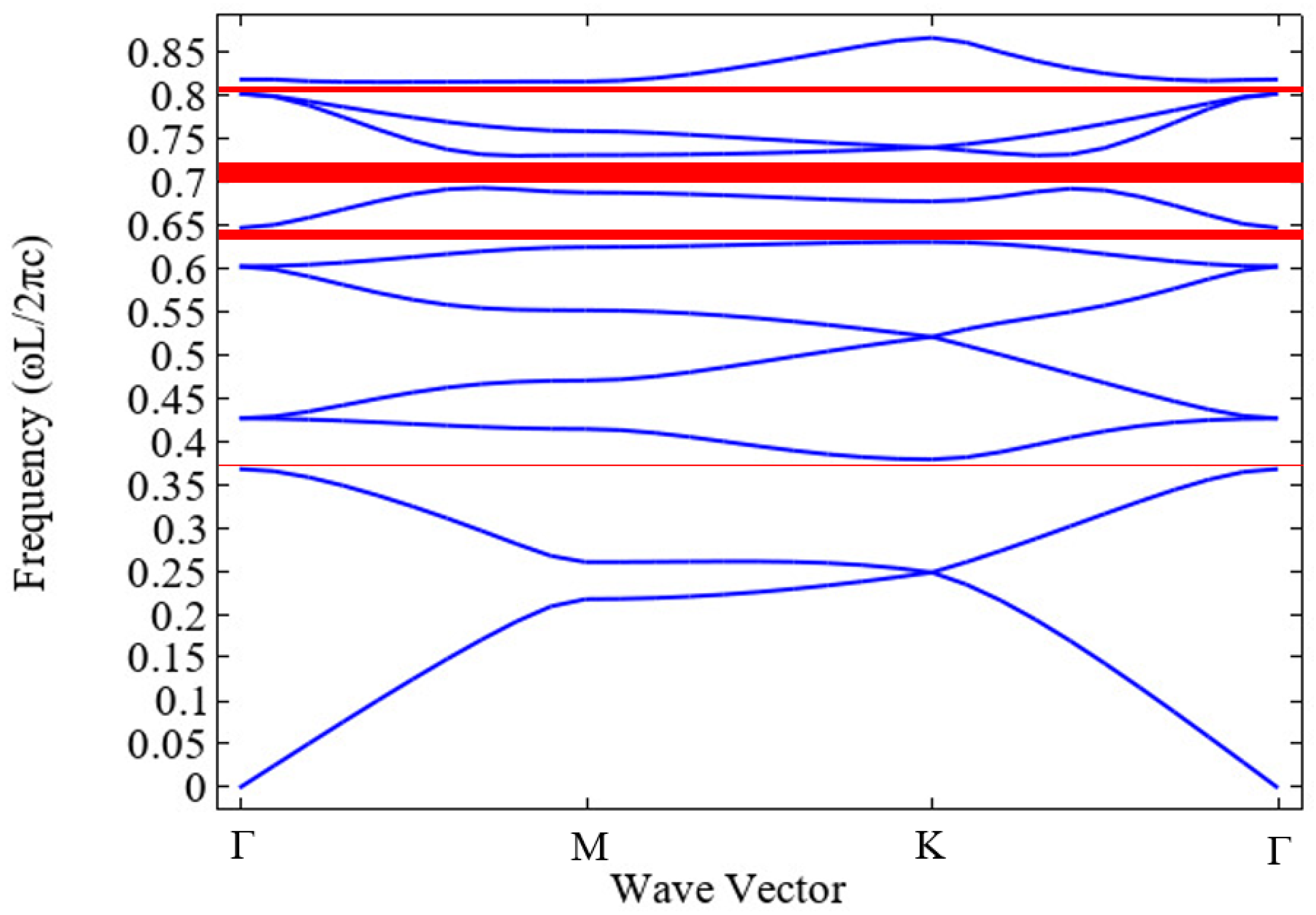
In order to study PCW, we first need to determine the energy band structure of the basic unit in them. We use the Plane Wave Expansion Method (PWEM) to calculate the E-polarization band structure of a triangular PhC in Figure 2. We can find that four band gaps appear in the band diagram. In addition, among them, the wider band gap appears at ω l / 2 π c = 0.7 , and three narrow band gaps appear at ω l / 2 π c = 0.38 , ω l / 2 π c = 0.62 and ω l / 2 π c = 0.81 . On the basis of the band diagram, the transmission spectrum of the Z waveguide can be further studied. Then, in the waveguide mode, we use an optimization method to maximize the transmittance of the objective function at wavelengths from 1440 nm to 1600 nm. The topology optimization method is implemented by calculating the independent relative moving distance of each air hole. The algorithm is implemented by using the free shape domain and free boundary technology to achieve gradient optimization. Consider that the planar photonic crystal structure is dense, which greatly increases the computational time even with the topological optimization method. The movement limit is set to 0.2 and the maximum iteration is set to 50.
Figure 3 shows the relationship between the transmission and wavelength of the conventional (blue line) and optimized (black line) Z-bending waveguide. Before optimization, the maximum loss is from −48 dB to −34 dB. This is because the waveguide can be approximated as a resonator at the bend, and the light wave will be localized at the bend. The localization can be effectively reduced by changing the arrangement of the air holes at the bend so that the PCW has better transmission characteristics. For a straight Z-bending waveguide, there are two inverted peaks at 1490 nm and 1571 nm, and the transmission bandwidth between the two peaks is 81 nm. For a curved Z-bending waveguide, several inverted peaks appear, and three of them are selected at wavelengths of 1483 nm, 1513 nm and 1563 nm. The transmission bandwidth between the inverted peaks at 1483 nm and 1513 nm is 30 nm. The transmission bandwidth between the inverted peaks at 1513 nm and 1563 nm is 50 nm. Although the transmittance of these two structures is already high, there is still room for improvement. In addition, the existence of the resonant structure will also cause a great drop in the transmission bandwidth. When we pay attention to the black line, i.e., the result after the topology optimization, we can find that the overall transmission spectrum is improved obviously; both forms of Z waveguides have a low loss of about −5 dB and a high bandwidth of about 160 nm. This result also shows the great advantage of topology optimization in the design of PCW.
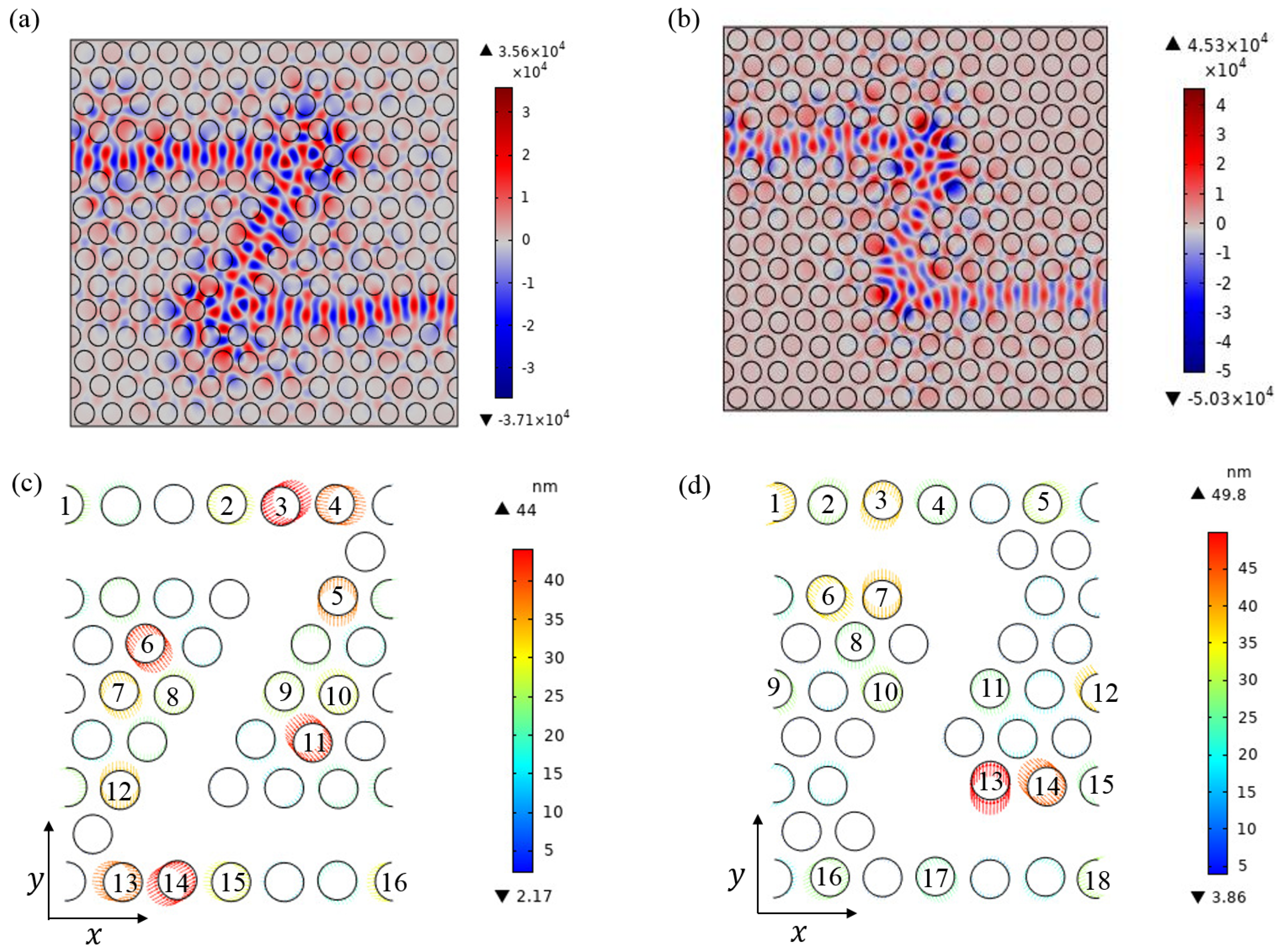
Through the method of topology optimization, the electric field diagram in the z direction of the Z waveguides at 1550 nm is simulated and calculated, as shown in Figure 4a,b. It can be seen that the electromagnetic field is well limited in the waveguide region. By means of topology optimization, the external reflection and scattering of a light wave can be well reduced. The topology optimization of the position of the hole at the bend is shown in Figure 5c,d. The two figures are the topology optimization diagram of a straight Z waveguide and a curved Z waveguide, respectively. The arrows on the air holes indicate the direction of movement, and the arrows in different colors indicate the movement distance of the air holes. In the straight Z waveguide, the maximum relative displacement of the bending part is 44 nm, and the minimum relative displacement is 2.17 nm. In the curved Z waveguide, the maximum relative displacement of the curved part is 49.8 nm, and the minimum relative displacement is 3.86 nm. The displacement coordinates of the air holes with the relative displacement of the straight Z waveguide greater than 25 nm is shown in Table 1, while the curved Z waveguide is shown in Table 2. In order to make the simulation more accurate, the relative displacement data are reserved to two decimal places. The results provide specific numerical simulation parameters for the improvement in the transmittance of the Z waveguide.
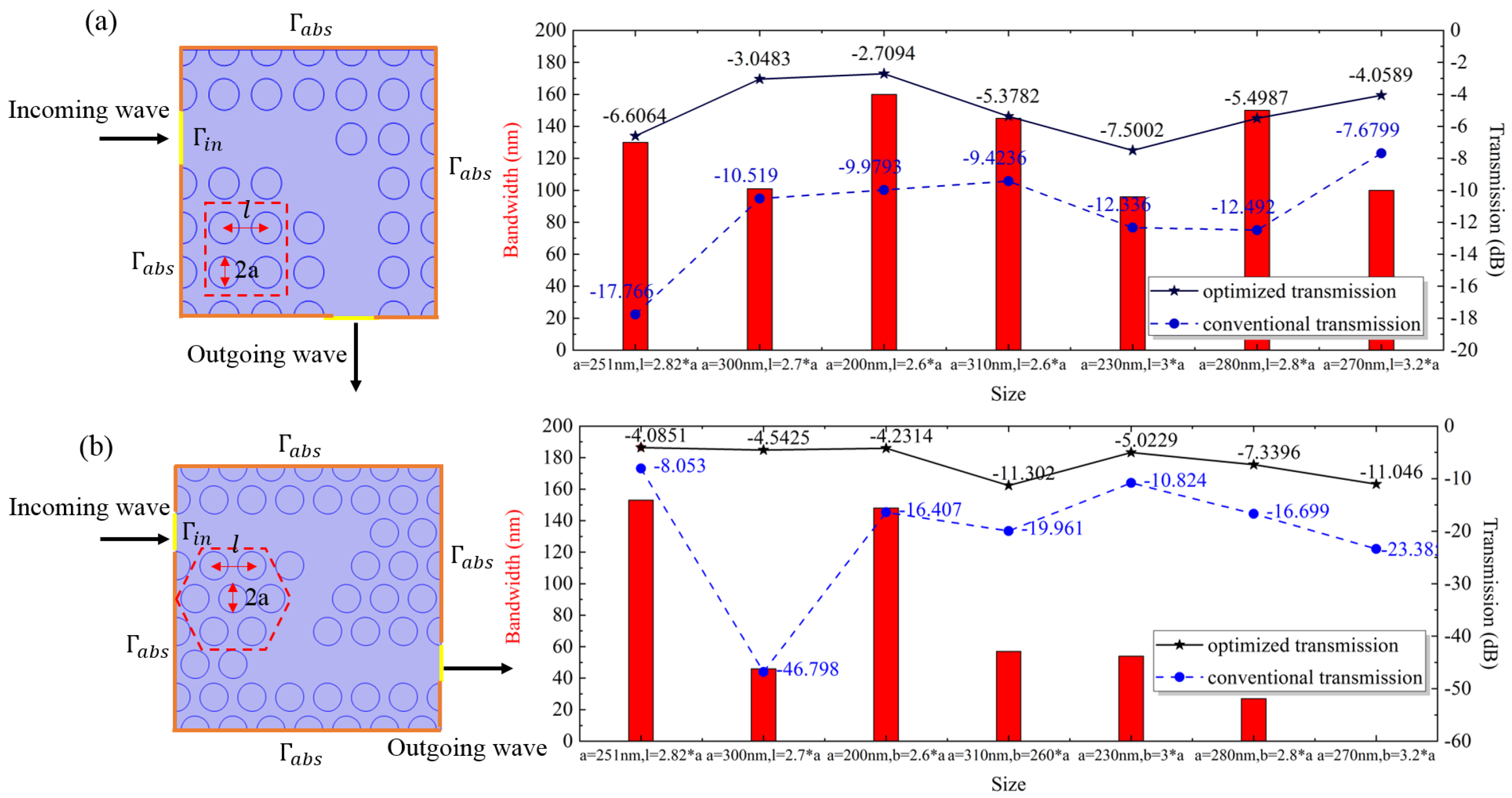
To further demonstrate the advantages of topology optimization in Z waveguide design, we optimized Z waveguides with different parameters. A 90° curved waveguide arranged in a rectangular lattice is studied in Figure 5a. The left panel shows the bandwidth with a transmission loss less than −6 dB at different sizes after the topology optimization. The right panel shows the transmission loss of the structure at 1550 nm under different air hole radius and lattice constants, before and after the topology optimization. We can find that after the topology optimization, the transmission loss of the system can be reduced to −6 dB and the bandwidth can be increased to 200 nm, which has greatly improved compared with the original structure. Z waveguide bending with a triangular lattice arrangement is shown in Figure 5b. Similarly, the transmission loss is reduced to −6 dB and the bandwidth reaches above 200 nm, just like the square lattice, and the transmission rate of the optimized system is more stable. This is due to the effects of the lattice arrangement and sharp bending. The topology optimization result is a black box, and the purpose of the design here is just to make its performance better. This result shows that our topology optimization scheme is beneficial to any 2D photonic crystal waveguide design. It also shows the potential of this approach for the design of other photonic crystal devices.

4. Conclusions

In this paper, we introduced topology optimization to design the low-loss, high-bandwidth two-dimensional photonic crystal Z waveguide structure. The simulation results show that the transmission characteristics can be effectively improved by independently changing the position of each hole of the bend. We use the Method of Moving Asymptotes (MMA) gradient optimization method to maximize the objective function. Through the topology optimization, the transmission loss is reduced to −5 dB and the bandwidth is stretched to 160 nm. Finally, we also verified the universality of this method in the design of photonic crystal waveguides, and the results show that the topology optimization method can be widely used in photonic crystal waveguides and photonic crystal devices.

Author Contributions

Conceptualization, G.L. and F.W.; methodology, G.L. and F.W.; software, G.L. and F.W.; validation, G.L. and F.W.; formal analysis, G.L. and F.W.; investigation, G.L. and F.W.; resources, G.L. and F.W.; data curation, G.L. and F.W.; writing—original draft preparation, G.L. and F.W.; writing—review and editing, G.L., F.W., Y.G., B.J., X.G., P.L. and H.S.; visualization, G.L. and F.W.; supervision, H.S.; project administration, G.L. and F.W.; funding acquisition, Y.G. All authors have read and agreed to the published version of the manuscript.

Funding

The National Key Research and Development Program of China (Grant 2021YFB3601201) and the National Natural Science Foundation of China for the support under Grant Nos. 62101057 and 62071448. The Fund of State Key Laboratory of Information Photonics and Optical Communications (Beijing University of Posts and Telecommunications) (No. IPOC2021ZT07), P. R. China.

Institutional Review Board Statement

Not applicable.

Informed Consent Statement

Not applicable.

Data Availability Statement

Data is unavailable due to privacy or ethical re-strictions.

Acknowledgments

We would like to thank the National Key Research and Development Program of China (Grant 2021YFB3601201) and the National Natural Science Foundation of China for the support under Grant Nos. 62101057 and 62071448. The project was supported by the Fund of State Key Laboratory of Information Photonics and Optical Communications (Beijing University of Posts and Telecommunications) (No. IPOC2021ZT07), P. R. China.

Conflicts of Interest

The authors declare no conflict of interest.

References

  1. Sakoda, K. Transmittance and Bragg reflectivity of two-dimensional photonic lattices. Phys. Rev. B 1995, 52, 8992. [Google Scholar] [CrossRef]
  2. Kefer, S.; Roth, G.L.; Zettl, J.; Schmauss, B.; Hellmann, R. Sapphire Photonic Crystal Waveguides with Integrated Bragg Grating Structure. Photonics 2022, 9, 234. [Google Scholar] [CrossRef]
  3. Yablonovitch, E. Inhibited spontaneous emission in solid-state physics and electronics. Phys. Rev. Lett. 1987, 58, 2059. [Google Scholar] [CrossRef] [PubMed]
  4. John, S. Strong localization of photons in certain disordered dielectric superlattices. Phys. Rev. Lett. 1987, 58, 2486. [Google Scholar] [CrossRef] [PubMed]
  5. Lourtioz, J.M.; Benisty, H.; Berger, V.; Gérard, J.; Maystre, D.; Tchelnokov, A.; Pagnoux, D. Photonic Crystals. Towards Nanoscale Photonic Devices; Springer: Berlin, Germany, 2006; pp. 121–122. [Google Scholar]
  6. Taya, S.A.; Ramahi, O.M.; Abutailkh, M.A.; Doghmosh, N.; Nassar, Z.M.; Upadhyay, A.; Colak, I. Investigation of bandgap properties in one-dimensional binary superconductor–dielectric photonic crystal: TE case. Indian J. Phys. 2022, 96, 2151–2160. [Google Scholar] [CrossRef]
  7. Ma, T.X.; Wang, Y.S.; Zhang, C. Investigation of dual photonic and phononic bandgaps in two-dimensional phoxonic crystals with veins. Opt. Commun. 2014, 312, 68–72. [Google Scholar] [CrossRef]
  8. Guo, H.; Hong, X.; Fan, H.; Fu, R.; Liu, X.; Li, Y.; Feng, S.; Chen, X.; Li, C.; Wang, Y. Polarization-independent waveguides based on the complete band gap of the two-dimensional photonic crystal slabs. Laser Phys. 2019, 29, 046205. [Google Scholar] [CrossRef]
  9. Butt, M.A.; Khonina, S.N.; Kazanskiy, N.L. 2D-Photonic crystal heterostructures for the realization of compact photonic devices. Photonics-Nanostruct.-Fundam. Appl. 2021, 44, 100903. [Google Scholar] [CrossRef]
  10. Zhao, Q.; Cui, K.; Huang, Z.; Feng, X.; Zhang, D.; Liu, F.; Zhang, W.; Huang, Y. Compact thermo-optic switch based on tapered W1 photonic crystal waveguide. IEEE Photonics J. 2013, 5, 2200606. [Google Scholar] [CrossRef]
  11. Khan, Y.; Noor, D.; Ullah, N.; Khonina, S.N.; Kazanskiy, N.L.; Butt, M.A. Design and Analysis of Femtosecond Laser-Generated Metasurface for Optical Filter Application. Photonics 2022, 9, 797. [Google Scholar] [CrossRef]
  12. Wang, P.Y.; Lai, Y.C.; Cheng, Y.C. Spatial Beam Filtering with Autocloned Photonic Crystals. Crystals 2019, 9, 585. [Google Scholar] [CrossRef]
  13. Jao, R.F.; Lin, M.C. Quantitative Analysis of Photon Density of States for One-Dimensional Photonic Crystals in a Rectangular Waveguide. Crystals 2019, 9, 576. [Google Scholar] [CrossRef]
  14. Wang, B.; Cappelli, M.A. A tunable microwave plasma photonic crystal filter. Appl. Phys. Lett. 2015, 107, 171107. [Google Scholar] [CrossRef]
  15. Djavid, M.; Monifi, F.; Ghaffari, A.; Abrishamian, M.S. Heterostructure wavelength division demultiplexers using photonic crystal ring resonators. Opt. Commun. 2008, 281, 4028–4032. [Google Scholar] [CrossRef]
  16. Wang, K.; Wang, H.; Wu, X.Y.; Zhang, Y.; Yang, D.; Jiao, R.; Wang, C. Ultrasound Sensing Using Packaged Microsphere Cavity in the Underwater Environment. Sensors 2022, 22, 4190. [Google Scholar] [CrossRef] [PubMed]
  17. Lu, B.; Fan, C.R.; Song, J.Y.; Wang, C. Optical Parametric Oscillation with Ultra-Low Power Threshold in a Dimer of Active-Passive Cavities. Crystals 2021, 11, 566. [Google Scholar] [CrossRef]
  18. Olthaus, J.; Schrinner, P.P.; Reiter, D.E.; Schuck, C. Optimal photonic crystal cavities for coupling nanoemitters to photonic integrated circuits. Adv. Quantum Technol. 2020, 3, 1900084. [Google Scholar] [CrossRef]
  19. Luna-Acosta, G.A.; Schanze, H.; Kuhl, U.; Stöckmann, H.J. Impurity effects on the band structure of one-dimensional photonic crystals: Experiment and theory. New J. Phys. 2008, 10, 043005. [Google Scholar] [CrossRef]
  20. Askari, M.; Momeni, B.; Soltani, M.; Adibi, A. Systematic design of wide-bandwidth photonic crystal waveguide bends with high transmission and low dispersion. J. Light. Technol. 2010, 28, 1707–1713. [Google Scholar] [CrossRef]
  21. Mekis, A.; Fan, S.; Joannopoulos, J.D. Bound states in photonic crystal waveguides and waveguide bends. Phys. Rev. B 1998, 58, 4809. [Google Scholar] [CrossRef] [Green Version]
  22. Sunil, N.; Jayakrishnan, V.; Somanathan, H.; Jha, A.K. Transmission Spectrum of a Typical Waveguide in Photonic Crystal with Tunable Width: Simulation and Analysis. In International Conference on Communications and Cyber Physical Engineering 2018; Springer: Singapore, 2018; pp. 203–209. [Google Scholar]
  23. Li, C.; Hu, X.; Gao, W.; Ao, Y.; Chu, S.; Yang, H.; Gong, Q. Thermo-optical tunable ultracompact chip-integrated 1D photonic topological insulator. Adv. Opt. Mater. 2018, 6, 1701071. [Google Scholar] [CrossRef]
  24. Zhao, Q.; Cui, K.; Feng, X.; Liu, F.; Zhang, W.; Huang, Y. Low loss sharp photonic crystal waveguide bends. Opt. Commun. 2015, 355, 209–212. [Google Scholar] [CrossRef]
  25. Yuan, J.; Yang, J.; Shi, D.; Ai, W.; Shuai, T. Design optimization of a low-loss and wide-band sharp 120° waveguide bend in 2D photonic crystals. Opt. Commun. 2016, 367, 356–363. [Google Scholar] [CrossRef]
  26. Borel, P.I.; Harpøth, A.; Frandsen, L.H.; Kristensen, M.; Shi, P.; Jensen, J.S.; Sigmund, O. Topology optimization and fabrication of photonic crystal structures. Opt. Express 2004, 12, 1996–2001. [Google Scholar] [CrossRef] [PubMed]
  27. Sayed, H.; Al-Dossari, M.; Ismail, M.A.; Abd El-Gawaad, N.S.; Aly, A.H. Theoretical Analysis of Optical Properties for Amorphous Silicon Solar Cells with Adding Anti-Reflective Coating Photonic Crystals. Photonics 2022, 9, 813. [Google Scholar] [CrossRef]
  28. Ren, G.; Zheng, W.; Zhang, Y.; Wang, K.; Du, X.; Xing, M.; Chen, L. Mode Analysis and Design of a Low-Loss Photonic Crystal 60° Waveguide Bend. J. Light. Technol. 2008, 26, 2215–2218. [Google Scholar] [CrossRef]
  29. Mekis, A.; Chen, J.C.; Kurl, I.; Fan, S.; Villeneuve, P.R.; Joannopoulos, J.D. High transmission through sharp bends in photonic crystal waveguides. Phys. Rev. Lett. 1996, 77, 3787. [Google Scholar] [CrossRef] [PubMed]
  30. Jensen, J.S.; Sigmund, O.; Frandsen, L.H.; Borel, P.I.; Harpoth, A.; Kristensen, M. Topology design and fabrication of an efficient double 90/spl deg/photonic crystal waveguide bend. IEEE Photonics Technol. Lett. 2005, 17, 1202–1204. [Google Scholar] [CrossRef]
  31. Jensen, J.S.; Sigmund, O. Topology optimization of photonic crystal structures: A high-bandwidth low-loss T-junction waveguide. JOSA B 2005, 22, 1191–1198. [Google Scholar] [CrossRef]
  32. Boscolo, S.; Conti, C.; Midrio, M.; Someda, C.G. Numerical analysis of propagation and impedance matching in 2-D photonic crystal waveguides with finite length. J. Light. Technol. 2002, 20, 304. [Google Scholar] [CrossRef]
  33. Konopsky, V. Design of 1D Photonic Crystals Sustaining Optical Surface Modes. Coatings 2022, 12, 1489. [Google Scholar] [CrossRef]
  34. Jin, J.M. The Finite Element Method in Electromagnetics; John Wiley & Sons: New York, NY, USA, 2015. [Google Scholar]
  35. Segovia-Chaves, F.; Vinck-Posada, H. Two-dimensional photonic crystals with insertion of circular and triangular defects. Optik 2021, 246, 167830. [Google Scholar] [CrossRef]
  36. Segovia-Chaves, F.; Vinck-Posada, H.; Navarro-Barón, E. Photonic band structure in a two-dimensional hexagonal lattice of equilateral triangles. Phys. Lett. A 2019, 383, 3207–3213. [Google Scholar] [CrossRef]
Figure 1. Z-bending waveguide in a finite PhC on triangle lattice: (a) straight Z waveguide; (b) curved Z waveguide. The radius of the air hole a = 251 nm, lattice constant l   =   2.82   *   a . The dark blue air holes show the difference between the two structures. The red box magnifies the size of the structure. The structure exhibits aperiodic distribution in the x y -plane. Light enters the PhC from the incident port and leaves the PhC from the outgoing port.
Photonics 10 00202 g001
Figure 2. Defined as the band structure of a PhC for E-polarization with triangular lattice air holes of radius r = 251 nm arranged in a silicon background. Ten bands are generated at a normalized frequency of zero and are represented by the blue line. The red line shows the PBG in the band diagram.
Photonics 10 00202 g002
Figure 3. Diagram of transmission spectrum as a function of light wavelength from 1440 nm to 1600 nm. (a) Straight Z waveguide; (b) curved Z waveguide. The blue dotted line for the un-optimized waveguide bend and the black solid line for the optimized waveguide bend. The red dashed line represents the relatively low transmission-loss part between the two inverted peaks defined. The wavelength of the defined inverted peak position is indicated by red numbers.
Photonics 10 00202 g003
Figure 4. The electric fields in z direction at 1550 nm in the (a) straight Z waveguide and the (b) curved Z waveguide. The radius of the air hole a = 251 nm, lattice constant l   =   2.82   *   a . Topology optimization diagram of (c) straight Z waveguide and (d) curved Z waveguide in the curved part. The arrows on the air holes indicate the direction of movement through topology optimization, and the arrows in different colors indicate the movement distance of the air holes. The numbers on the air holes indicate the air holes with the relative displacement greater than 25 nm.
Photonics 10 00202 g004
Figure 5. Transmission spectra of curved PCW with different structures at different sizes. (a) Rectangular 90° bending PCW; (b) triangular lattice structure Z curved PCW. The transmission spectrum shows the transmission-loss bandwidth of less than −6 dB after topology optimization of different sizes from 1440 nm to 1600 nm. The blue dashed line shows the transmission loss of conventional transmission at 1550 nm at different sizes; the solid black line shows the transmission loss at 1550 nm for optimized transmission at different sizes.
Photonics 10 00202 g005
Table 1. The displacement coordinates of the air holes with the relative displacement of the straight Z waveguide greater than 25 nm. Number is the number of the selected air holes. x and y represent the relative displacement of the selected air holes in different directions.
Numberx (nm)y (nm)Numberx (nm)y (nm)Numberx (nm)y (nm)Numberx (nm)y (nm)
1−25.040.072−27.605.593−37.89−22.344−38.265.78
52.0337.056−25.1233.177−12.8230.108−10.62−23.84
911.1223.581013.58−24.751127.30−31.78121.12−33.34
1337.57−5.381437.3521.511528.58−4.061629.103.97
Table 2. The displacement coordinates of the air holes with the relative displacement of the curved Z waveguide greater than 25 nm. Number is the number of the selected air holes. x and y represent the relative displacement of the selected air holes in different directions.
Numberx (nm)y (nm)Numberx (nm)y (nm)Numberx (nm)y (nm)Numberx (nm)y (nm)
134.8512.382−8.19−27.32310.7136.03413.88−23.44
5−27.70−12.726−26.7124.347−0.27−38.538−1.83−26.80
9−16.7722.971012.11−27.0111−6.9625.781221.08−30.67
130.9249.791432.17−30.281510.98−24.211625.2712.02
17−12.2822.0318−26.88−12.05
Disclaimer/Publisher’s Note: The statements, opinions and data contained in all publications are solely those of the individual author(s) and contributor(s) and not of MDPI and/or the editor(s). MDPI and/or the editor(s) disclaim responsibility for any injury to people or property resulting from any ideas, methods, instructions or products referred to in the content.