Abstract
The integration of 5G and vertical industries promotes the development of the energy Ethernet while putting forward fine granularity, flexibility, high reliability, and deterministic low-latency service requirements for the smart grid and the ubiquitous power Internet of Things (UPIoT). As the bearer architecture supporting the next-generation optical transmission network, the Slicing Packet Network (SPN) slice granularity decreases from 5 Gbps to 10 Mbps fine granularity and the frame period of 5 Gbps large-granularity slices is short, so the non-deterministic delay caused by timeslot conflicts has a negligible impact on the end-to-end delay, and the timeslot scheduling is unnecessary. However, due to the reduction in timeslot granularity and the change in frame structure in 10 Mbps slices, the scheduling of conflicting timeslots and the complex device computing management problems need to be solved urgently. In this paper, we establish a model of routing embedded timeslot scheduling for the routing of fine-granularity slices and timeslot scheduling problems in SPN-based FlexE interfaces, for which we propose a deterministic timeslot allocation mechanism supporting end-to-end low-latency transmission. According to the timeslot symmetry, the mechanism can reduce the space of feasible solutions through ant colony optimization and unidirectional neighborhood search (ACO-UNS), so as to efficiently solve the scheduling of conflicting timeslots and provide end-to-end delay guarantee for delay-sensitive services. Finally, we make a comparison between the ACO-UNS algorithm and the timeslot random dispatching algorithm (ACO-RD); the results show that, relative to the ACO-RD, the reduction in the proposed ACO-UNS is 98.721% for the end-to-end delay of fine-granularity slices.
1. Introduction
In recent years, data traffic has exploded, and diverse business requirements have driven changes in network technology. With the development of mobile communication, fifth-generation mobile communication technology (5G) is deeply integrated with various industries, and the emergence of diverse new business scenarios also requires the network to meet differentiated and customized business requirements. In this regard, the third-generation partnership project (3GPP) has identified enhanced mobile broadband (eMBB), massive Internet of things (MIoT), ultra-reliable and low-latency communication (URLLC), and vehicle-to-everything (V2X) as the four key scenarios [1,2]; meanwhile, 5G will continue to advance in vertical industries such as telematics, energy internet, smart grid [3], and the private line industry for government and enterprise. Industries are gradually developing into complex application situations and putting forward a demand for bringing small bandwidth services below 100 Mbps to the network.
In the field of power systems under the circumstances of the energy revolution, the power communication network is being gradually upgraded to automation and intelligence. In 2020, the State Grid Corporation of China (CSGC) took the construction of the strong smart grid and the ubiquitous power Internet of Things (UPIoT) as one of the most significant development strategies for the future [4] and also provided a comprehensive bearing for multiple links, such as power generation, transmission, and power transformation and distribution, by constructing a new power communication network.
However, in the face of the large bandwidth, low latency, high reliability, and other business requirements with the multi-dimensional characteristics of the energy Internet, the current power communication network has the following problems. First, the Synchronous Digital Hierarchy (SDH) fiber optic transmission network, which mainly carries 2M granularity control services in the current power grid, has the advantages of low latency and high reliability, but the upgrade of the dispatch network and the access network, increase the bandwidth demand for power services. Second, although the Optical Transport Network (OTN) can satisfy the demand for the large bandwidth, it is hard to satisfy the demands of fine granularity, and the cost of access to equipment is also higher, so the power communication network needs a more flexible technology to bear the services. Third, the widely used Packet Transport Network (PTN) technology lacks physical isolation of the transmission channel and therefore cannot satisfy the isolation demand of production control services and management information services [5,6].
Therefore, for the production control services and management information services that require fine granularity, deterministic delay, high reliability, and flexibility, China Mobile has launched the Slicing Packet Network (SPN) technology, which supports fine granularity [7]. It inherits the efficient Ethernet core of SPN [8] and mainly relies on network slicing and Flexible Ethernet (FlexE) to divide multiple logical channels on a physical network to achieve end-to-end hard slicing [9,10,11,12,13].
In this paper, we study the fine-granularity slices routing problem and the timeslot resources scheduling (RTS) problem in the SPN based on FlexE interfaces. When a service bearing in a network slice arrives, we need to assign the route based on the current network state and provide suitable timeslot resources on each link in the route for the service in order to guarantee the QoS of the differentiated service. It should be noted that with the reduction in frame granularity from 5 Gbps to 10 Mbps, the FlexE frame structure’s brand new Fine-Granularity Unit (FGU) sublayer, and the FGU further dividing and multiplexing the 5 Gbps timeslot [9], the number of timeslots handled by each forwarding node increases several times.
On the one hand, the frame period of 5 Gbps large granularity is short, so the non-deterministic delay caused by timeslot conflicts has a small, negligible impact on the end-to-end delay, and the timeslot scheduling is unnecessary. However, the change in the 10 Mbps frame structure increases the frame period, so the non-deterministic delay caused by timeslot conflict is relatively large, which cannot be ignored. In order to guarantee the QoS of delay-sensitive services, the timeslot scheduling must be performed for 10 Mbps fine-granularity slices. On the other hand, the reduction in granularity and the change in the frame structure, respectively, bring about critical issues of significantly increasing the number of slices and enlarging the decision space of resource allocation, which aggravate the complexity of device computing management.
Therefore, it is hard to guarantee the QoS of services with deterministic delay due to the large scheduling delay if the timeslots are not properly arranged. We need a scheme to solve the RTS problem of the fine-granularity slices in the SPN based on FlexE interfaces. Although prior research has considered the slices routing problem in the SPN [14], the allocation and schedule of timeslot resources for fine granularity has not been considered.
The main contributions of this paper are as follows.
We formulate a routing-embedded timeslot scheduling (RETS) model for fine-granularity slices, with the purpose of minimizing the end-to-end latency of service slices. To the best of our knowledge, this paper is the first to investigate the RTS problem for fine-granularity slices in the SPN based on FlexE interfaces.
We propose a routing and deterministic timeslot allocation mechanism supporting end-to-end low latency transmission based on ant colony optimization and unidirectional neighborhood search (ACO-UNS), which successfully solves the RTS problem.
We evaluate the performance of the proposed algorithm with real network data and compare it with the timeslot random dispatching algorithm (ACO-RD). Results show that the ACO-UNS we propose outperforms the current ACO-RD for reducing the end-to-end delay of fine-granularity service slices.
The rest of the paper is organized as follows. Section II describes the RTS problem in the SPN based on FlexE interfaces and presents the RETS model in detail. Section III presents the ACO-UNS algorithm, including the pre-allocation scheme for timeslots and the dispatching scheme for conflict timeslots. Section IV shows the simulation results of the proposed algorithm and compares it with another existing algorithm, and Section V concludes this paper.
2. Related Works
SPN fine granularity inherits the efficient Ethernet core of SPN and integrates fine-granularity slicing into the overall SPN architecture through hierarchical design [7]. As shown in Figure 1a, the SPN network supporting fine granularity is divided into three layers: the Slicing Packet Layer (SPL), the Slicing Channel Layer (SCL), and the Slicing Transport Layer (STL). The SPL is mainly responsible for grouping service routing; the SCL has a new FGU sublayer, which provides a hard slicing channel based on N×10 Mbps for fine-granularity service bearers to realize the networking for end-to-end slicing channel in the L1 layer; and RTS problems for fine-granularity slicing studied in this paper are realized in this layer. The lowest STL can provide a physical layer bearer for SCL based on FlexE Group and IEEE 802.3 Ethernet (PMA and PMD). Meanwhile, ITU-T standards G.8310 and G.8312 [15,16] stipulate that the bandwidth of the timeslot provided by the SCL is 5 Gbps, and in the SPN fine-granularity structure, the FGU sublayer further divides and multiplexes the 5 Gbps timeslot, each FGU multi-frame includes 480 sub-slots, as shown in Figure 1c.
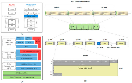
Figure 1.
(a) The fundamental architecture of FlexE. (b) The SPN architecture that supports fine-granularity technology. (c) The FGU frame structure of FlexE N×10 Mbps.
The fundamental architecture of FlexE is shown in Figure 1b [9], which introduces the FlexE Shim between the MAC and the PHY layer based on the existing IEEE802.3 standard. The FlexE Shim performs the essential functionalities of FlexE and is primarily responsible for organizing and distributing the data streams of FlexE Clients to the FlexE PHY. It also supports rate adaptation among FlexE Clients and the insertion and extraction of FlexE overhead frames. Furthermore, based on the TDM, FlexE supports the mapping and transmission of any multiple sub-interfaces at the FlexE PHY, thus realizing the port bundling, sub-rate, and channelization. It breaks the limitation that the MAC layer only matches the rate of existing PHY layer interfaces in the standard Ethernet architecture, improves resource utilization, and realizes flexible matching of network interfaces.
On the one hand, with the development and evolution of FlexE, the technology is gradually being investigated in a variety of types of network transmission scenarios. FlexE technology is used in FlexE-over-WDM. A. Eira et al. address the application of FlexE to dense wavelength division multiplexing (DWDM) transport scenarios and proposes Greedy-based heuristic algorithms to solve cross-layer planning problems [17]. D. Koulougli et al. considered a multilayer multi-domain FlexE-over-WDM scenario and proposed two efficient algorithms to solve the routing and FlexE allocation problems for multilayer multi-domain networks, respectively [18,19]. K. Wu et al. in [20] proposed a FlexE-over-WDM network architecture based on frame replication and elimination for reliability (FRER) and designed a redundant routing provision based on S-FRER to effectively condense the network redundancy. Then, the authors further designed the E-FRER and O-FRER algorithm for comparison with S-FRER and proposed a FlexE Group allocation strategy based on segmented frame repetition and elimination in [21], which realized the resource redistribution of service flows on redundant routes. FlexE technology is also used in FlexE-over-EON. H. Liang et al. proposed a PDIP-Based Approximation Algorithm to solve the FlexE-over-EON cross-layer network-planning problem based on the FlexE-Unware architecture [22]. Furthermore, in the SPN based FlexE interfaces, D. Wu et al. proposed an end-to-end routing strategy, Q-Learning-Slice Management Balance (QL-SMB), for slice balance management in view of the management and calculation difficulties caused by the increase in fine-granularity slices, which effectively improves network performance [14].
On the other hand, the flexibility of FlexE can enhance the network restoration. D. Koulougli et al. investigate the FlexE Traffic Restoration (FTR) problem, which aims to maintain high network utilization with the fast recovery of FlexE clients with the minimum cost using the spare capacity in the already deployed PHYs [23]. M. Wu et al. proposed an auxiliary graph (AG)-based algorithm to solve the cross-layer restoration (CLR) problem in FlexE-over-EON, which effectively reduces the OPEX [24]. FlexE can also avoid eavesdropping attacks at the PHY, and it enables end-to-end secure transmission across layers [25,26].
In addition, the port bundling, sub-rate, and channelization capabilities, as well as the dynamic and scalable advantages of the FlexE, help to solve key problems in vertical industries. J. Song et al. designed a service hosting device based on the FlexE with 10 Mbps granularity slicing for the service requirements of the energy Internet and the problems in networking [27]. In order to satisfy the demand for new power communication services, Z. Ding et al. presented a FlexE slicing network architecture and proposed a network bearer scheme for typical power grid application scenarios [28].
In the application of 5G in vertical industries, SPN fine-granularity technology has shown great commercial value. Operators and enterprises are continually promoting it in the contexts of smart grid [29], intelligent transportation, and smart cities [7]. In addition, in response to the demand for flexible bandwidth and high security for private-line services, SPN fine-granularity technology is also widely used in government, financial, and enterprise contexts. The capability of SPN fine-granularity slicing has rich industrial prospects, which will facilitate its deployment in 5G+ vertical industries and private line industries.
3. System Model
In this section, we first present the network model of the SPN-based FlexE interfaces, then describe in detail the RTS problem in the SPN-based FlexE interfaces, and finally propose the innovative RTES model.
3.1. Network Presentation
An SPN-based FlexE interface can be represented by a directed graph , where represents the set of nodes, indicates that the number of the nodes is , and represents the set of links in the network. In addition, the adjacent nodes are connected by two links in opposite directions; for example, denotes the link from node to node , and denotes the link from node to node . The link length sets are defined as , and represents the link bandwidth sets in the FlexE.
3.2. Routing and Timeslot Scheduling Problem in the SPN Based on FlexE interfaces
When SCL implements end-to-end network slicing through FlexE hard isolation, network slicing needs to bear multiple services. When a service borne in a network slice arrives, we should first assign the route based on the current network state, then pre-allocate the timeslot resources on each link in the route for the service; however, if the pre-allocated timeslot resources are already occupied, we need to dispatch other timeslot resources to bear the service slices in order to guarantee the QoS of the differentiated service.
Let us take a look at a simple example where there is a service that needs to occupy one timeslot and a service that needs to occupy two timeslots. Both of them need to establish an end-to-end connection from Node A to Node G. At this time, we assume that there are two paths, Path I and Path II, available for routing, and the timeslots marked in gray cannot be used because they have occupied by other services. Through the pre-allocation of timeslot resources and the dispatching of the conflicting timeslot, the timeslot positions occupied by the service slices on different routes are shown in Figure 2.
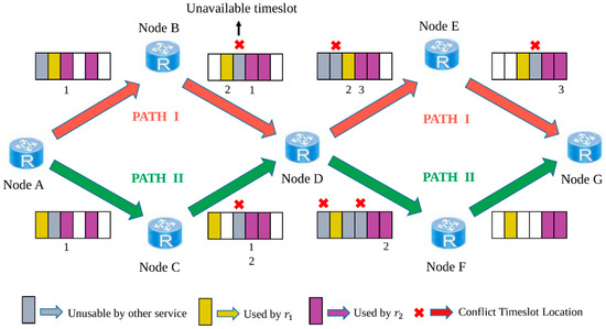
Figure 2.
Routing and timeslot allocating and dispatching in FlexE.
Our objective is to minimize the end-to-end delay (EED) that can meet the low latency demand for the fine granularity and high reliability of services in the era of 5G + vertical industries, and we define the EED as Equation (1):
where is the sum of the propagation delay generated by the service, is the forwarding delay generated by the service at the intermediate nodes in the path due to timeslot crossover, and is the dispatching delay caused by the service due to timeslot conflict.
3.3. Routing Embedded Timeslot Scheduling Model
For any service request in the SPN-based FlexE interfaces’ connection request sets, we represent it by a triple , where denotes the source node, denotes the destination node, and denotes the bandwidth required by the service. Additionally, for the service request , we define the service path as , where is composed of K pre-computed paths . In addition, we assume that the service is transmitted from the source node to the destination node with the intermediate nodes only considering the forwarding method of timeslot crossing.
The timeslot occupancy of the FlexE frames transmitted on the link is represented by an array , where each binary bit of the array represents the occupancy of the timeslot of the corresponding frame, where a value of “0” means that the timeslot is available in the idle state, a value of “1” means that the timeslot is occupied, and denotes the total number of timeslots in each FlexE frame. In addition, we assume that there are already some services in the network occupying part of the link’s timeslot resources.
We derive a formulation shown in Equation (1) to compute the end-to-end path for the service and then allocate and dispatch the appropriate timeslot resources for each link in the path to minimize the EED of the service. The mathematical description of the RETS model is as follows.
Objective:
Constraints:
where indicates the EED of service on the path from the source node to the destination node , indicates the physical length of the link , and represents the transmission rate in the optical fiber.
The constraint in Equation (3) states that there is a routing continuity constraint from the source node to the destination node for the service , where is a binary variable equal to 1 if the routing path occupies the link and equal to 0 otherwise. The constraint in Equation (4) ensures that the service occupies the same size of bandwidth resources on different links and through in the route.
The constraint in Equation (5) indicates that the number of frame timeslots allocated in a link for the service needs to be less than the actual number of timeslots, where denotes the number of timeslots required in the link for the service and denotes the total number of timeslots in each FlexE frame. The constraint in Equation (6) provides the number of timeslots required for the service .
Finally, the constraint in Equation (7) indicates that the timeslot of each link is allowed to carry only one data code block of one service at a certain moment, and the variable is equal to 1 if the service contains link of path and equal to 0 otherwise, while the variable is equal to 1 if the timeslot of the link is occupied and equal to 0 otherwise.
It should also be noted that there is no timeslot continuity and timeslot consistency constraint for the RTS problem in the SPN based on FlexE interfaces.
4. Algorithm Design
In this section, we propose an ACO-UNS algorithm for the RTS problem of large-scale FlexE networks, which takes EED minimization as the optimization objective and integrates routing and timeslot resource allocation and dispatching schemes to find the optimal solution. The relevant symbols involved in the algorithm and their corresponding descriptions are shown in Table 1.

Table 1.
Notations.
The ACO-UNS algorithm solves the routing problem with the help of a positive feedback mechanism in the process of ant colony searching and solves the timeslot scheduling problem with the unidirectional neighborhood search method. The algorithm flow is shown in Figure 3. In particular, each ant selects a path from the source node during the iteration, and whenever it finds the next node, the allocation and dispatching of timeslot resources are performed on that path. The flow of step “Timeslot allocation and dispatching” in Figure 3 is shown in Figure 4. When it reaches the end node finally, it records the EED of the path and performs several iterations of the algorithm to find the optimal solution.
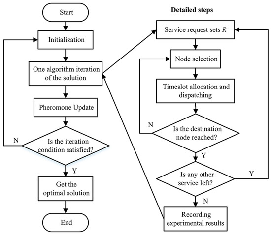
Figure 3.
The flow chart of ACO-UNS algorithm.
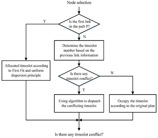
Figure 4.
Unidirectional neighborhood search method of the step “timeslot allocation and dispatching”.
4.1. Initialization
The initialization process sets parameters for the whole algorithm, where the maximum number of iterations of the algorithm is and the initial pheromone concentration of each link , and for the network topology , we established the inter-node propagation delay matrix . Setting the algorithm parameters correctly is crucial to enhance the performance of the algorithm.
4.2. Node Selection
As the ant moves from the source node to the destination node, it will randomly select the next node according to the state transfer function shown in Equation (8).
where denotes the node that the ant q can choose next, is a taboo table that records the nodes that the ant has already traveled, represents the importance of the pheromone, and represents the importance of the expectation.
where is the propagation delay of service in the link , is the delay between the sending node sending the first bit on the physical link and the arrival of that bit at the receiving node, is the timeslot forwarding delay of each node in the path, and is the delay of the timeslot dispatching triggered by the conflicting slot. The expectancy heuristic factor is set to the inverse of the propagation delay of the link when the ant passes through a link starting from the source node; when the ant passes through other links, the is set to the inverse of the total of the propagation delay, the link’s dispatching delay, and the starting node’s forwarding delay of that link.
4.3. Timeslot Allocation and Dispatching
When the ant passes through the first link from the source node, we use the First Fit (FF) algorithm to find the first available timeslot in the link and allocate the timeslot resources that are required according to the principle of equal allocation. Then, the timeslot location of the first link is noted as , where . For the links passing through the link except the first one, we consider that the timeslot allocation to be related to the propagation delay and the forwarding delay of the node to the service; thus, the position of timeslot occupied by service at the link can be represented by (10).
where is the dispatching delay of a sub-timeslot.
At this time, if the initially allocated timeslot position on the link is occupied by the services existing in the network, it is necessary to perform timeslot dispatching for the conflicting timeslots, and this section proposes a unidirectional neighborhood search conflict-avoidance timeslot-dispatching method in Algorithm 1.
| Algorithm 1: Unidirectional neighborhood search conflict-avoidance timeslot-dispatching method | |
| Input: Service , frame period , number of timeslots required for service , timeslot number assigned at the link of path , timeslot occupation . | |
| Output: Timeslot dispatch schemes for each link | |
| 1: | |
| 2: | |
| 3: | for link do |
| 4: | |
| 5: | |
| 6: | while do |
| 7: | if do |
| 8: | Start from and look for the position where in the direction of timeslot propagation |
| 9: | |
| 10: | |
| 11: | end if |
| 12: | |
| 13: | end while |
| 14: | |
| 15: | |
| 16: | |
| 17: | end for |
| 18: | return |
Algorithm 1 details the dispatching process of the unidirectional neighborhood search conflict-avoidance timeslot dispatching algorithm, which guarantees the minimized dispatching delay by performing an equivalent timeslot search in the direction of the frame timeslot propagation.
4.4. Pheromone Update
The behavioral characteristics of ant colonies show that when ants are blocked or reach their destination, a part of the pheromone will be left at each link, and the pheromone will evaporate over time to update the pheromone concentration of the whole topology. The iterative equation of the global pheromone concentration is shown in Equation (11).
where denotes the concentration of pheromone left on the link by the ant during the pathfinding. When the link through which the ant passes is the first link in the path, the pheromone concentration left by the ant is ; when the rest of the links other than the first link are passed, the pheromone concentration left is ; and finally, when the update of the global link is completed, the next iteration starts.
5. Simulation and Analysis
In this section, we first describe the settings of the experimental parameters and the simulation environment; then, we perform extensive simulation work to evaluate the performance of the algorithm proposed in the paper. We investigate the impact on FlexE timeslot dispatching in terms of four parameters—the load of network background services, service bandwidth, routing hops, and network size—and we draw a contrast between the conventional-timeslot random-dispatching algorithm ACO-RD and the ACO-UNS algorithm we proposed in terms of end-to-end dispatching delay. Finally, we present the simulation results and analysis.
We mainly used Python programming to build network scenarios and implement the algorithm ACO-UNS presented in this paper. All simulations involved in this section are run on a computer with a 2.2 GHz Intel Core i7 CPU and 16 GB of RAM. For the setting of the FlexE frame granularity, we take N×10 Mbps in the following simulation. In addition, the operation parameters of the algorithm are set as = 0.2, = 1.5, = 0.48, and = 1100 according to Equation (8) and Equation (12).
(a) Impact of Network Load on Dispatching Delay
To be able to evaluate the impact of the network load on the dispatching delay in a complex and network topology close to a real one, we perform the simulation on a real power-communication network topology at a location shown in Figure 5, first generating multiple sets of timeslot occupancy cases from 10% load to 80% load, for each link in the topology, at 10% intervals.
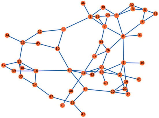
Figure 5.
Real power communication network topology of a city—50 nodes, 75 bidirectional fiber links.
Assuming that each node has the same hardware device, we set the forwarding delay for FlexE frames at each node; meanwhile, for a more comprehensive comparison of the algorithm performance, we implemented the conventional FlexE timeslot random-dispatching algorithm ACO-RD.
We first placed a service with a fixed bandwidth in the topology and calculated the service route and end-to-end dispatching delay by the ACO-UNS algorithm we proposed with multiple sets of timeslot-occupied cases by different loads, respectively, and the ACO-RD calculates the end-to-end scheduling delay by using a random allocation method for the timeslots of each link in the routing calculated by the ACO-UNS algorithm we proposed. Finally, we compared the data results and performed an analysis.
Figure 6 shows the comparison of the FlexE dispatching delay between the ACO-UNS algorithm and the traditional ACO-RD algorithm for a service with a fixed bandwidth and the same routing hop but different network loads. From the results, it can be seen that for the same topology, the end-to-end dispatching delay of the service calculated by both algorithms increases with the network load, which is because, according to the unidirectional neighborhood search mechanism, the increase in the network load will reduce the number of feasible timeslots solution.
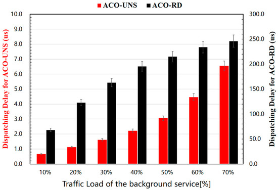
Figure 6.
The relationship between the load of background services and the dispatching delay.
In addition, compared with the reference algorithm, the end-to-end dispatching delay of the services calculated by the ACO-UNS is reduced by about 98.572%, which indicates that the algorithm we proposed is significantly better than the comparison algorithm in terms of comprehensive network performance optimization.
(b) Impact of Service Bandwidth on Dispatching Delay
In this section, we still use the real power communication network topology of a city shown in Figure 5 as the experimental topology to study the relationship between service bandwidth and end-to-end dispatching delay.
We set the load of each communication node in the network to 40 percent, generated the timeslot occupancy cases of multiple groups of background services, varied the service bandwidth from 50 Mbps to 350 Mbps in 50 Mbps intervals during the simulation, then calculated the service routing and end-to-end dispatching delay. Meanwhile, a random dispatching strategy was employed for the conflicting timeslots of each link on the service routing to determine the end-to-end dispatching delay of the service and compare with them; finally, the other simulation parameters were set to be the same as in simulation (a).
Figure 7 shows the comparison results of the end-to-end dispatching delay between the two timeslot allocation and dispatching schemes of the ACO-UNS and the ACO-RD for services with different bandwidths under the same network load and the routing hops, respectively. This is because the timeslots to be allocated and dispatched will increase with the increase in the service bandwidth, which causes the decrease in the available timeslots in feasible solutions space for each timeslot according to the unidirectional neighborhood search mechanism; therefore, the probability of the timeslot conflict and the end-to-end dispatching delay of the service will increase under the same load.
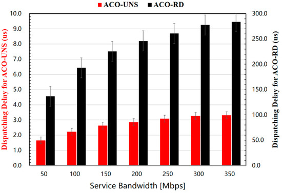
Figure 7.
The relationship between the load of background services and the dispatching delay.
Moreover, compared with the comparison algorithm, the end-to-end dispatching delay of ACO-UNS for the same service is reduced by about 98.827%, which indicates that the algorithm we propose in the paper is significantly better than the comparison algorithm in terms of network performance improvement.
(c) Impact of Routing Hops on Dispatching Delay
In the actual power communication network, the factors affecting the end-to-end dispatching delay are usually messy due to the complexity and variability of the power communication lines. Additionally, as one of the important factors affecting the quality of service of the communication network, it is important to study the relationship between the services with different routing hops and the end-to-end dispatching delay.
The routing hops are the number of relay routes that pass from the source node to the destination node, and in this section, we randomly select a sufficient number of services such that all services have 1 to 11 routing hops in the IEEE Power Bus–System communication network topology with 118 nodes, as shown in Figure 8. Then, we set the network load to 40% for each communication node in the network, and to exclude the chance of experimental results, we randomly generate the timeslot occupancy cases of multiple groups of background services and calculate the end-to-end dispatching delay based on the ACO-UNS we proposed in the paper.
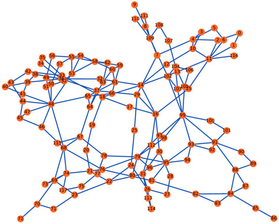
Figure 8.
IEEE 118 Power Communication Topology—118 nodes, 175 bidirectional fiber links.
Meanwhile, we apply the ACO-RD algorithm to allocate and dispatch the positions of the conflicting timeslot in each link and calculate the end-to-end dispatching delay; in addition, we also compare the simulation time with the ACO-UNS algorithms results, and other simulation parameters are set the same as in simulation (a).
With the same network load and the same service bandwidth, the relations between the average end-to-end dispatching delay and the routing hops are shown in Figure 9, which shows the results calculated by using the ACO-UNS algorithm and the SD algorithm. Figure 9 also compares the simulation time of the ACO-UNS we proposed and the ACO-RD.
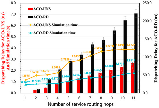
Figure 9.
The relationship between the routing hops of services and the dispatching delay.
The results show that the end-to-end dispatching delay and the simulation time increase with the routing hops, whether using the ACO-UNS or the ACO-RD to deal with the allocation and the dispatching of the timeslot. In addition, the ACO-UNS we proposed in the paper, the former algorithm reduces the service end-to-end dispatching delay by about 98.676% compared with the ACO-RD for the same number of routing hops, which indicates that the algorithm we proposed can better improve the comprehensive performance of the power communication network.
(d) Impact of Network Size on Dispatching Delay
We randomly generated several networks of different sizes but with the same structure using a scale-free algorithm [30,31] and set the size of network nodes to . In this subsection, we will use these networks to analyze the effect of network size on service end-to-end dispatching delay.
To exclude the influence of other variables, we set the load rate to 40 percent for each communication node in different network topologies, and randomly generated the timeslot occupancy cases of multiple groups of background services while distributing a large amount of services with the same service bandwidth and the same routing hops in each topology. Then, we calculated the routing and the end-to-end dispatching delay, in addition to which we evaluated and compared the running time of the algorithm, and the evaluation results are shown in Table 2.

Table 2.
Comparison of dispatching delay and simulation time of ACO-UNS and ACO-RD with varying network sizes.
According to the results, the complexity and the average simulation time of the algorithm for solving the RTS problem in FlexE increase significantly as the network scale rises. However, the end-to-end dispatching delay of services with the same routing hops and bandwidth is basically the same for different network scales. It was found that the reason for the above phenomenon is that the end-to-end dispatching delay of the service is only related to the timeslot distribution of the background services after analysis. The change in the network load and the service bandwidth will have an impact on the timeslot distribution, then affecting the end-to-end dispatching delay of the services, while the change in the network size is not related to the service end-to-end dispatching delay.
Finally, we compare the results of the ACO-UNS we proposed and the ACO-RD algorithm; the ACO-UNS reduces the service end-to-end dispatching delay by about 98.809% in different networks’ size, which indicates that the algorithm proposed in this paper can improve the comprehensive performance of power communication networks.
6. Summary
In conclusion, we have proposed a routing and conflict timeslot dispatching algorithm based on ant colony optimization and unidirectional neighborhood search (ACO-UNS) for the routing of fine-granularity slices and timeslot scheduling (including timeslot resources’ pre-allocation and dispatching) problems in the SPN based-FlexE interfaces, which ensured the minimum end-to-end delay for deterministic delay services. In addition, we studied the effects of network load, service bandwidth, routing hops, and network size on timeslot resource allocation and compared the ACO-UNS with the conventional timeslot random dispatching algorithm ACO-RD. The simulation results indicate that the ACO-UNS we proposed in this paper showed a comprehensive improvement of 98.721% for end-to-end delay relative to the ACO-RD. For future work, the authors are planning to a conduct further study on the timeslot resource seizure problem for dynamic services, which is essential for practical applications in the SPN-based FlexE interfaces scenarios.
Author Contributions
Conceptualization, R.G. and Z.W.; methodology, R.G. and Z.W.; validation, R.G., Y.X. and Z.W.; formal analysis, Y.X. and Z.W.; investigation, R.G., H.Z., Y.Y. and Y.L.; resources, Y.Z., H.Z. and Y.L.; data curation, Y.X. and Z.W.; writing—original draft preparation, Z.W. and Y.X.; writing—review and editing, R.G. and Y.J.; visualization, R.G. and Z.W.; supervision, Y.Z., H.Z. and Y.L.; project administration, R.G., Y.Z. and H.Z.; funding acquisition, R.G., Y.Z. and H.Z. All authors have read and agreed to the published version of the manuscript.
Funding
This work was jointly supported by National Natural Science Foundation of China (61971070), and Science and Technology Project For Young Talents of State Grid Shandong Electric Power Company (2022A-121), P. R. China.
Institutional Review Board Statement
Not applicable.
Informed Consent Statement
Not applicable.
Data Availability Statement
Not applicable.
Conflicts of Interest
The authors declare no conflict of interest.
References
- 3GPP. System Architecture for the 5G system (5GS); Version 16.4.0, Technical Specification (TS) 23.501, 3rd Generation Partnership Project (3GPP); 3GPP: Sophia Antipolis, France, 2020. [Google Scholar]
- 3GPP. Service Requirements for the 5G System; Version 17.2.0, Technical Specification (TS) 22.261,” 3rd Generation Partnership Project (3GPP); 3GPP: Sophia Antipolis, France, 2020. [Google Scholar]
- 5G PPP. 5G Empowering Vertical Industries, February 2016. Available online: https://5g-ppp.eu/wp-content/uploads/2016/02/BROCHURE_5PPP_BAT2_PL.pdf (accessed on 30 December 2022).
- Jun, L. Implementing innovation-driven development strategy and supporting the company’s ‘three types, two networks’ construction. State Grid News 2019, 06, 3–4/9. [Google Scholar]
- Xu, J.; Zhang, H.; Xue, C.; Liu, H.; Li, M.; Liu, J.; Zhang, Q. Testing application of SPN technology in power communication systems. In Proceedings of the 18th International Conference on AC and DC Power Transmission (ACDC 2022), Online Conference, 2–3 July 2022; pp. 1295–1301. [Google Scholar] [CrossRef]
- Feifei, Z.; Yingli, H.; An, L.; Peng, C.; Zhenqi, F.; Liyuan, A.; Yuhang, L.; Jingzhu, L. Research and application of FlexE technology in energy internet. Power Inf. Commun. Technol. 2022, 20, 70–78. [Google Scholar] [CrossRef]
- China Mobile. White Paper of SPN Fine Granularity Unit; China Mobile: Hong Kong, China, 2021. [Google Scholar]
- Proposal of Architecture of Slicing Packet Network (SPN) for 5G Transport; Jan. 2018: ITU-T SG 15 Contribution 678; ITU: Geneva, Switzerland, 2018.
- Optical Internetworking Forum. Flex Ethernet 2.2 Implementation Agreement. 2021. Available online: https://www.oiforum.com/wp-content/uploads/OIF-FLEXE-02.2.pdf (accessed on 30 December 2022).
- Li, X.; Samaka, M.; Chan, H.A.; Bhamare, D.; Gupta, L.; Guo, C.; Jain, R. Network Slicing for 5G: Challenges and Opportunities. IEEE Internet Comput. 2017, 21, 20–27. [Google Scholar] [CrossRef]
- Ordonez-Lucena, J.; Ameigeiras, P.; Lopez, D.; Ramos-Munoz, J.J.; Lorca, J.; Folgueira, J. Network Slicing for 5G with SDN/NFV: Concepts, Architectures, and Challenges. IEEE Commun. Mag. 2017, 55, 80–87. [Google Scholar] [CrossRef]
- de Foy, X.; Rahman, A. Network Slicing—3GPP Use Case; Working Draft; IETF: Wilmington, DE, USA, 2017. [Google Scholar]
- Afolabi, I.; Taleb, T.; Samdanis, K.; Ksentini, A.; Flinck, H. Network Slicing and Softwarization: A Survey on Principles, Enabling Technologies, and Solutions. IEEE Commun. Surv. Tutor. 2018, 20, 2429–2453. [Google Scholar] [CrossRef]
- Wu, D.; Xin, P.; Liu, L.; Bai, H.; Zhang, Y. Routing Policy for Balanced Management of Slices Using Flexible Ethernet. In Proceedings of the 2022 7th International Conference on Computer and Communication Systems (ICCCS), Wuhan, China, 22–25 April 2022; pp. 537–542. [Google Scholar] [CrossRef]
- Architecture of the Metro Transport Network—Corrigendum 1, ITU-T Recommendation G.8310. 2022. Available online: https://handle.itu.int/11.1002/1000/14907 (accessed on 30 December 2022).
- Interfaces for Metro Transport Networks—Amd. 1, ITU-T Recommendation G.8312. 2022. Available online: https://handle.itu.int/11.1002/1000/149078 (accessed on 7 April 2022).
- Eira, A.; Pereira, A.; Pires, J.; Pedro, J. On the efficiency of flexible ethernet client architectures in optical transport networks [invited]. J. Opt. Commun. Netw. 2018, 10, A133–A143. [Google Scholar] [CrossRef]
- Koulougli, D.; Nguyen, K.K.; Cheriet, M. Joint Optimization of Routing and Flexible Ethernet Assignment in Multi-layer Multi-domain Networks. In Proceedings of the 2020 29th International Conference on Computer Communications and Networks (ICCCN), Honolulu, HI, USA, 3–6 August 2020; pp. 1–9. [Google Scholar] [CrossRef]
- Koulougli, D.; Nguyen, K.K.; Cheriet, M. Efficient Routing Using Flexible Ethernet in Multi-Layer Multi-Domain Networks. J. Light. Technol. 2021, 39, 1925–1936. [Google Scholar] [CrossRef]
- Wu, K.; Zhang, J.; Ji, Y. Redundant Routing Provision in a FlexE-over-WDM Network based on Segment Frame Replication and Elimination. In Proceedings of the 2021 17th International Conference on the Design of Reliable Communication Networks (DRCN), Milano, Italy, 19–22 April 2021; pp. 1–6. [Google Scholar] [CrossRef]
- Zhang, J.; Gao, X.; Wu, K.; Ji, Y. Segment frame replication and elimination for redundant routing provision in the FlexE-over-WDM networks. Opt. Switch. Netw. 2023, 47, 100709. [Google Scholar] [CrossRef]
- Liang, H.; da Fonseca, N.L.S.; Zhu, Z. On the Cross-Layer Network Planning for Flexible Ethernet Over Elastic Optical Networks. IEEE Trans. Netw. Serv. Manag. 2021, 18, 3691–3705. [Google Scholar] [CrossRef]
- Koulougli, D.; Nguyen, K.K.; Cheriet, M. Flexible Ethernet Traffic Restoration in Multi-layer Multi-domain Networks. In Proceedings of the ICC 2021—IEEE International Conference on Communications, Montreal, QC, Canada, 14–23 June 2021; pp. 1–6. [Google Scholar] [CrossRef]
- Wu, M.; Da Fonseca, N.L.S.; Zhu, Z. Dynamic Cross-Layer Restoration to Resolve Packet Layer Outages in FlexE-Over-EONs. IEEE Trans. Netw. Serv. Manag. 2022, 19, 2600–2611. [Google Scholar] [CrossRef]
- Zhu, P.; Cui, J.; Ji, Y. A Built-in Hash Permutation Assisted Cross-layer Secure Transport in End-to-End FlexE over WDM Networks. In Proceedings of the GLOBECOM 2020—2020 IEEE Global Communications Conference, Taipei, Taiwan, 7–11 December 2020; pp. 1–5. [Google Scholar] [CrossRef]
- Zhu, P.; Cui, J.; Ji, Y. Universal Hash Based Built-In Secure Transport in FlexE Over WDM Networks. J. Light. Technol. 2021, 39, 5680–5690. [Google Scholar] [CrossRef]
- Song, J.; Yong, D.; Hao, C.; Ping, J.; Pei, L.; Yang, B. A Novel FlexE-Based Slicing Business Hosting Equipment Empowering Energy Internet. In Proceedings of the 2022 IEEE 4th International Conference on Power, Intelligent Computing and Systems (ICPICS), Shenyang, China, 29–31 July 2022; pp. 547–551. [Google Scholar] [CrossRef]
- Ding, Z.; Li, W.; Cheng, Y.; Xu, Y.; Dai, Y.; Wang, Y.; Yu, P. Slice Network Framework and Use Cases Based on FlexE Technology for Power Services. In Proceedings of the 2021 International Wireless Communications and Mobile Computing (IWCMC), Harbin, China, 28 June 2021–2 July 2021; pp. 57–62. [Google Scholar] [CrossRef]
- Hui, H.; Ding, Y.; Shi, Q.; Li, F.; Song, Y.; Yan, J. 5G network-based Internet of Things for demand response in smart grid: A survey on application potential. Appl. Energy 2020, 257, 113972. [Google Scholar] [CrossRef]
- Barabási, A.-L.; Bonabeau, E. Scale-free networks. Sci. Am. 2003, 288, 60–69. [Google Scholar] [CrossRef]
- Barabási, A.-L. Scale-Free Networks: A Decade and Beyond. Science 2009, 325, 412–413. [Google Scholar] [CrossRef]
Disclaimer/Publisher’s Note: The statements, opinions and data contained in all publications are solely those of the individual author(s) and contributor(s) and not of MDPI and/or the editor(s). MDPI and/or the editor(s) disclaim responsibility for any injury to people or property resulting from any ideas, methods, instructions or products referred to in the content. |
© 2023 by the authors. Licensee MDPI, Basel, Switzerland. This article is an open access article distributed under the terms and conditions of the Creative Commons Attribution (CC BY) license (https://creativecommons.org/licenses/by/4.0/).