Communication

Metasurfaces Excited by an Evanescent Wave for Terahertz Beam Splitters with a Tunable Splitting Ratio

1
Key Laboratory of Optoelectronic Devices and Systems of Ministry of Education and Guangdong Province, Shenzhen University, Shenzhen 518060, China
2
Shenzhen Key Laboratory of Laser Engineering, College of Physics and Optoelectronic Engineering, Shenzhen University, Shenzhen 518060, China
*
Authors to whom correspondence should be addressed.
These authors contributed equally to this work.
Photonics 2023, 10(2), 118; https://doi.org/10.3390/photonics10020118
Submission received: 9 November 2022 / Revised: 12 January 2023 / Accepted: 19 January 2023 / Published: 23 January 2023

Abstract

:
In terahertz (THz) photonics, a beam splitter is an important component. Although various THz beam-splitting devices using several principles have been proposed, the splitting ratio of existing designs is not adjustable. Here, a THz beam splitter with an adjustable splitting ratio is demonstrated using a metasurface integrated onto a prism. The metasurface excited by an evanescent wave can convert part of a linearly polarized incident wave into a cross-polarized wave and manipulate its phase simultaneously. As a result, the cross-polarized wave can pass through the interface, even if the incident angle is larger than the total internal reflection angle, while the co-polarized wave is reflected by the prism. The splitting ratio of the device can be adjusted from 4.56:1 to 0.63:1 by tuning the resonant response of the metasurface and varying the interval distance between the metasurface and the prism. The metasurface samples are fabricated using low-cost standard printed circuit technology, and the experimental results are consistent with the simulations. Therefore, the proposed beam splitter with a tunable splitting ratio is promising as a key component in the THz system.

1. Introduction

Terahertz (THz) waves generally refer to electromagnetic waves in the band of 0.1~10 THz [1]. It has broad application prospects in wireless communications, security inspections, imaging et al. [2,3,4,5,6,7]. The beam splitter is a key functional component in many THz systems. Conventional THz beam splitters are typically fabricated using metal gratings, high refractive index silicon wafers, mylar films, and so on [8,9,10,11,12,13]. In the design with metal gratings, the subwavelength structure divides TE and TM modes into transmitted and reflected waves, respectively [8]. A thick silicon wafer can achieve beam splitting due to its high refractive index, and its thickness can be reduced by plating a layer of anti-ferromagnetic material on one side [9,10]. The beam-splitting effect of any mylar film is achieved by double-sided interference resonance [11,12]. Its control efficiency can be improved by depositing a layer of germanium on the film to form a multilayer interference system [13].
Metasurfaces composed of periodic subwavelength structures may exhibit properties that do not exist in nature [14,15,16,17]. The metasurface for THz beam splitting has attracted much attention in recent years. Two groups of orthogonal dipole resonators can adjust the local reflection response to achieve THz beam splitting by changing the length and width of the dipole [18]. The anisotropic coding of metasurfaces allows the for the simultaneous phase control and beam splitting of x and y-polarized components [19]. Relying on birefringent metamaterials and the concept of local phase control, the metal plane coaxial disc-ring resonator can deflect normal incident left- and right-handed circularly polarized waves in different directions [20]. The metasurface composed of a ribbon grating and an array of arrowhead elements can control the reflected and transmitted THz waves independently to attain beam splitting [21]. Metasurfaces consisting of metal rods with different orientations on a polyimide film can divide an incident THz wave into four beams of similar intensity [22]. A metasurface made of silicon cylinders enables the THz beam splitting with variable ratios [23]. The metasurface consisting of a sandwiched metal-dielectric-metal I-shaped pattern can reflect the incident polarized THz wave into having four beams [24]. In the existing designs, the splitting ratio is fixed after the beam splitter is fabricated and cannot be adjusted according to the varying demand in practice, which limits its applications [21,22,23,24].
In this study, we proposed a THz beam splitter with an adjustable beam ratio by integrating a metasurface on a right-angle prism. For the isolated prism, when the incident angle is larger than the total internal reflection (TIR) angle, the incident THz wave will be reflected at the interface, and an evanescent wave exists in this process. If the designed metasurface is integrated into the prism, part of the linearly polarized evanescent wave can be converted into a cross-polarized wave, and its phase can be manipulated simultaneously. Thus, the cross-polarized waves can pass through the interface, while the co-polarized wave is reflected by the prism. The splitting ratio can be adjusted by tuning the resonant response of the metasurface by varying the interval distance between the metasurface and the prism. The splitting ratio in the experiment can vary from 4.56:1 to 0.63:1 using the same prism and metasurface, which is in good agreement with the simulations. The proposed THz beam splitter has great potential in 6G wireless communications, imaging, and nondestructive inspection.

2. Results and Discussion

As shown in Figure 1a, when the incident angle is larger than the TIR angle, the THz wave is totally reflected by the high-density polyethylene (HDPE) prism without a metasurface attached. When a metasurface is attached to the prism with a side length of a = 5 cm, part of the x-polarized incident waves are converted into y-polarized waves, which can pass through the prism owing to the phase control of the metasurface, as shown in Figure 1b. The control cell shown in Figure 1c is composed of a layer of C-shaped copper wire and a layer of straight copper wire, which are separated by a polyimide (PI) layer with a thickness of d = 0.09 mm and covered by PI films with a thickness of 0.025 mm, respectively. The thickness of both copper wires is 0.035 mm, and the intermediate PI layer facilitates their integration, which can constitute the Fabry–Perot cavity to beat the theoretical limit of 25% for a monolayer metal wire [25,26,27]. The refractive indices of HDPE and PI were set to 1.53 and 1.87, respectively, at the target frequency of 0.14 THz, and the relative permittivity of copper was calculated using the Drude model [28].
While varying the linewidth l, the opening direction θ, and opening size α of the C-shape wire for a linearly polarized incident wave, the transmittance of cross-polarized waves and the corresponding phase delay caused by the resonance were calculated using the commercially available software (COMSOL Multiphysics), as shown in Figure 2. The perfect matching layers (PML) and periodic boundary conditions were applied to the boundaries perpendicular and parallel to the propagation direction, respectively. Furthermore, R = 0.34 mm, (l, θ, α) = (0.19 mm, −50°, 142°), (0.25 mm, −51°, 114°), (0.23 mm, −27°, 53°), and (0.19 mm, −18°, 50°) were selected as parameters for the first four C-shaped rings. As shown in Figure 2, the transmittance was symmetric with respect to θ = 0°, and the phase difference between the two symmetrical points was 180°. Thus, the other four rings were obtained by rotating the first four structures at an angle of 2θ to attain an additional phase delay of 180°. The transmittance of cross-polarized waves for all eight control cells was about 63%, and their phase delay could cover the range of 0–360° with a phase interval of 45°, as shown in Figure 1d.
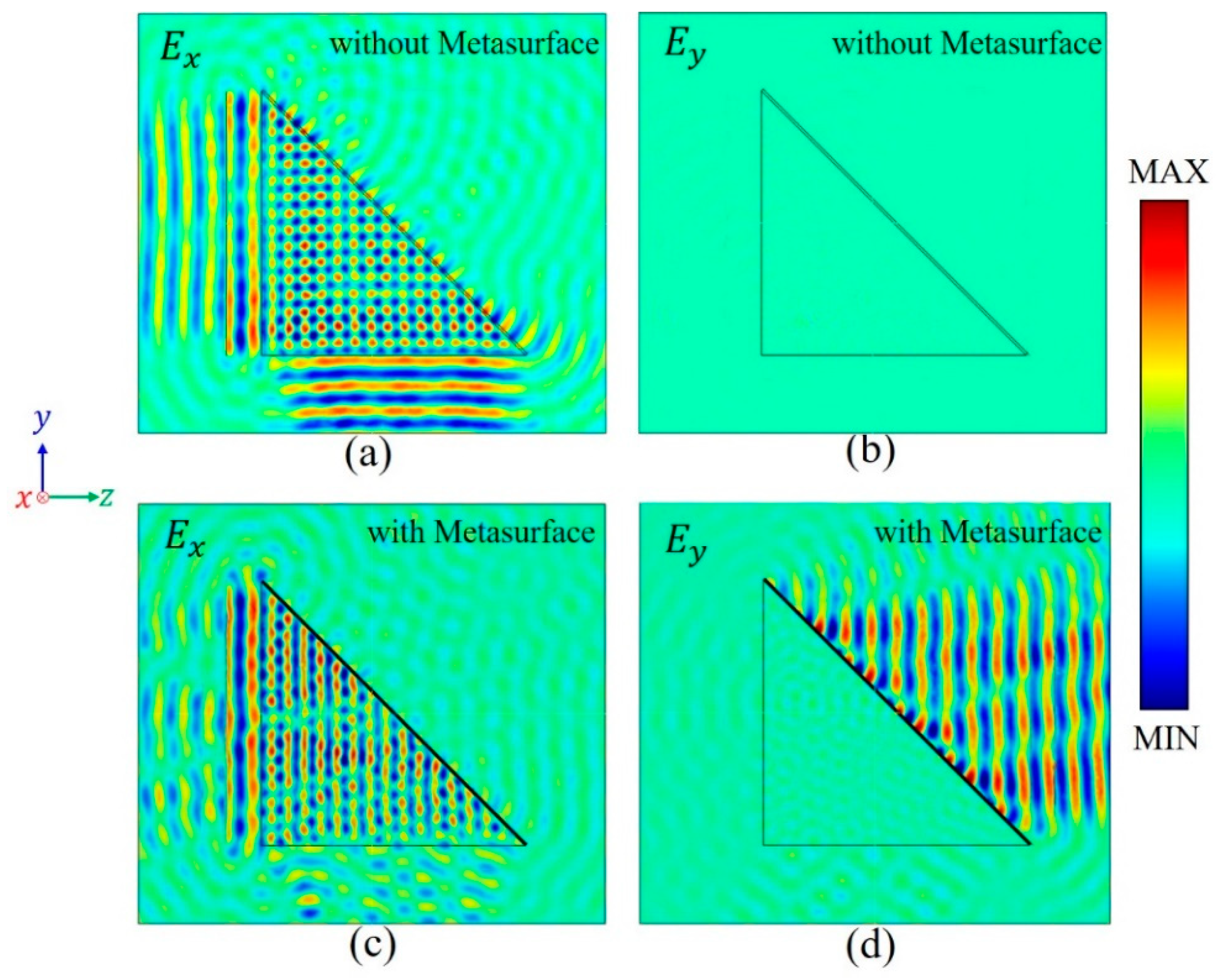
When the incident angle of an x-polarized THz wave is larger than the TIR angle of the prism, it can be totally reflected by the HDPE–-air interface, and the y-polarized wave is negligible, as shown in Figure 3a,b. Along with the TIR, an evanescent wave appears near the interface, which can be used to excite the metasurface attached to it. By manipulating the phase of the evanescent wave, part of the incident wave can pass through the interface and radiate into the air. In order to obtain two THz beams with propagation directions perpendicular to each other, as shown in Figure 1b, the phase delay caused by the metasurface on the obliqueness of the prism should compensate for the phase difference between THz waves passing through the HDPE prism and the corresponding air, which can be expressed by Equation (1),
Δ φ = ( n 1 ) × k × z
where n = 1.53 is the refractive index of HDPE, and k is the wave vector in the vacuum. The phase delay described by Equation (1) can be obtained for the y-polarized component by arranging unit cells in the metasurface attached to the prism. Thus, the y-polarized wave can pass through the interface while the x-polarized wave is reflected, as shown in Figure 3c,d. The simulated results clearly show that the THz beam splitting can be achieved using a prism combined with a metasurface. In the simulations, periodic and scattering boundary conditions were applied to the boundaries perpendicular and parallel to the x-axis, respectively.
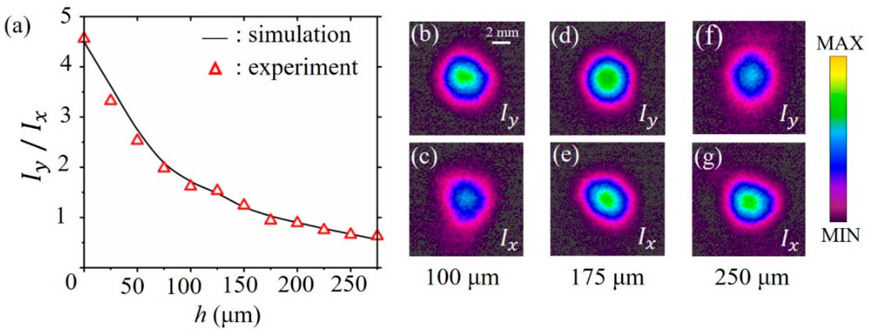
To further obtain an adjustable splitting ratio, a PI layer with a refractive index of 1.87 was inserted between the prism and the metasurface. The dependencies of both simulated and measured splitting ratios on the PI thickness are shown in Figure 4a, which agree well with each other. Iy and Ix are the intensities of the transmitted y-polarized and reflected x-polarized waves, respectively. When the PI thickness increased from 0 to 275 μm, the resonant response of the control cell was excited by the evanescent wave, which attenuates gradually, and thus the intensity ratio of the y- and x-polarized components could vary from 4.56:1 to 0.63:1. When h was in the range of 100 to 175μm, there was a small hump, which was mainly caused by the interference between the transmitted and reflected waves in the PI gap. When h = 175 μm, the simulated and measured intensity ratios were 1.03:1 and 0.94:1, respectively. When the PI thicknesses were 100, 175, and 250 μm, respectively, the measured field distributions were as shown in Figure 4b–g, which are consistent with theoretical expectations. Therefore, the splitting ratio of the proposed structure can be tuned just by varying the PI thickness while the metasurface used is the same.
The experimental setup for measuring THz beam splitting is shown in Figure 5a. The back with C-shaped structures (left) and the magnified image (right) of a fabricated metasurface sample are shown in Figure 5b. Figure 5c is the image of the front with a grating. In the experiment, an impact ionization avalanche transit-time (IMPATT) diode operating at the frequency of 0.14 THz was used as the emission source. The x-polarized output waves are collimated by a commercial lens with a focal length of 10 cm and then normally incident onto a right-angle prism with a metasurface attached. The transmitted and reflected THz waves are focused by a lens and further collected by a PYIII camera developed by Ophir, respectively. The gap width between the prism and metasurface is varied by changing the number of PI layers to realize the adjustable splitting ratio. The camera can operate over the entire THz frequency range (0.1–10 THz) with an effective area of 1.24 × 1.24 cm2 and 124 × 124 pixels with a 0.1 mm pixel interval. The power of collected THz waves can be calculated by integrating the data obtained from the camera.
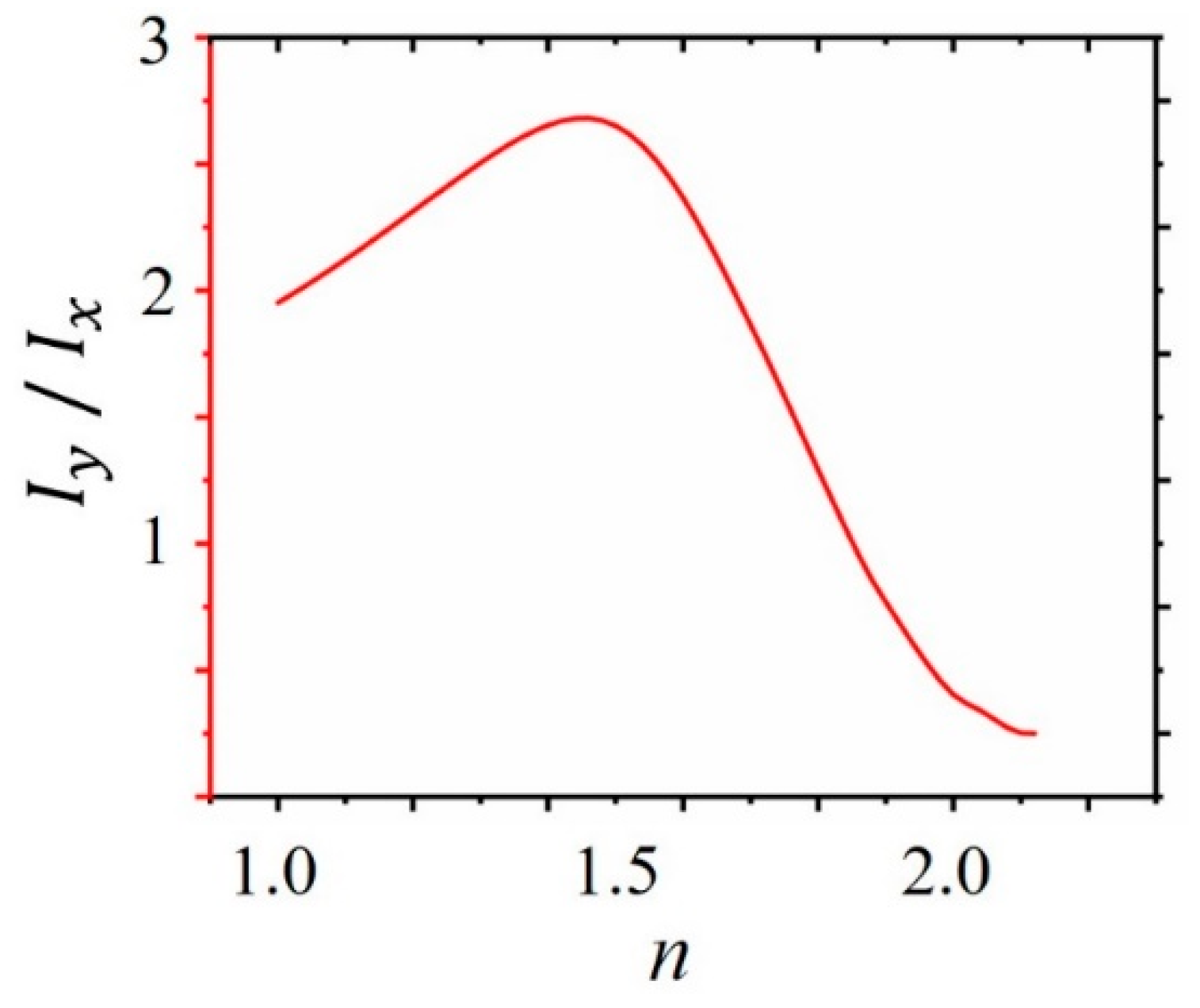
Furthermore, the splitting ratio can also be adjusted by changing the refractive index of the dielectric between the prism and metasurface. When it increases from 1 to 2.1 in Figure 6, the splitting ratio increases first and then decreases. The peak is located at n = 1.46, which slightly deviates from the refractive index of HDPE. While selecting the eight control cells in Figure 1d to obtain almost the same transmittance, the resonant responses of several cells are not at the peak, which causes the deviation.

3. Conclusions

A THz beam splitter with an adjusting splitting ratio is proposed using a metasurface integrated inon a prism. We demonstrate that the designed metasurface can convert part of the x-polarized incident waves into a y-polarized wave and control its phase simultaneously. As a result, it can pass through the beam splitter. The other part of the x-polarized wave is reflected by the prism. The splitting ratio can be tuned by varying the thickness or the refractive index of the dielectric material between the metasurface and the prism. The measured splitting ratio can be adjusted in the range between 4.56:1 and 0.63:1 by changing the dielectric thickness. Therefore, the proposed THz beam splitter has significant potential applications in 6G wireless communications, imaging, and nondestructive testing.

Author Contributions

Conceptualization, H.L.; methodology, W.Z., J.L., and H.L.; software, W.Z. and J.L.; validation, W.Z. and J.L.; formal analysis, W.Z. and H.L.; investigation, W.Z. and J.L.; resources, H.L. and Q.Q.; data curation, W.Z. and J.L.; writing—original draft preparation, W.Z.; writing—review and editing, M.Z., H.S., L.L., Q.Q., and H.L.; visualization, W.Z.; supervision, H.L.; project administration, H.L.; funding acquisition H.L. and Q.Q. All authors have read and agreed to the published version of the manuscript.

Funding

The National Natural Science Foundation of China (11874270); Natural Science Foundation of Guangdong Province, China (2022A1515011383); Fund Project for Shenzhen Fundamental Research Program (JCYJ20200109105825504, JCYJ20180305125000525).

Institutional Review Board Statement

Not applicable.

Informed Consent Statement

Not applicable.

Data Availability Statement

The data presented in this study are available on request from the corresponding author. The data are not publicly available due to restrictions.

Conflicts of Interest

The authors declare no conflict of interest.

References

  1. Tonouchi, M. Cutting-edge terahertz technology. Nat. Photon. 2007, 1, 97–105. [Google Scholar] [CrossRef]
  2. Nagatsuma, T.; Horiguchi, S.; Minamikata, Y.; Yoshimizu, Y.; Hisatake, S.; Kuwano, S.; Yoshimoto, N.; Terada, J.; Takahashi, H. Terahertz wireless communications based on photonics technologies. Opt. Express 2013, 21, 23736–23747. [Google Scholar] [CrossRef] [PubMed] [Green Version]
  3. Federici, J.F.; Schulkin, B.; Huang, F.; Gary, D.; Barat, R.; Oliveira, F.; Zimdars, D. THz imaging and sensing for security applications—Explosives, weapons and drugs. Semicond. Sci. Technol. 2005, 20, S266–S280. [Google Scholar] [CrossRef]
  4. Mittleman, D.M. Twenty years of terahertz imaging. Opt. Express 2018, 26, 9417–9431. [Google Scholar] [CrossRef] [PubMed]
  5. Tiang, C.K.; Cunningham, J.; Wood, C.; Hunter, I.C.; Davies, A.G. Electromagnetic simulation of terahertz frequency range filters for genetic sensing. J. Appl. Phys. 2006, 100, 066105. [Google Scholar] [CrossRef]
  6. Liang, J.X.; Ning, T.Y.; Fan, J.Y.; Zhang, M.; Su, H.; Zeng, Y.J.; Liang, H.W. Metallic waveguide transmitarrays for dual-band multibeam terahertz antennas. Appl. Phys. Lett. 2021, 119, 253501. [Google Scholar] [CrossRef]
  7. Fan, J.Y.; Zhang, L.; Wu, Z.Y.; Liang, J.X.; Ning, T.Y.; Zhang, M.; Su, H.; Liang, H.W. Simultaneous and independent control of phase and polarization in terahertz band for functional integration of multiple devices. Opt. Laser Technol. 2022, 151, 108064. [Google Scholar] [CrossRef]
  8. Berry, C.W.; Jarrahi, M. Broadband Terahertz Polarizing Beam Splitter on a Polymer Substrate. J. Infrared Millim. Terahertz 2011, 33, 127–130. [Google Scholar] [CrossRef]
  9. Homes, C.C.; Carr, G.L.; Lobo, R.P.S.M.; LaVeigne, J.D.; Tanner, D.B. Silicon beam splitter for far-infrared and terahertz spectroscopy. Appl. Opt. 2007, 46, 7884–7888. [Google Scholar] [CrossRef]
  10. Lai, W.; Born, N.; Schneider, L.M.; Rahimi-Iman, A.; Balzer, J.C.; Koch, M. Broadband antireflection coating for optimized terahertz beam splitters. Opt. Mater. Express 2015, 5, 2812–2819. [Google Scholar] [CrossRef]
  11. Naylor, D.A.; Boreiko, R.T.; Clark, T.A. Mylar beam-splitter efficiency in far infrared interferometers: Angle of incidence and absorption effects. Appl. Opt. 1978, 17, 1055–1058. [Google Scholar] [CrossRef] [PubMed]
  12. Kampffmeyer, G.; Pfeil, A. Self-supporting thin-film beam splitter for far-infrared interferometers. Appl. Phys. 1977, 14, 313–317. [Google Scholar] [CrossRef]
  13. Rowell, N.L.; Wang, E.A. Bilayer free-standing beam splitter for Fourier transform infrared spectrometry. Appl. Opt. 1996, 35, 2927–2933. [Google Scholar] [CrossRef] [PubMed]
  14. Chen, H.T.; Taylor, A.J.; Yu, N. A review of metasurfaces: Physics and applications. Rep. Prog. Phys. 2016, 79, 076401. [Google Scholar] [CrossRef] [Green Version]
  15. Beruete, M.; Jáuregui-López, I. Terahertz sensing based on metasurfaces. Adv. Opt. Mater. 2019, 8, 1900721. [Google Scholar] [CrossRef] [Green Version]
  16. Venkatesh, S.; Lu, X.; Saeidi, H.; Sengupta, K. A high-speed programmable and scalable terahertz holographic metasurface based on tiled CMOS chips. Nat. Electron. 2020, 3, 785–793. [Google Scholar] [CrossRef]
  17. Cong, L.; Srivastava, Y.K.; Zhang, H.; Zhang, X.; Han, J.; Singh, R. All-optical active THz metasurfaces for ultrafast polarization switching and dynamic beam splitting. Light Sci. Appl. 2018, 7, 28. [Google Scholar] [CrossRef] [Green Version]
  18. Niu, T.; Withayachumnankul, W.; Upadhyay, A.; Gutruf, P.; Abbott, D.; Bhaskaran, M.; Sriram, S.; Fumeaux, C. Terahertz reflectarray as a polarizing beam splitter. Opt. Express 2014, 22, 16148–16160. [Google Scholar] [CrossRef]
  19. Liu, S.; Cui, T.J.; Xu, Q.; Bao, D.; Du, L.; Wan, X.; Tang, W.X.; Ouyang, C.; Zhou, X.Y.; Yuan, H.; et al. Anisotropic coding metamaterials and their powerful manipulation of differently polarized terahertz waves. Light Sci. Appl. 2016, 5, e16076. [Google Scholar] [CrossRef] [Green Version]
  20. Lee, W.S.L.; Nirantar, S.; Headland, D.; Bhaskaran, M.; Sriram, S.; Fumeaux, C.; Withayachumnankul, W. Broadband Terahertz Circular-Polarization Beam Splitter. Adv. Opt. Mater. 2018, 6, 1700852. [Google Scholar] [CrossRef]
  21. Yi, H.; Qu, S.-W.; Ng, K.-B.; Wong, C.K.; Chan, C.H. Terahertz Wavefront Control on Both Sides of the Cascaded Metasurfaces. IEEE Trans. Antennas Propag. 2018, 66, 209–216. [Google Scholar] [CrossRef]
  22. Zang, X.; Gong, H.; Li, Z.; Xie, J.; Cheng, Q.; Chen, L.; Shkurinov, A.P.; Zhu, Y.; Zhuang, S. Metasurface for multi-channel terahertz beam splitters and polarization rotators. Appl. Phys. Lett. 2018, 112, 171111. [Google Scholar] [CrossRef]
  23. Wei, M.; Xu, Q.; Wang, Q.; Zhang, X.; Li, Y.; Gu, J.; Tian, Z.; Zhang, X.; Han, J.; Zhang, W. Broadband non-polarizing terahertz beam splitters with variable split ratio. Appl. Phys. Lett. 2017, 111, 071101. [Google Scholar] [CrossRef] [Green Version]
  24. Pan, W.; Wang, X.; Chen, Q.; Ren, X.; Ma, Y. Terahertz Beam Splitter Based on I-Shaped Metasurface. Prog. Electromagn. Res. M 2020, 90, 27–35. [Google Scholar] [CrossRef] [Green Version]
  25. Li, J.; Zhang, L.; Zhang, M.; Su, H.; Li, I.L.; Ruan, S.; Liang, H. Wearable Conformal Metasurfaces for Polarization Division Multiplexing. Adv. Opt. Mater. 2020, 8, 2000068. [Google Scholar] [CrossRef]
  26. Ginzburg, P.; Fortuno, F.J.R.; Wurtz, G.A.; Dickson, W.; Murphy, A.; Morgan, F.; Pollard, R.J.; Iorsh, I.; Atrashchenko, A.; Belov, P.A.; et al. Manipulating polarization of light with ultrathin epsilon-near-zero metamaterials. Opt. Express 2013, 21, 14907–14917. [Google Scholar] [CrossRef]
  27. Monticone, F.; Estakhri, N.M.; Alù, A. Full Control of Nanoscale Optical Transmission with a Composite Metascreen. Phys. Rev. Lett. 2013, 110, 203903. [Google Scholar] [CrossRef]
  28. Ordal, M.A.; Long, L.L.; Bell, R.J.; Bell, S.E.; Bell, R.R.; Alexander, R.W.; Ward, C.A. Optical properties of the metals Al, Co, Cu, Au, Fe, Pb, Ni, Pd, Pt, Ag, Ti, and W in the infrared and far infrared. Appl. Opt. 1983, 22, 1099–1119. [Google Scholar] [CrossRef]
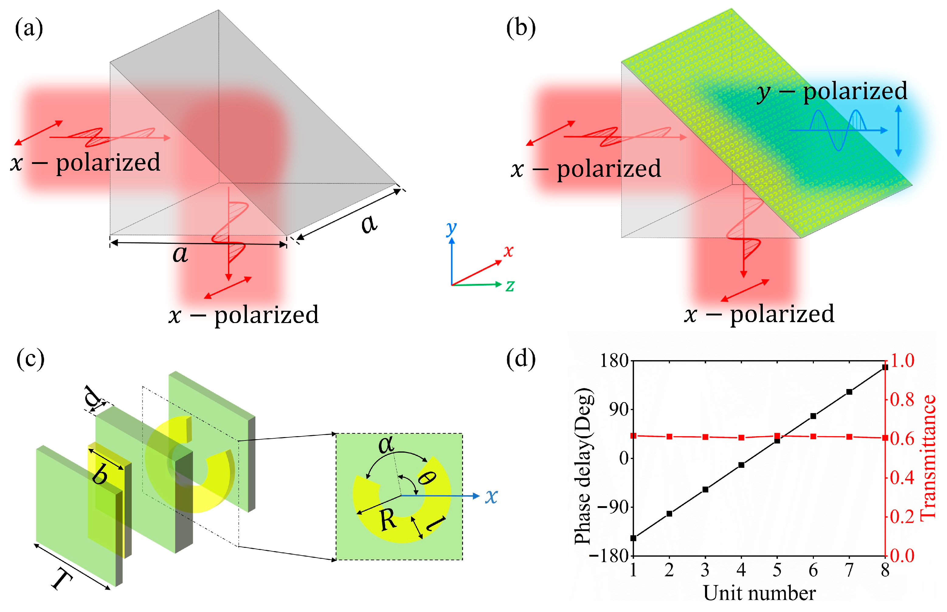
Figure 1. Schematic of an HDPE prism (a) Without and (b) With a metasurface attached for the control of THz beams. (c) Structure of a unit cell in the metasurface. (d) Phase delay and transmittance of selected eight cells for b = 0.4 mm, R = 0.34 mm, and T = 0.8 mm. The target frequency is f = 0.14 THz.
Photonics 10 00118 g001
Figure 2. Transmittance (ac) and phase delay (df) as functions of the opening size α, and opening direction θ for the outer radius R = 0.34 mm.
Photonics 10 00118 g002
Figure 3. Simulated THz wave propagation controlled by a prism (a,b) Without and (c,d) With a metasurface attached.
Photonics 10 00118 g003
Figure 4. (a) Simulated and measured splitting ratios as functions of the PI thickness. (bg) Measured field distributions of y- and x-polarized components for h = 100, 175, and 250 μm, respectively.
Photonics 10 00118 g004
Figure 5. (a) Schematic of the experimental setup. (b) The black with C-shaped structures (left) and the magnified image (right) of a fabricated metasurface sample. (c) Image of the front with a grating.
Photonics 10 00118 g005
Figure 6. Dependence of the splitting ratio on the refractive index of the dielectric in the gap for h = 150 μm.
Photonics 10 00118 g006
Disclaimer/Publisher’s Note: The statements, opinions and data contained in all publications are solely those of the individual author(s) and contributor(s) and not of MDPI and/or the editor(s). MDPI and/or the editor(s) disclaim responsibility for any injury to people or property resulting from any ideas, methods, instructions or products referred to in the content.