Fast and Accurate Measurement of Hole Systems in Curved Surfaces
Abstract
1. Introduction
2. Theoretical Fundamentals
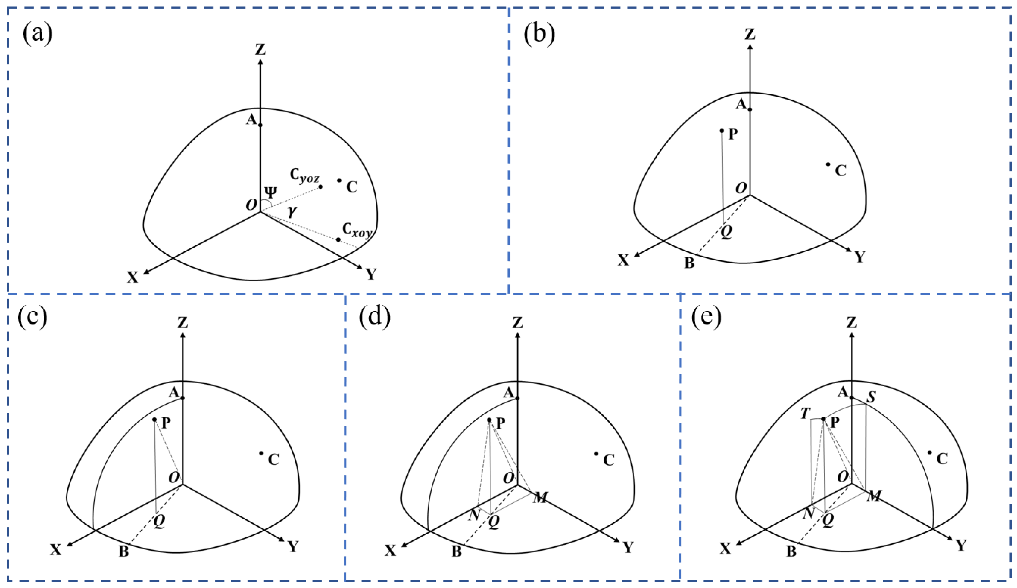
- Draw a line PQ perpendicular to the coordinate plane XY at point Q. Additionally, draw a line OB through point Q intersecting a large arc on coordinate plane XY at point B, as shown in Figure 1b;
- As shown in Figure 1c, draw a large arc AB passing through plane OAB, and point P must be on large arc AB and OP = R;
- As shown in Figure 1d, draw a line QM perpendicular to the Y axis at point M and a straight line QN perpendicular to the X axis at point N;
- Draw a line MS parallel to the Z axis, intersecting the large arc on the coordinate plane YZ at point S, and then the small arc of the plane PQMS on the sphere is PS;
- Draw a line NT parallel to the Z axis, intersecting the large arc on the coordinate plane XZ at point T, and the small of the plane PQNT arc on the sphere is PT, as shown in Figure 1e.
3. Measurement Scheme and Error Analysis of the Holes in a Spherical Surface
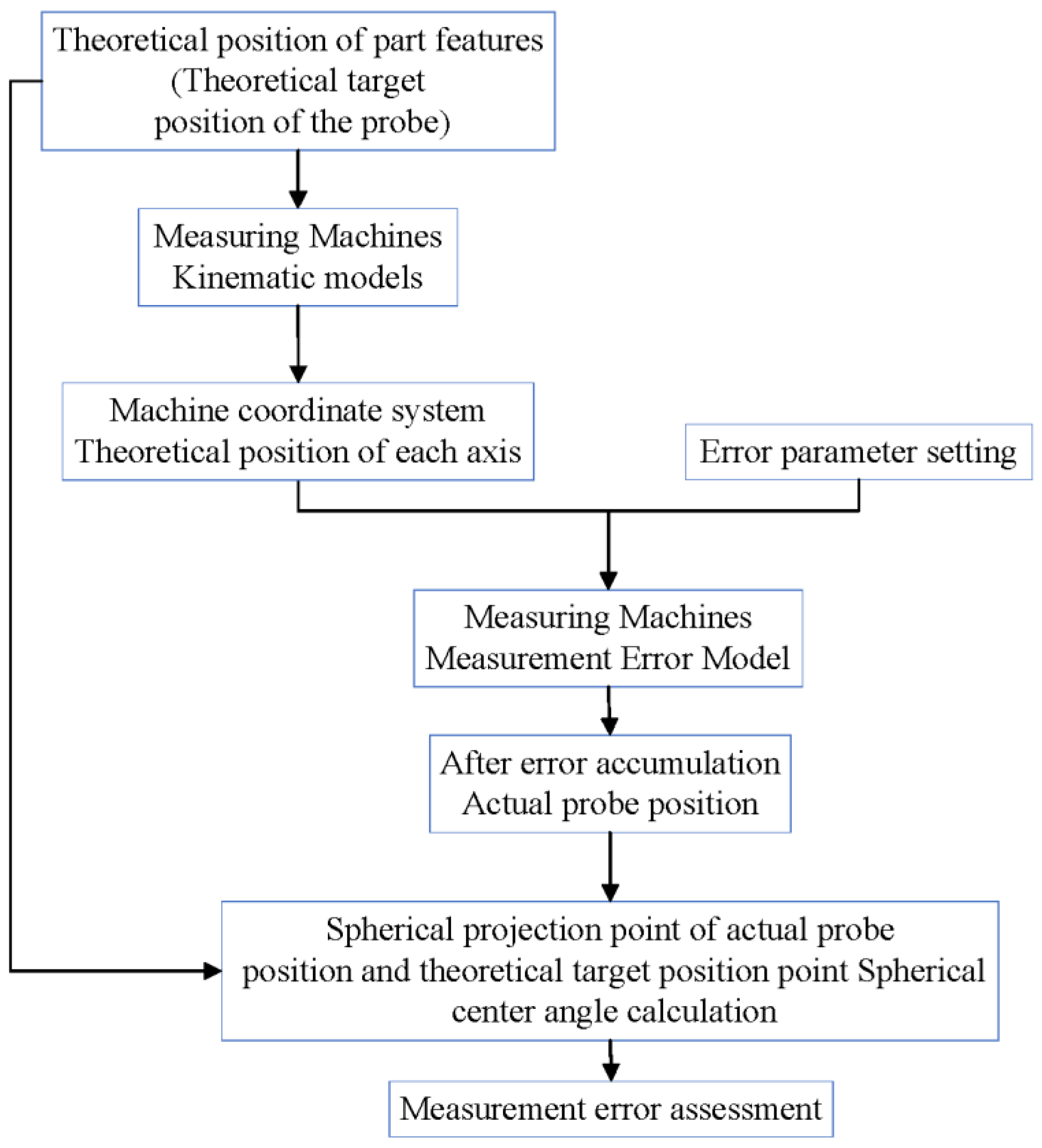
3.1. Overall Measurement Scheme
3.2. Measurement Error Analysis and Shafting Optimization
- (1)
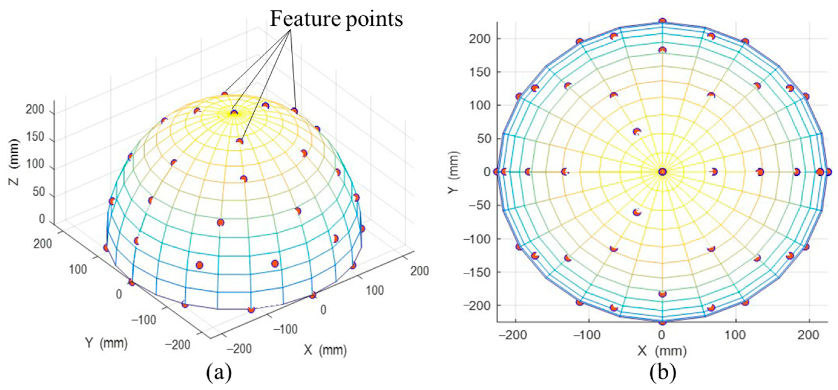
- The position distribution model for detecting features
- (2)
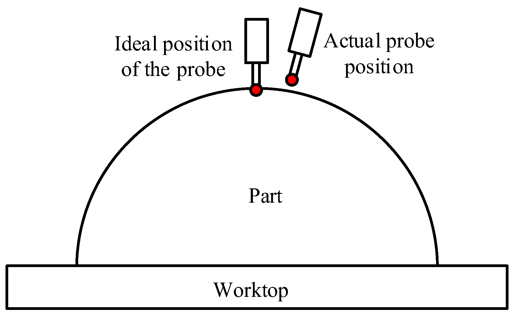
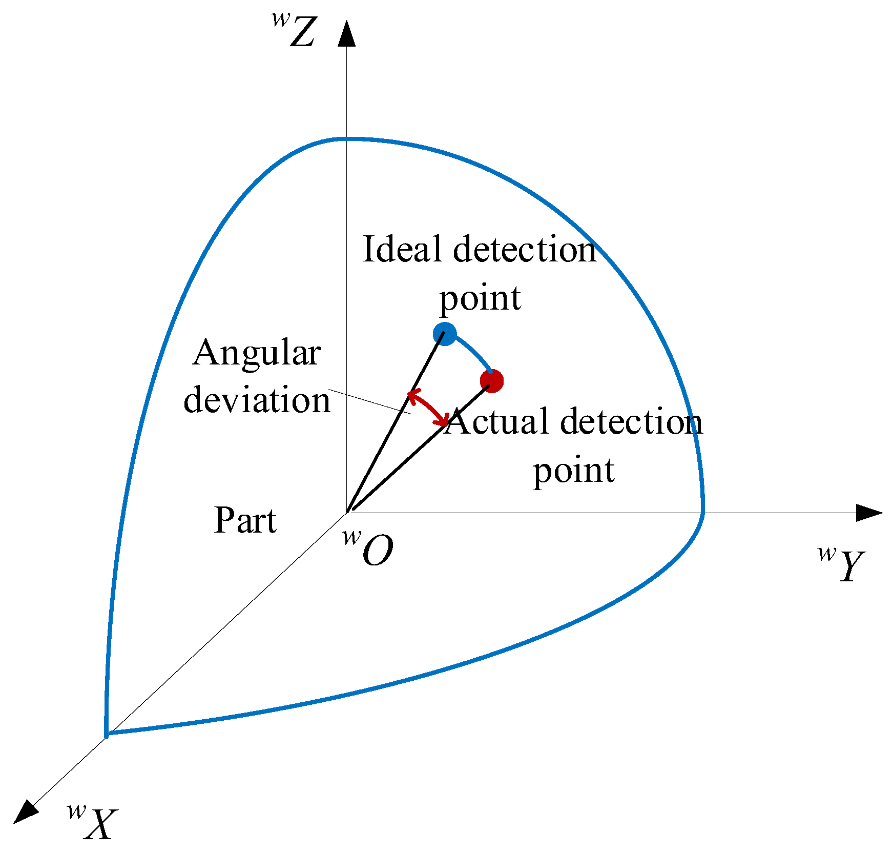
- Evaluation method of measurement error
3.3. Accuracy Allocation of the Measurement Machine
- (1)
- Geometric error allocation of measuring machines
- (2)
- Allocation of measurement accuracy for optical probes
- (3)
- Comprehensive measurement accuracy analysis
4. Measurement System and Testing
4.1. Establishing an Optical Measurement Coordinate System
4.2. Spherical Hole Positioning Based on the Machine Vision Algorithm
- (1)
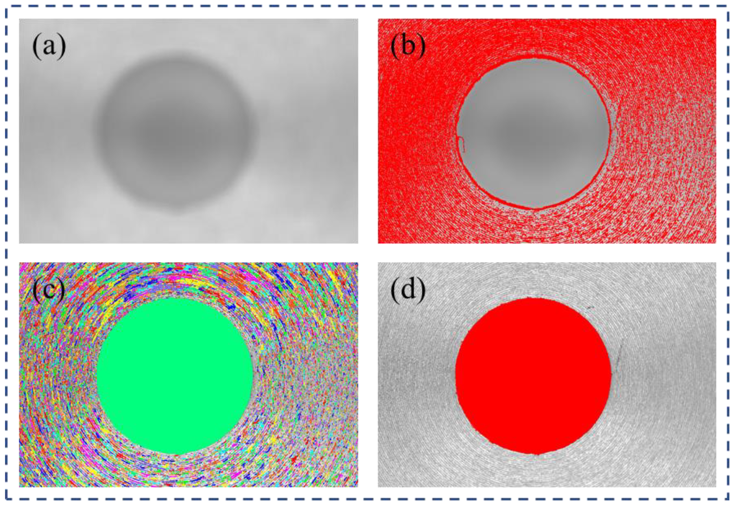
- Firstly, we performed mean filtering on the original image to obtain a smoothed reference image , as shown in Figure 12a.
- (2)
- Subsequently, we extracted the darker portions of the original image concerning the reference image using Equation (22), denoting the foreground (region of the blind hole) and the background (area outside the hole). The results of the local threshold segmentation are illustrated in Figure 12b.where “foreground” represents the region of the blind hole, “background” represents the background area outside the hole, denotes the pixel value at coordinates in the original image, represents the pixel value at coordinates in the reference image, and the parameter is chosen based on engineering experience. A larger value results in a smaller extracted region.
- (3)
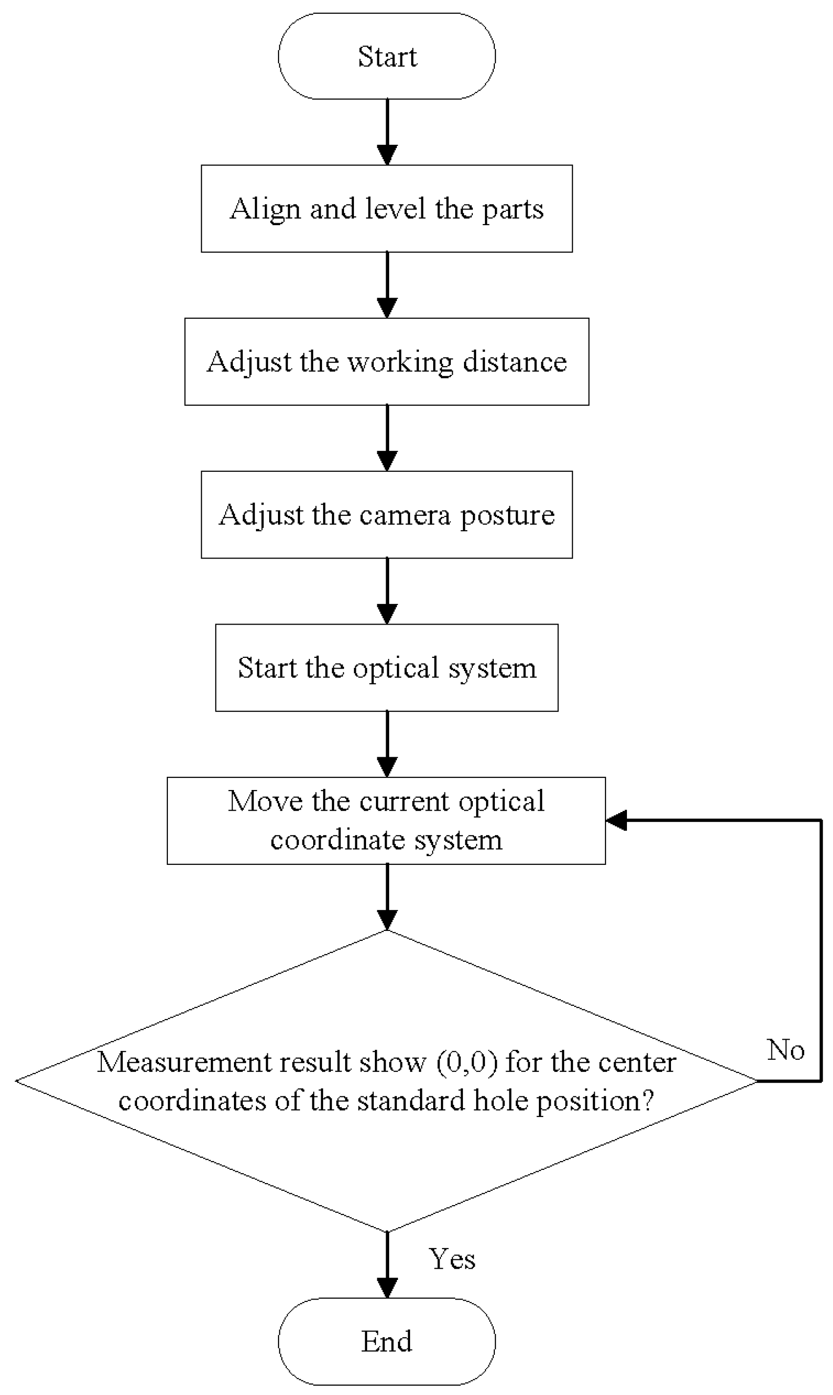
4.3. Measurement Process
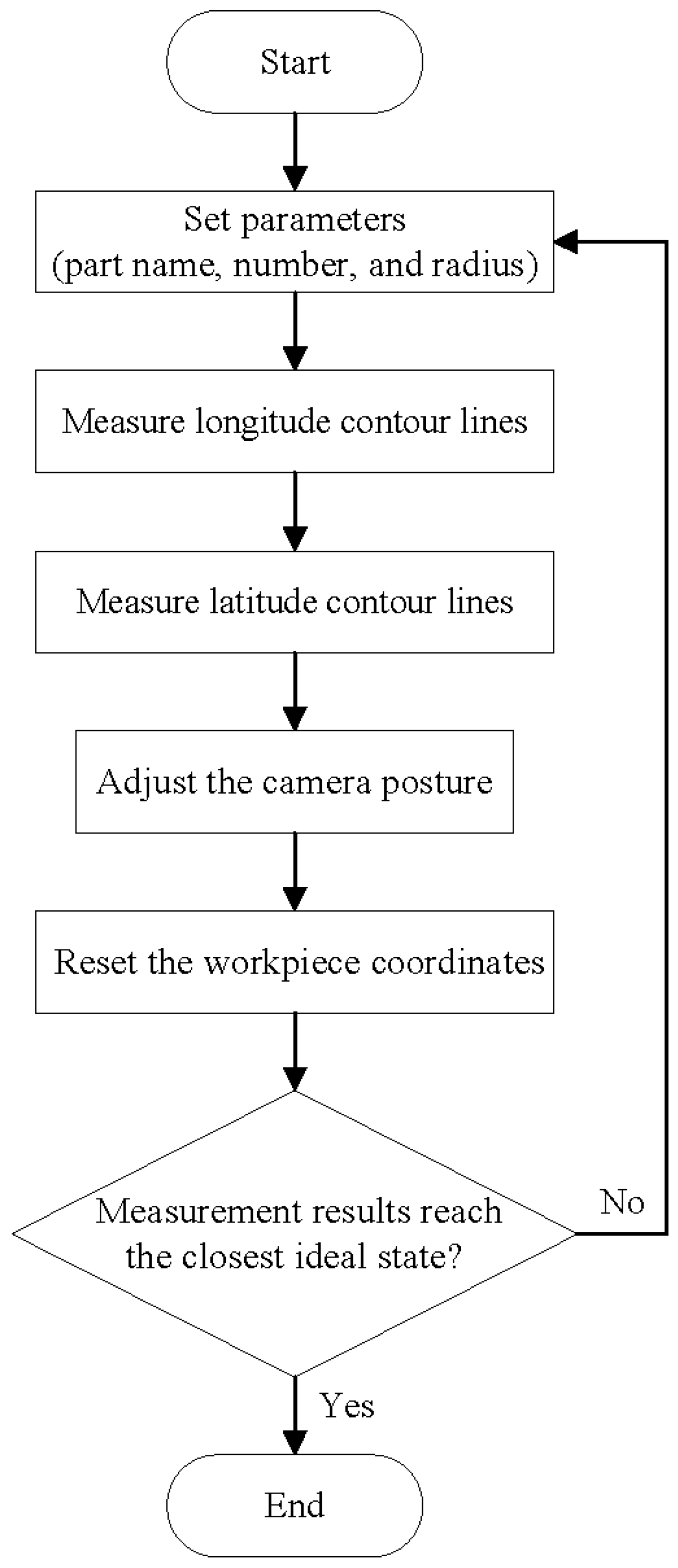
- Set part parameters, including part name, part number, and part radius.
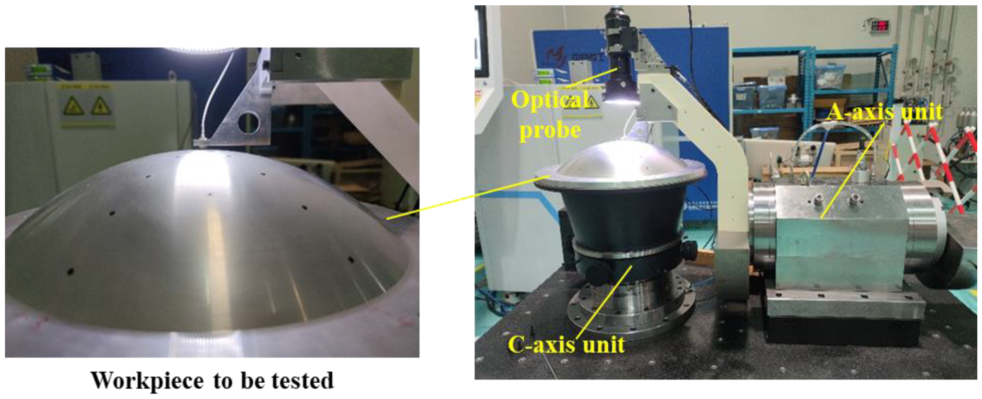
- Use high-precision displacement sensors to measure the longitude contour, rotate the C-axis, and set the measurement range to 0~360°. After the measurement is completed, the collected contour lines will automatically be displayed in the longitude curve-drawing coordinate system. If the workpiece alignment is completed, the theoretical measurement result should be a straight line.
- Use high-precision displacement sensors to measure the latitude contour, rotate the A-axis, and set the measurement range to −50~50°. After the measurement is completed, the collected contour lines will automatically be displayed in the latitude curve-drawing coordinate system. If the workpiece leveling is completed, the theoretical measurement result should be a straight line.Due to the possibility of passing through hole positions on the workpiece surface and introducing other errors during the measurement of longitude and latitude contours, the quality of the measured curves may deteriorate. Therefore, a curve fitting function is provided to obtain ideal contour lines.
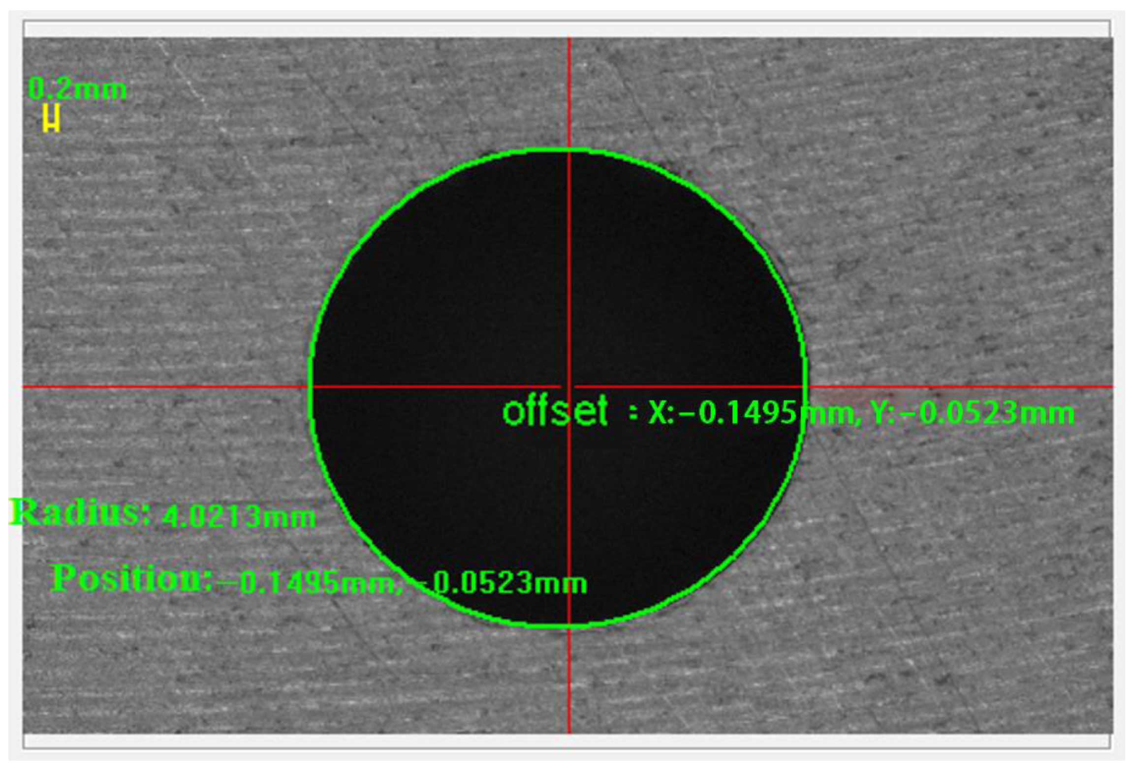
- Adjust the camera posture so that the center coordinates of the standard hole position of the workpiece coincide with the coordinate system “cross line” as much as possible.
- After adjusting the pose of the workpiece and camera, click the “Set WCS” button to reset the workpiece coordinates of the current C-axis and A-axis to zero, and set them as the starting point for measurement, which is the measurement programming reference.
4.4. Measurement Result
5. Conclusions
Author Contributions
Funding
Data Availability Statement
Conflicts of Interest
References
- Tang, J.; Xu, X.; Zhou, G. A survey of measurement methods of the machine vision hole series coordinates on curved surface. J. Mach. 2006, 11, 3–5. (In Chinese) [Google Scholar]
- Zhu, J.; Xu, X.; Wang, Y. Study on non-contacting measurement system for position of hole series by image processing. J. Electr. Autom. 2006, 28, 58–59. (In Chinese) [Google Scholar]
- Huang, J.; Zhou, Z.; Deng, J.; Li J., G. High precision method to detect serial hole center coordinate based on circle fitting. J. Tool Eng. 2004, 4, 47–49. (In Chinese) [Google Scholar]
- Huang, J.; Zhou, Z.; Yu, L. A precision measurement system based on linear array CCD used for hole series on curved surface. J. Opto-Electron. Eng. 2003, 4, 39–41. (In Chinese) [Google Scholar]
- Yu, Z. Research on the Noncontact Measurement System of Spherical Circular Hole Series. Master’s Thesis, Sichuan University, Chengdu, China, 18 April 2003. [Google Scholar]
- Deng, J. The Measurement System of Spherical Circular Hole Series Basing on Machine Vision. Master’s Thesis, Sichuan University, Chengdu, China, 20 April 2004. [Google Scholar]
- Huang, J. Study on the Machine Vision Measure System for Position of Hole Series on Curved Surface. Ph.D. Thesis, Sichuan University, Chengdu, China, 8 April 2004. [Google Scholar]
- Zhang, C.; Zhao, Z. Rapidly measuring system for ectopic holes based on laser displacement detection. J. Mach. Build. Autom. 2018, 47, 216–219. (In Chinese) [Google Scholar]
- Xu, X. Study on the Fast and Precise Machine Vision System for the Hole-Positions on the Sphere Surface. Ph.D. Thesis, Sichuan University, Chengdu, China, 10 May 2006. [Google Scholar]
- Sun, W.; Yi, J.; Ma, G. A vision-based method for dimensional in situ measurement of cooling holes in aero-engines during laser beam drilling process. J. Int. J. Adv. Manuf. Technol. 2022, 119, 3265–3277. [Google Scholar] [CrossRef]
- Chen, X.; Longstaff, A.; Fletcher, S.; Myers, A. Analyzing and evaluating a dual-sensor autofocusing method for measuring the position of patterns of small holes on complex curved surfaces. J. Sens. Actuators A-Phys. 2014, 210, 86–94. [Google Scholar] [CrossRef]
- Xu, S.; Huang, J.; Wang, D. Location measurement of holes on the spheroid part based on VC++ and Matlab. J. Ordnance Ind. Autom. 2005, 2, 31–32. (In Chinese) [Google Scholar]
- Long, J. A device and Its Usage Method for Measuring the Accuracy of Centripetal Focusing Hole System. China Patent CN110006346A, 12 July 2019. [Google Scholar]
- Chen, X.; Andrew, L.; Simon, F.; Myers, A. Deployment and evaluation of a dual-sensor autofocusing method for on-machine measurement of patterns of small holes on freeform surfaces. J. Appl. Opt. 2014, 53, 2246–2255. [Google Scholar] [CrossRef] [PubMed][Green Version]
- Li, M. The practice of the method used in measuring the location degree of the hole department by three coordinates. J. Metrol. Meas. Tech. 2008, 35, 27–28. (In Chinese) [Google Scholar]
- Huang, F.; Yu, T.; Zhang, R. A new method for measuring the position error of hole system. J. Agric. Mech. Res. 2004, 4, 170–171. (In Chinese) [Google Scholar]
- Huang, J.; Xu, B. A machine vision system for position measurement of small holes on the spherical surface. J. Nanotechnol. Precis. Eng. 2016, 14, 28–34. [Google Scholar]
- Xie, S. Angle measurement of the large circular hole system. J. Metrol. Meas. Tech. 1996, 2, 5–7. (In Chinese) [Google Scholar]
- Luo, T. The precision analysis of the measuring method for the holes centers distance in the workshop. J. Mech. Res. Appl. 2005, 4, 30–31. (In Chinese) [Google Scholar]
- He, G.; Huang, X.; Guo, L.; Sang Y., C.; Huang, C. A Method for Detecting and Evaluating the Composite Positional Error of The Spherical Hole System. China Patent CN106568365A, 05 March 2019. [Google Scholar]
- Wang, Y.; Ren, G.; Wu, B. Measuring the coaxiality of the hole system using a coordinate measuring machine. J. Mod. Manuf. Technol. Equip. 2000, 1, 39–40. (In Chinese) [Google Scholar]
- Yu, H.; Zhao, Z.; Lu, Y. A Measurement System and Method for Coaxiality Error of a Reference-Free Hole System. China Patent CN104316001A, 28 January 2015. [Google Scholar]
- Wu, E. Discussion on measuring tools of hole system in irregular-shaped parts. J. Met. Work. Met. Cut. 2008, 17, 49–51. (In Chinese) [Google Scholar]
- Xu, K. The Key Technology Research of Multifunctional Probe about Big Distance of Porous Parts. Master’s Thesis, Nanjing University of Aeronautics and Astronautics, Nanjing, China, March 2014. [Google Scholar]
- Xu, B. Research on the Application of Surface Array CCD in Measuring the Coaxiality of the Hole System. Master’s Thesis, Tianjin University, Tianjin, China, 1999. [Google Scholar]
- Bieman, L. A novel method for spatial measurement of holes. J. SPIE Opt. Illum. Image Sens. Mach. Vis. 1987, 728, 116–122. [Google Scholar]
- Gong, Y.; Seibel, E. Three-dimensional measurement of small inner surface profiles using feature-based 3-D panoramic registration. J. Opt. Eng. 2017, 56, 014108. [Google Scholar] [CrossRef]
- Liu, Z. Research of Holes Position Measurement Method on a Curved Surface Based on Computer Vision. Master’s Thesis, Huaqiao University, Quanzhou, China, 28 March 2014. [Google Scholar]
- Gorpas, D.; Politopoulos, K.; Yova, D. A binocular machine vision system for three-dimensional surface measurement of small objects. J. Comput. Med. Imaging Graph. 2007, 31, 625–637. [Google Scholar] [CrossRef] [PubMed]
- Malassiotis, S.; Strintzis, M. Stereo vision system for precision dimensional inspection of 3D holes. J. Mach. Vis. Appl. 2003, 15, 101–113. [Google Scholar] [CrossRef]
- Zeng, Z.; Zhu, X.; Wang, J.; Li, X.; Lin, D. Effective area measurement of cartridges flash holes based on a machine vision system. J. Mech. Sci. Technol. Aerosp. Eng. 2016, 35, 40–43. [Google Scholar]
- Gou, J.; Chen, X.; Ye, N.; Zhang L., Y. Development of on-machine vision inspection system for connection holes on aircraft parts. J. Aeronaut. Manuf. Technol. 2018, 61, 37–43. (In Chinese) [Google Scholar]
- Fang, Z.; McGlure, V. Precision noncontact measurement of blind holes by machine vision technology. J. SPIE Autom. Insp. Nov. Instrum. 1997, 3185, 125–131. [Google Scholar]
- Yang, W. The Application Research of Non-Contact Measurement for the Position of the Hole in a Spherical Surface and Digital Image Processing Technology. Master’s Thesis, Sichuan University, Chengdu, China, 8 May 2004. [Google Scholar]
- Kong, L. Development of Five-Axis Additive and Subtractive Hybrid Machining Center and Research on its Processing Technology. Master’s Thesis, Xiamen University, Xiamen, China, June 2020. [Google Scholar]
- Li, C.D. Research on the Identification Method of Geometric Error of Cradle Five-Axis NC Machine Tool. Master’s Thesis, Harbin University of Science and Technology, Harbin, China, April 2020. [Google Scholar]
- Yu, Z.Q. Research on Key Technologies of a Compound Measurement System Based on Multi-Sensor Information Fusion. Ph.D. Thesis, Tianjin University, Tianjin, China, December 2019. [Google Scholar]
- Li, Z.T. Research on Online Inspection Technology of Robot Automatic Drilling Based on Vision. Master’s Thesis, Harbin University of Science and Technology, Harbin, China, March 2021. [Google Scholar]


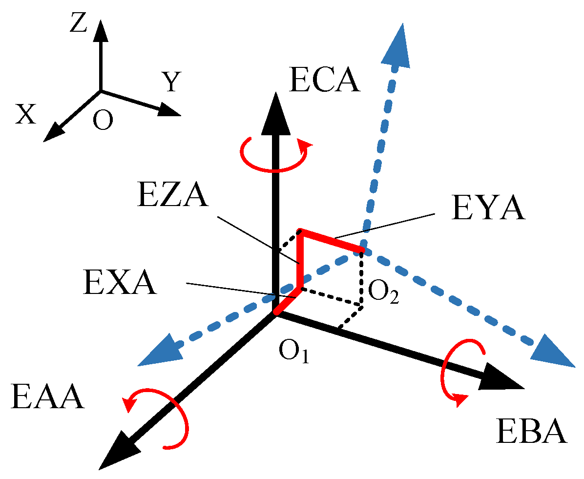
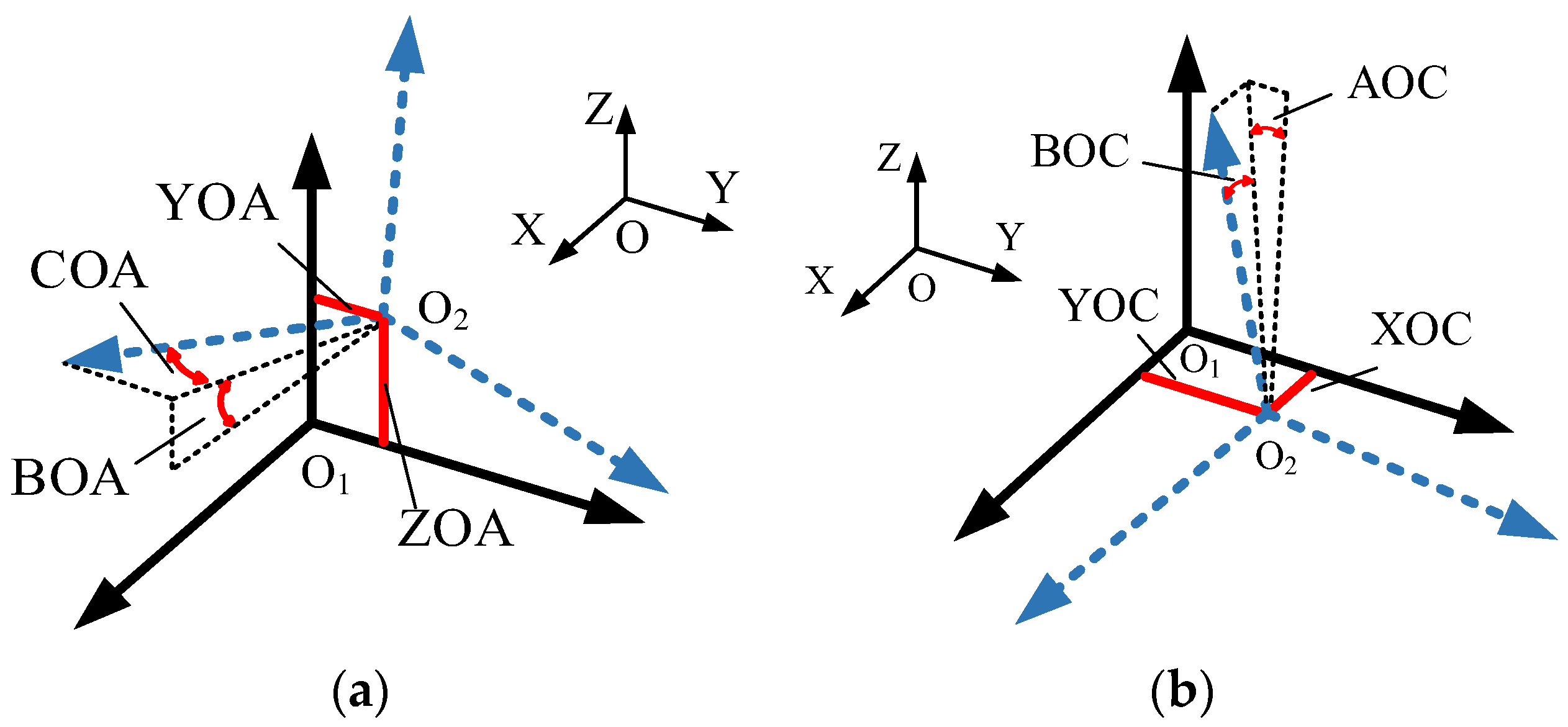

| Number | Component | Meaning of Component |
|---|---|---|
| 1 | EXA | A-Axis X-Direction Position Error |
| 2 | EYA | A-Axis Y-Direction Position Error |
| 3 | EZA | A-Axis Z-Direction Position Error |
| 4 | EAA | A-Axis Angular Positioning Error |
| 5 | EBA | A-Axis Angular Error around the Y Direction |
| 6 | ECA | A-Axis Angular Error around the Z Direction |
| 7 | EXC | C-Axis X-Direction Position Error |
| 8 | EYC | C-Axis Y-Direction Position Error |
| 9 | EZC | C-Axis Z-Direction Position Error |
| 10 | EAC | C-Axis Angular Error around the X Direction |
| 11 | EBC | C-Axis Angular Error around the Y Direction |
| 12 | ECC | C Axis Angular Positioning Error |
| 13 | BOA | Parallelism of the A-Axis with the XZ Plane |
| 14 | COA | Parallelism of the A-Axis with the XY Plane |
| 15 | YOA | Eccentricity of the A-Axis in the Y Direction |
| 16 | ZOA | Eccentricity of the A-Axis in the Z Direction |
| 17 | AOC | Parallelism of the C-Axis with the YZ Plane |
| 18 | BOC | Parallelism of the C-Axis with the XZ Plane |
| 19 | XOC | Eccentricity of the C-Axis in the X Direction |
| 20 | YOC | Eccentricity of the C-Axis in the Y Direction |
| 21 | EXW | Workpiece Clamping X-Direction Position Error |
| 22 | EYW | Workpiece Clamping Y-Direction Position Error |
| 23 | EZW | Workpiece Clamping Z-Direction Position Error |
| 24 | EAW | Workpiece Clamping Angular Deviation around the X Direction |
| 25 | EBW | Workpiece Clamping Angular Deviation around the Y Direction |
| 26 | ECW | Workpiece Clamping Angular Deviation around the Z Direction |
| Index | Precision Distribution |
|---|---|
| Stroke of axis A | ±90° |
| Rotation error of axis A | 1 μm |
| End tripping of axis A | 1 μm |
| Angular runout of axis A | 1.5 μm/300 mm(5 × 10⁻⁶ rad) |
| Rotation error of axis C | 30 nm |
| End tripping of axis A | 30 nm |
| Angular runout of axis C | 1.5 μm/300 mm(5 × 10⁻⁶ rad) |
| Installation parallelism of axis A | 3 μm/300 mm(1 × 10⁻⁵ rad) |
| Installation translation deviation of axis A | 3 μm |
| Installation parallelism of axis C | 3 μm/300 mm(1 × 10⁻⁵ rad) |
| Part clamping angle deviation | 3.5 × 10⁻⁵ rad |
| Part clamping position translational deviation | 10 μm |
| Number | Component | Average Measurement Error | Maximum Measurement Error |
|---|---|---|---|
| 1 | EXA | 0.0305 | 0.0317 |
| 2 | EYA | 0.0211 | 0.0332 |
| 3 | EZA | 0.0162 | 0.0291 |
| 4 | EAA | 0.0515 | 0.0757 |
| 5 | EBA | 0.1812 | 0.2117 |
| 6 | ECA | 0.1064 | 0.1553 |
| 7 | EXC | 7.66 × 10⁻⁴ | 0.0036 |
| 8 | EYC | 8.92 × 10⁻⁴ | 0.0029 |
| 9 | EZC | 7.89 × 10⁻⁴ | 0.0026 |
| 10 | EAC | 0.0231 | 0.0397 |
| 11 | EBC | 0.0236 | 0.0397 |
| 12 | ECC | 0.0582 | 0.0743 |
| 13 | BOA | 0.0338 | 0.0776 |
| 14 | COA | 0.0602 | 0.0787 |
| 15 | YOA | 0.1269 | 0.1283 |
| 16 | ZOA | 0.1273 | 0.1293 |
| 17 | AOC | 0 | 0 |
| 18 | BOC | 0 | 0 |
| 19 | XOC | 0 | 0 |
| 20 | YOC | 0 | 0 |
| 21 | EXW | 0.162 | 0.269 |
| 22 | EYW | 0.165 | 0.269 |
| 23 | EZW | 0.210 | 0.267 |
| 24 | EAW | 0.113 | 0.155 |
| 25 | EBW | 0.121 | 0.155 |
| 26 | ECW | 0.120 | 0.153 |
| Items Tested | Detection Results of the Three-Coordinate Machine (′) | |||||
|---|---|---|---|---|---|---|
| Linear 1 (Longitude 0°) | Linear 2 (Longitude 60°) | Linear 3 (Longitude 120°) | Linear 4 (Longitude 180°) | Linear 5 (Longitude 240°) | Linear 6 (Longitude 300°) | |
| Group 1: 6–10° ± 0.01° (latitude 10°) | 0.12 | 0.06 | 0.06 | 0.12 | 0 | 0 |
| Group 2: 6–10° ± 0.01° (latitude 20°) | −0.36 | 0.06 | −0.06 | −0.54 | −0.18 | −0.12 |
| Group 3: 6–10° ± 0.01° (latitude 30°) | −0.3 | 0.12 | 0 | −0.42 | −0.06 | 0 |
| Group 4: 6–10° ± 0.01° (latitude 40°) | −0.18 | 0.18 | −0.06 | −0.36 | 0.06 | 0 |
| Items Tested | Average of Five Angle Measurement Errors (′) | |||||
|---|---|---|---|---|---|---|
| Linear 1 (Longitude 0°) | Linear 2 (Longitude 60°) | Linear 3 (Longitude 120°) | Linear 4 (Longitude 180°) | Linear 5 (Longitude 240°) | Linear 6 (Longitude 300°) | |
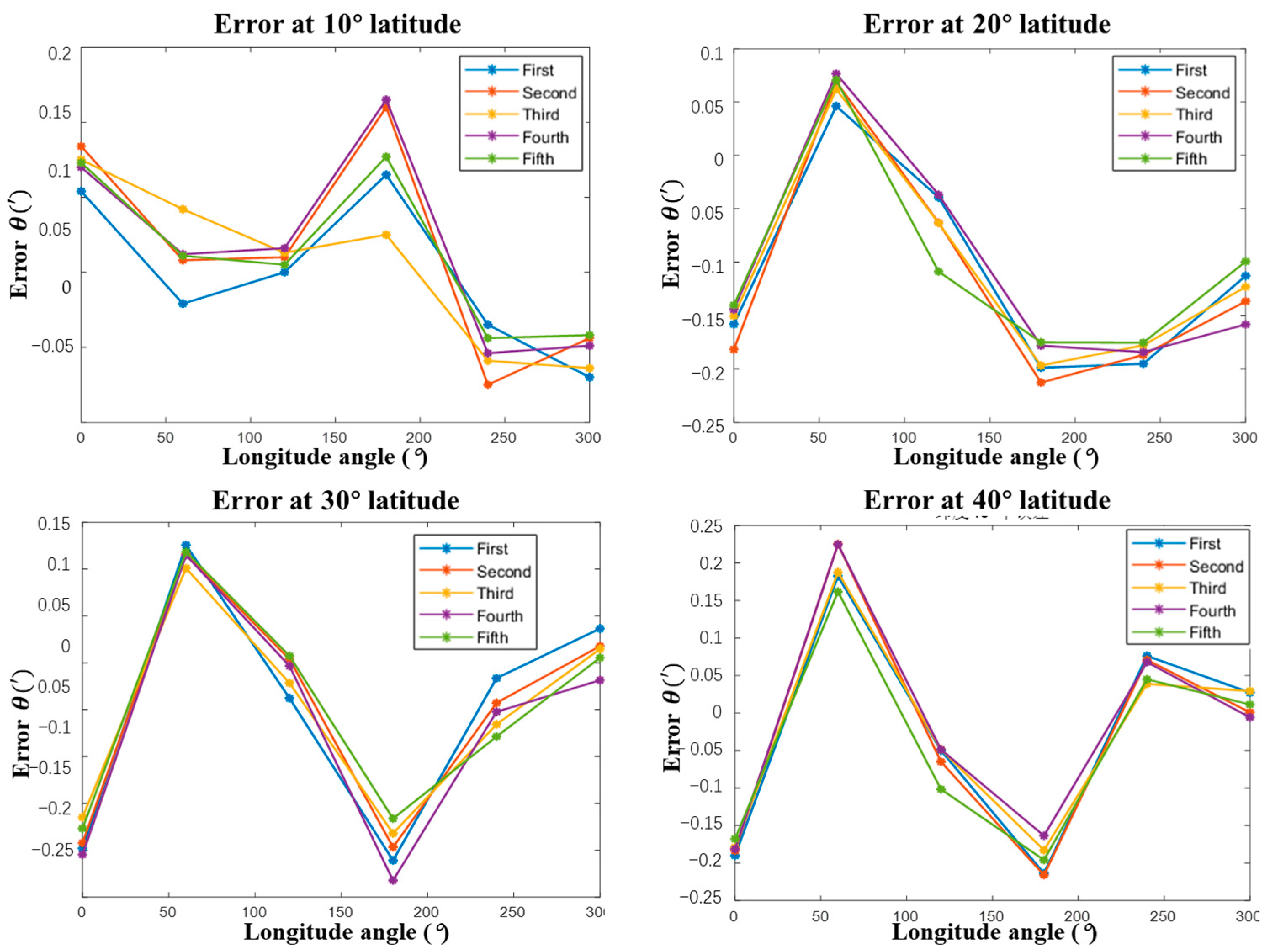
| Group 1: 6–10° ± 0.01° (latitude 10°) | 0.121 | 0.06 | 0.059 | 0.128 | −0.003 | −0.004 |
| Group 2: 6–10° ± 0.01° (latitude 20°) | −0.155 | 0.065 | −0.062 | −0.192 | −0.184 | −0.126 |
| Group 3: 6–10° ± 0.01° (latitude 30°) | −0.187 | 0.115 | −0.01 | −0.198 | −0.051 | 0.011 |
| Group 4: 6–10° ± 0.01° (latitude 40°) | −0.18 | 0.197 | −0.063 | −0.194 | 0.06 | 0.013 |
| Items Tested | Uncertainty of Five Angular Measurement Errors (′′) | |||||
|---|---|---|---|---|---|---|
| Linear 1 (Longitude 0°) | Linear 2 (Longitude 60°) | Linear 3 (Longitude 120°) | Linear 4 (Longitude 180°) | Linear 5 (Longitude 240°) | Linear 6 (Longitude 300°) | |
| Group 1: 6–10° ± 0.01° (latitude 10°) | 8.15 | 7.95 | 8.03 | 8.06 | 8.01 | 7.93 |
| Group 2: 6–10° ± 0.01° (latitude 20°) | 8.01 | 8.05 | 8.01 | 7.91 | 7.95 | 8.14 |
| Group 3: 6–10° ± 0.01° (latitude 30°) | 8.03 | 7.97 | 7.89 | 7.93 | 8.07 | 7.91 |
| Group 4: 6–10° ± 0.01° (latitude 40°) | 8.09 | 7.70 | 7.79 | 8.02 | 8.22 | 7.94 |
| Items Tested | Measured Value of This Device—Measured Value of Three Coordinates Machine (′) | |||||
|---|---|---|---|---|---|---|
| Linear 1 (longitude 0°) | Linear 2 (longitude 60°) | Linear 3 (longitude 120°) | Linear 4 (longitude 180°) | Linear 5 (longitude 240°) | Linear 6 (longitude 300°) | |
| Group 1: 6–10° ± 0.01° (latitude 10°) | 0.001 | 0 | −0.001 | 0.008 | −0.003 | −0.004 |
| Group 2: 6–10° ± 0.01° (latitude 20°) | 0.205 | 0.005 | −0.002 | 0.348 | −0.004 | −0.006 |
| Group 3: 6–10° ± 0.01° (latitude 30°) | 0.113 | −0.005 | −0.01 | 0.222 | 0.009 | 0.011 |
| Group 4: 6–10° ± 0.01° (latitude 40°) | 0 | 0.017 | −0.003 | 0.166 | 0 | 0.013 |
Disclaimer/Publisher’s Note: The statements, opinions and data contained in all publications are solely those of the individual author(s) and contributor(s) and not of MDPI and/or the editor(s). MDPI and/or the editor(s) disclaim responsibility for any injury to people or property resulting from any ideas, methods, instructions or products referred to in the content. |
© 2023 by the authors. Licensee MDPI, Basel, Switzerland. This article is an open access article distributed under the terms and conditions of the Creative Commons Attribution (CC BY) license (https://creativecommons.org/licenses/by/4.0/).
Share and Cite
Wang, P.; Kong, L.; An, H.; Gao, M.; Cui, H. Fast and Accurate Measurement of Hole Systems in Curved Surfaces. Photonics 2023, 10, 1337. https://doi.org/10.3390/photonics10121337
Wang P, Kong L, An H, Gao M, Cui H. Fast and Accurate Measurement of Hole Systems in Curved Surfaces. Photonics. 2023; 10(12):1337. https://doi.org/10.3390/photonics10121337
Chicago/Turabian StyleWang, Ping, Lingbao Kong, Huijun An, Minge Gao, and Hailong Cui. 2023. "Fast and Accurate Measurement of Hole Systems in Curved Surfaces" Photonics 10, no. 12: 1337. https://doi.org/10.3390/photonics10121337
APA StyleWang, P., Kong, L., An, H., Gao, M., & Cui, H. (2023). Fast and Accurate Measurement of Hole Systems in Curved Surfaces. Photonics, 10(12), 1337. https://doi.org/10.3390/photonics10121337


