Article

Design and Research of Laser Power Converter (LPC) for Passive Optical Fiber Audio Transmission System Terminal

1
Laboratory of Optoelectronics and Sensor (OES Lab), School of Science, Hubei University of Technology, Wuhan 430068, China
2
Hubei Engineering Technology Research Center of Energy Photoelectric Device and System, Hubei University of Technology, Wuhan 430068, China
3
AOV Energy LLC, Wuhan 430068, China
*
Authors to whom correspondence should be addressed.
Photonics 2023, 10(11), 1257; https://doi.org/10.3390/photonics10111257
Submission received: 22 September 2023 / Revised: 20 October 2023 / Accepted: 3 November 2023 / Published: 14 November 2023
(This article belongs to the Topic Photovoltaic Materials and Devices)

Abstract

:
In environments like coal mines and oil wells, electrical equipment carries the risk of disasters such as underground fires and methane gas explosions. However, communication equipment is essential for work. Our team has developed a long-range (approximately 25 km) audio transmission system that operates without the need for terminal power sources, thereby eliminating the risk of electrical sparks. This system leverages the reliability of optical fiber and employs a 1550 nm laser for analog audio transmission. After traveling through 25 km of optical fiber, the signal is converted back into electrical energy using a custom-designed Laser Power Converter (LPC). The optical fiber’s carrying capacity imposes limits on the light signal intensity, which, in turn, affects the signal transmission distance. To enable long-distance transmission, we have carefully chosen the optical wavelength with minimal loss. We observed that different LPC structures operating within the same wavelength band have an impact on the audio quality at the terminal. By comparing their characteristics, we have identified the key factors influencing audio output. The optimal LPC allows audio transmission over 25 km, with an output exceeding 12 mVrms.

1. Introduction

1.1. Research Contents

With the rapid development of the communication industry, the demand for communication services is increasing day by day. The traditional communication link layout mostly relies on copper wire transmission, which is convenient and fast [1]. However, due to the high risk of electrical sparks in the link, such communication equipment cannot be applied in industrial areas such as coal mines and oil wells. Based on this, we propose an effective analog audio signal and energy co-transmission scheme, which can be effectively applied in such scenarios [2,3,4]. This system’s sensing part uses a fiber-optic power supply system composed of a laser, fiber, and photovoltaic cell, with excellent features such as compact structure, high-temperature resistance, being passive and metal-free, and resistance to electromagnetic interference.
Preparation techniques suitable for LPCs (Laser Power Converters) operating at different wavelengths have been developed across various fields, with significant applications in industries such as the National Grid, military communications, and healthcare [5,6,7]. It has been well applied in fields such as the National Grid, military communications, and medical industries [8]. The photovoltaic effect, discovered by Alexandre-Edmond Becquerel in 1839, marked the emergence of photovoltaic devices. Notably, in 2002, F. Steinsiek from Germany engineered a GaInP LPC that achieved a photovoltaic conversion efficiency of 20.0% [9]. In 2005, T.C. Wu developed a GaAs LPC with a photovoltaic conversion efficiency exceeding 40.0% under an incident power of 4 W [10]. In 2018, V.P. Khvostikov and colleagues from Russia’s Yoffe Institute fabricated an AlGaAs single-junction LPC with a 10.2 mm light-receiving area, designed for 808 nm laser conditions, and achieved a remarkable conversion efficiency of 58.3% [11]. Fast-forwarding to 2019, researchers from the Chinese Academy of Sciences unveiled a GaAs gradient-doped small-area LPC with a conversion efficiency of 55.1% [12]. Regarding signal transmission through photovoltaic components, Pilling and others conducted pioneering research in 1994, developing a low-energy photovoltaic current transformer for current testing systems. This enabled long-distance information transmission over several kilometers via optical fiber, from the laser transmitter to the receiver [13]. In 2015, Zhang Shuyu’s team achieved a milestone by developing a synchronous energy-harvesting photovoltaic panel receiver for visible light communication (VLC), introducing organic solar cells for energy collection for the first time [14]. The same year saw Wang Zixiong’s team propose an innovative design method for an optical wireless communication (OWC) receiver, incorporating solar panels as photodetectors [15]. In 2016, Sang-Kook Han introduced a self-biased solar panel light receiver, facilitating simultaneous visible light communication and energy harvesting [16]. In 2021, S. Fafard and D. P. Masson introduced a novel multi-junction design for LPCs based on vertical epitaxial heterostructure architecture (VEHSA), resulting in higher electrical power generation and compatibility with various laser wavelengths [17]. In that same year, S. Fafard, D. Masson, J. G. Werthen, and others explained how Broadcom’s VEHSA multi-junction OPCs achieved power outputs exceeding 20 W [18]. In 2022, D. P. Masson designed an InP-based LPC with ten lattice-matched sub-LPCs, capable of generating output voltages greater than 4–5 V [19]. Moving into 2023, Simon Fafard and his team developed a vertical multi-junction LPC. Their research suggests that these semiconductor photovoltaic devices exhibit remarkable tolerance to beam non-uniformity, localized illumination, and beam displacement variations [20]. However, research on the audio signal transmission of photovoltaic devices remains primarily focused on using standard photovoltaic panels. Due to limitations in receiving distance and optical fiber capacity, these standard cells fall short in meeting the demands of long-distance signal transmission. With a lack of research on LPC audio transmission performance and no relevant simulation work available, our team employed the system we developed to explore various LPC structures. We conducted tests to evaluate their electrical performance and audio transmission capabilities within the audio system, aiming to identify the LPC structure best suited for audio transmission within this specific system.

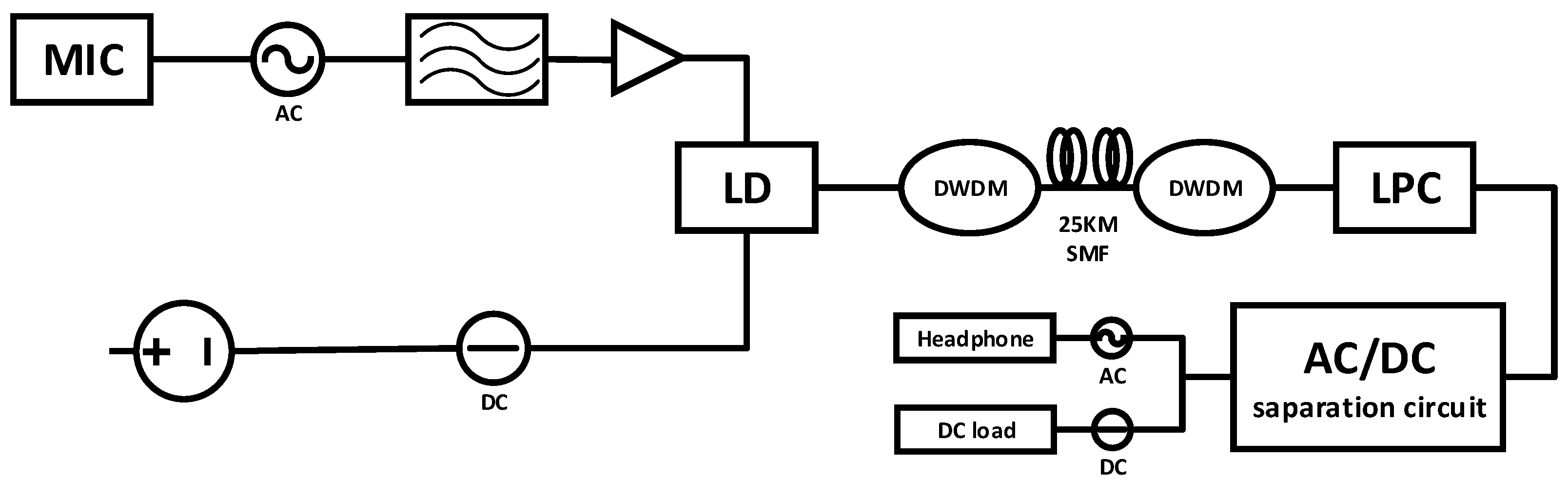
1.2. System Introduction

In 2015, L. Ma, K. Tsujikawa, N. Hanzawa, and their team conducted research on the optical power delivery (OPD) limits of standard single-mode optical fibers (SMFs) at a wavelength of 1550 nm. The study revealed that optical fiber transmission losses and the nonlinear effects of stimulated Raman scattering (SRS) were intrinsic limiting factors affecting the optical output of SMFs [21]. In 2020, H. Helmers, C. Armbruster, and their colleagues developed a fiber-based optical power delivery system capable of providing a continuous power output of up to 6.2 W under common voltages of 3.3 V and 5 V [22]. The following year, in 2021, M. Matsuura, H. Nomoto, and their team enhanced the transmission power of optical power delivery (PoF) links using double-clad optical fibers. They improved the link design to extract higher feeding power from double-clad optical fiber outputs [23]. Building on these advancements, in 2022, E. P. Putra, R. Theivindran, and H. Hasnul proposed the use of optical fibers as a transmission medium for power distribution instead of copper wires, considering recent developments in Power over Fiber (PoF) technology. Research indicates that PoF technology has gained significant momentum over the past decade [24]. Based on these developments, we have designed an audio transmission system. Figure 1 illustrates the system for transmitting analog audio signals over a 25 km single-mode optical fiber (SMF). This audio transmission system primarily consists of a transmitter, a receiver, and the SMF connecting two stations. At the transmitter end, the audio signal is initially converted from a microphone into a low-level alternating current (AC) signal, with the microphone’s peak voltage at just 10 mV. This signal is then amplified by a phase-locked amplifier with a 30× gain. The amplified electrical signal passes through a bandpass filter (20 Hz to 8 kHz) and is driven by a 200 mA current into the DFB-LD’s drive current. This enables the direct modulation of the analog electronic signal, achieving a modulation depth of 78.9%. The DFB-LD emits optical power of 40 mW (16 dBm). The modulated optical power beams are combined via a dense wavelength-division multiplexer (DWDM) with 100 GHz channel spacing and transmitted through a 25 km SMF. The SMF used is a commercial optical fiber with a core diameter of 9 µm, optimized for minimal power loss during audio signal transmission. After 25 km of SMF transmission, the signal is input into the receiving circuit. The receiving circuit comprises a Laser Power Converter (LPC) and an AC/DC separation circuit. The LPC is responsible for converting the optical signal into an electrical signal. The separation circuit consists of two parallel branches. In the first branch, an inductor and resistor are connected in series to extract the direct current portion of the signal, which subsequently powers an electroacoustic transducer. In the second branch, a capacitor and resistor are used to separate the alternating current part of the signal, further converting it into an audio signal.
We use optical fiber as the transmission medium for our system, and signal transmission in optical fiber incurs losses due to factors like wavelength and distance.
In our signal transmission process, we utilize a laser with a specific wavelength as the light source for carrying the signal. To minimize losses and enhance conversion efficiency, we opt for photovoltaic laser-power converters (PV LPCs) designed for single-wavelength lasers, in contrast to solar cells that capture a broad spectrum of light [25]. We employ optical fibers to transmit the signal between the laser and the photovoltaic cell. These optical fibers, commonly made from quartz, function across different laser wavelengths and align with specific loss windows. The most favorable loss windows for optical fibers are at 0.85 μm, 1.31 μm, and 1.55 μm. Generally, optical fiber losses decrease as the wavelength increases. At 0.85 μm, losses are around 2.5 dB/km, while at 1.31 μm, they reduce significantly to approximately 0.35 dB/km. The lowest loss is achieved at 1.55 μm, where it is just 0.20 dB/km [26]. Losses tend to rise for wavelengths beyond 1.65 μm. Therefore, our system employs a laser with a 1.55 μm wavelength, paired with a photovoltaic cell of the corresponding wavelength, to facilitate long-distance signal transmission with minimal loss. An ideal material for developing LPCs suitable for this wavelength is InGaAs lattice matched to an InP substrate.

2. Materials and Methods

2.1. Structure of the InGaAs LPC

The single-junction InGaAs LPC, illustrated in Figure 2, comprises lightly doped (Figure 2a) and heavily doped (Figure 2b) n-InGaAs layers. In the lightly doped n-InGaAs layers, the high doping level of the P-type layer results in a short diffusion length, which limits the collection efficiency for minority carriers. As a result, the N-type laser layer absorbs a significant portion of the laser. In contrast, in heavily doped n-InGaAs layers, the majority of the photocurrent is absorbed within the thick lightly doped P-type layer.
Building upon the conventional InGaAs LPC, we created a vertically structured LPC composed of six sub-cells using InGaAs/InP material to enhance the LPC’s electrical characteristics. We then compared its audio transmission capabilities with a single-junction LPC. Each sub-cell includes an N-type window (with a doping concentration of 6 × 10¹⁸/cm−3), an N-type emitter layer (doping concentration of 1 × 10¹⁸/cm−3), a P-type base layer (doping concentration of 5 × 10¹⁷/cm−3), and a P-type back surface field (BSF) layer (doping concentration of 2.5 × 10¹⁸/cm−3). To achieve optimized electrical characteristics in the multi-junction LPC, each sub-cell was engineered to produce the same photocurrent for current matching, and the reduction in light intensity between the semiconductors adhered to the Beer–Lambert law [27].
I = I 0 exp ( a d )
Therefore, in order to achieve current matching, the thickness of each sub-cell should increase from the surface towards the substrate [28,29,30]. The corresponding thickness of each sub-cell can be calculated using Equation (2):
f N = exp ( a m 1 n 1 d m ) × [ 1 exp ( a d n ) ]
The calculated lengths of each sub-cell are as follows: 147 nm, 180 nm, 210 nm, 327 nm, 559 nm, and 2555 nm. Except for the InP/InP tunnel junction layer, all other layers are doped with either N-type silicon or P-type zinc. To achieve better LPC performance, a highly doped window layer with a thickness of 1.5 μm is grown on top of the converter. On the window layer, a 300 nm thick N-type cap layer is grown to minimize contact resistance and serve as an ohmic contact. The LPC chip has a thickness of 150 μm, and its optimal absorption wavelength is approximately 1520–1530 nm. The LPC structure is shown in Figure 3a. The output voltage of the entire LPC is the sum of the output voltages of the individual sub-LPCs, and the output current is limited by the sub-LPC with the smallest current output. Since the LPC does not require the preparation of isolation cells, it avoids the loss of the active region, resulting in higher voltage output performance.
However, in our system, driving the headphones requires only a very low voltage. The final audio output from the headphone speaker depends on the intensity of the AC current it receives. The greater the intensity of the AC current, the larger the amplitude and volume of diaphragm vibration. In response to this requirement, we developed a laterally structured InGaAs LPC, as shown in Figure 3b. Lateral junctions and conventional vertical junctions serve different functions. A conventional vertical junction increases the photovoltage while keeping the photocurrent constant, whereas a lateral junction increases the photocurrent while keeping the photovoltage constant.
To test the maximum conversion efficiency of the LPC, a 1510 nm butterfly multi-mode PUMP laser (FOL1437) was used as the light source to provide sufficient incident light for testing the prepared LPCs. Figure 4 illustrates the P–V (power–voltage) and I–V (current–voltage) characteristic curves of the four LPCs when exposed to an input optical power of 550 mW. The multi-junction LPC achieves a remarkable maximum conversion efficiency of up to 33.8%. As depicted in the figure, it is evident that under identical conditions, the vertically structured multi-junction LPC operates with a high open-circuit voltage, while the laterally structured multi-junction LPC excels in the short-circuit current state.
We conducted additional tests to assess the conversion efficiency of these LPCs at various incident optical power levels, as depicted in Figure 5. With an increase in the incident optical power from 1 mW to 500 mW, the LPCs’ conversion efficiency displayed a pattern of initially rising and subsequently declining. This behavior primarily results from the temperature elevation in the LPC due to high-intensity illumination, resulting in nonlinear variations in both the light-generated current and the LPC’s reverse saturation current with temperature.

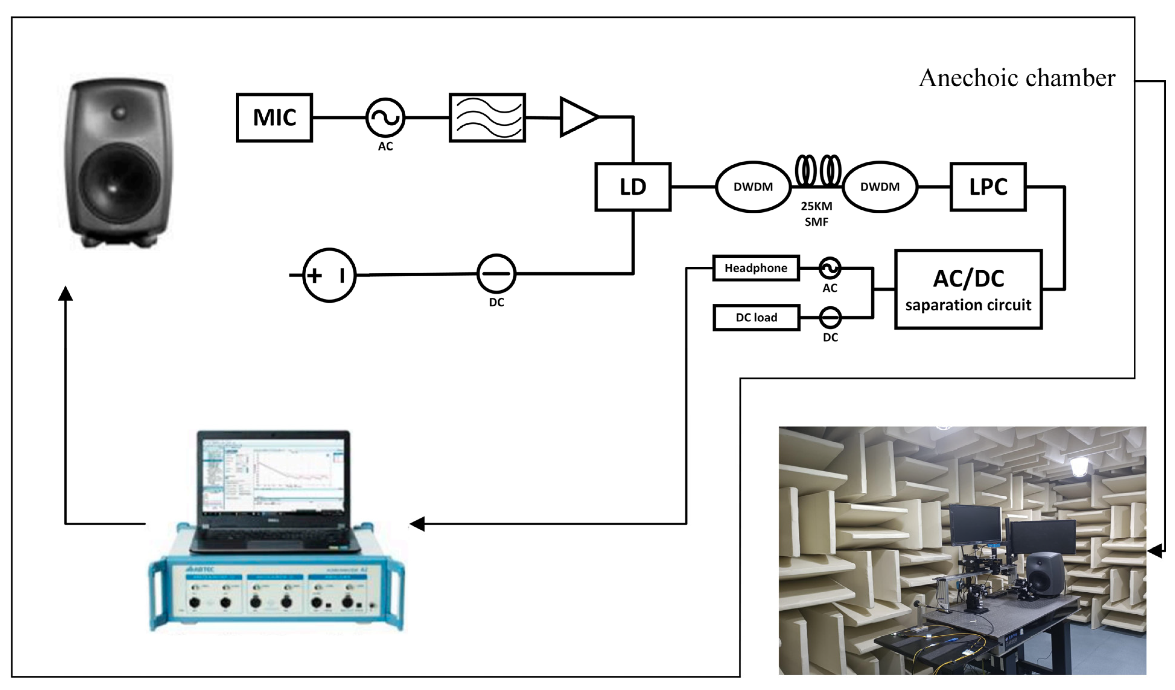
2.2. Audio Test System

We conducted a comparative assessment of the audio transmission capabilities of the LPC structures under typical system operating conditions. To ensure a stable testing environment, all experiments were meticulously carried out within a controlled low-noise anechoic chamber, effectively isolating external noise interference. Within this controlled environment, we rigorously evaluated the quality of audio signals transmitted through various LPC structures. The LPC-connected headphones underwent comprehensive testing, including measurements of total harmonic distortion (THD), output power (AOP), and signal-to-noise ratio (SNR). The audio system utilized the Genelec 8040 B, generating a sinusoidal wave with a 1 kHz frequency and sound pressure levels ranging from 40 dBSPL to 120 dBSPL as the analog signal input. Following a 25 km optical fiber transmission, the audio output from the headphones was meticulously analyzed using a professional audio precision analyzer (ABTECA2) to assess THD, AOP, and SNR. The headphones featured an impedance of 150 ohms and a sensitivity of 111 dB/mW. Through these comprehensive tests, we gained valuable insights into the electrical and audio characteristics of different LPC structures and their performance in audio transmission. The controlled testing environment provided the necessary precision for accurate evaluations while minimizing external disturbances.
Our audio testing system, as depicted in Figure 6, consists of the Genelec 8040 B audio system. It generates a sinusoidal wave with a 1 kHz frequency and sound pressure levels ranging from 40 dBSPL to 120 dBSPL, serving as the analog signal input for the entire system. This signal originates at the microphone receiver end of the primary unit. Following a 25 km optical fiber transmission, it is directed to the LPC within the system. The LPC is connected to headphones, and the resultant output signal undergoes meticulous analysis using the professional audio precision analyzer (AB-TECA2). This analysis includes the measurement of parameters such as loudness, total harmonic distortion (THD), output power (AOP), and signal-to-noise ratio (SNR).

3. Results

We conducted comprehensive tests on different LPC structures to evaluate their electrical and audio characteristics and assess their performance in audio transmission. Using a photovoltaic cell model, we measured important factors such as Voc (open-circuit voltage), Isc (short-circuit current), FF (fill factor), and conversion efficiency of the LPC. Additionally, we compared the audio transmission capabilities of the LPC structures under system operating conditions. To ensure a stable testing environment, all experiments were performed within a controlled low-noise anechoic chamber that effectively isolated external noise interference. Within this environment, we evaluated the quality of audio signals transmitted through various LPC structures. LPC-connected headphones were subjected to comprehensive tests, including measurements of total harmonic distortion (THD), output power (AOP), and signal-to-noise ratio (SNR). The headphones had an impedance of 150 ohms and a sensitivity of 111 dB/mW. Through these comprehensive tests, we gained valuable insights into the electrical and audio characteristics of different LPC structures and their performance in audio transmission. The controlled testing environment provided accurate evaluations while minimizing external disturbances.

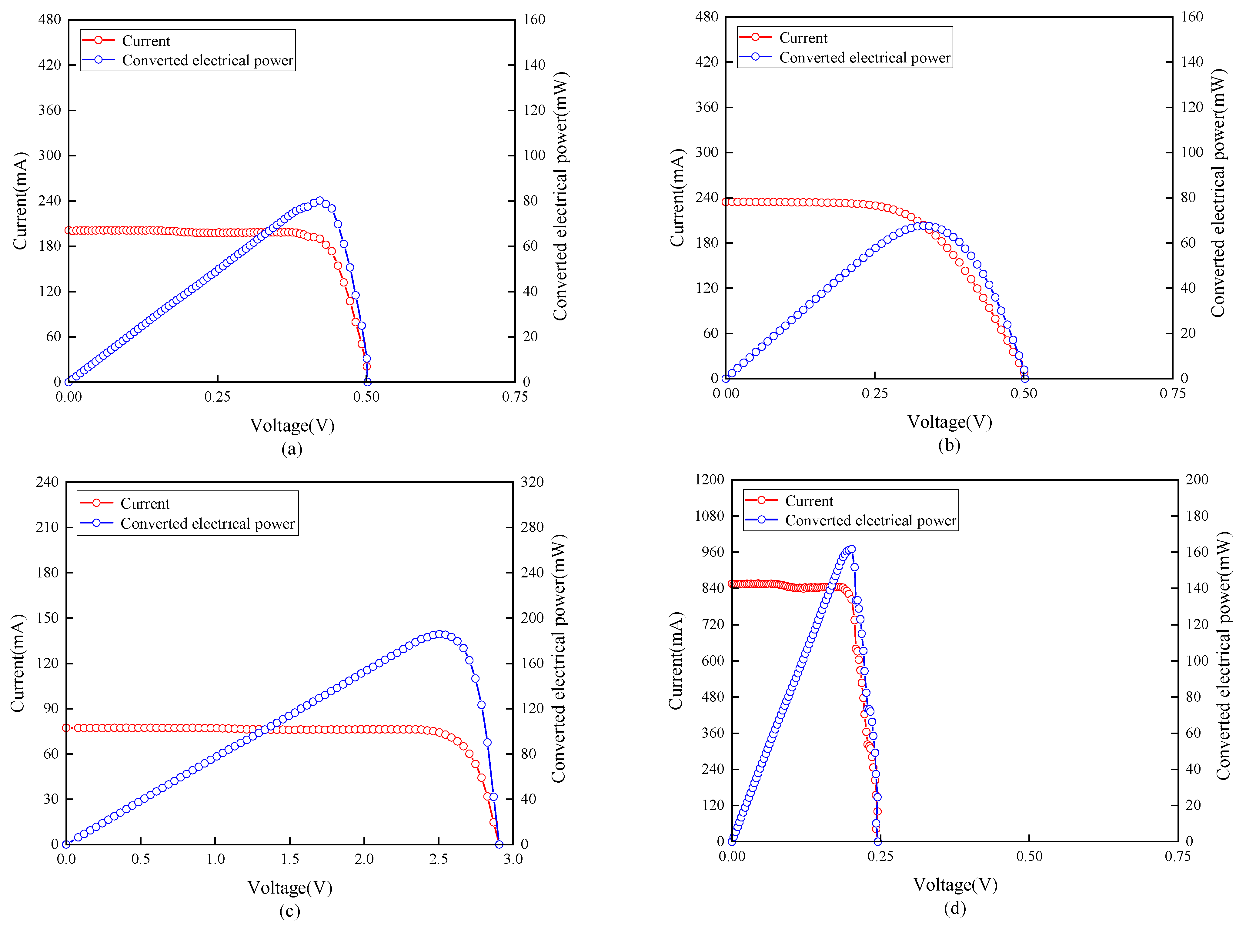
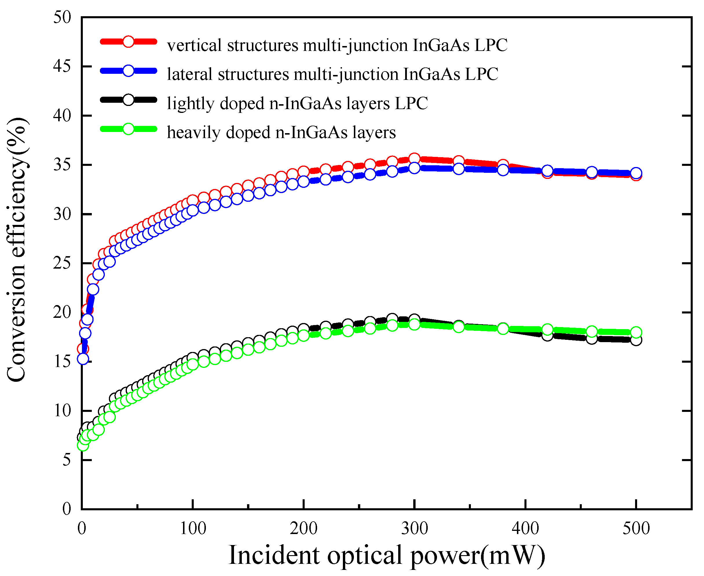
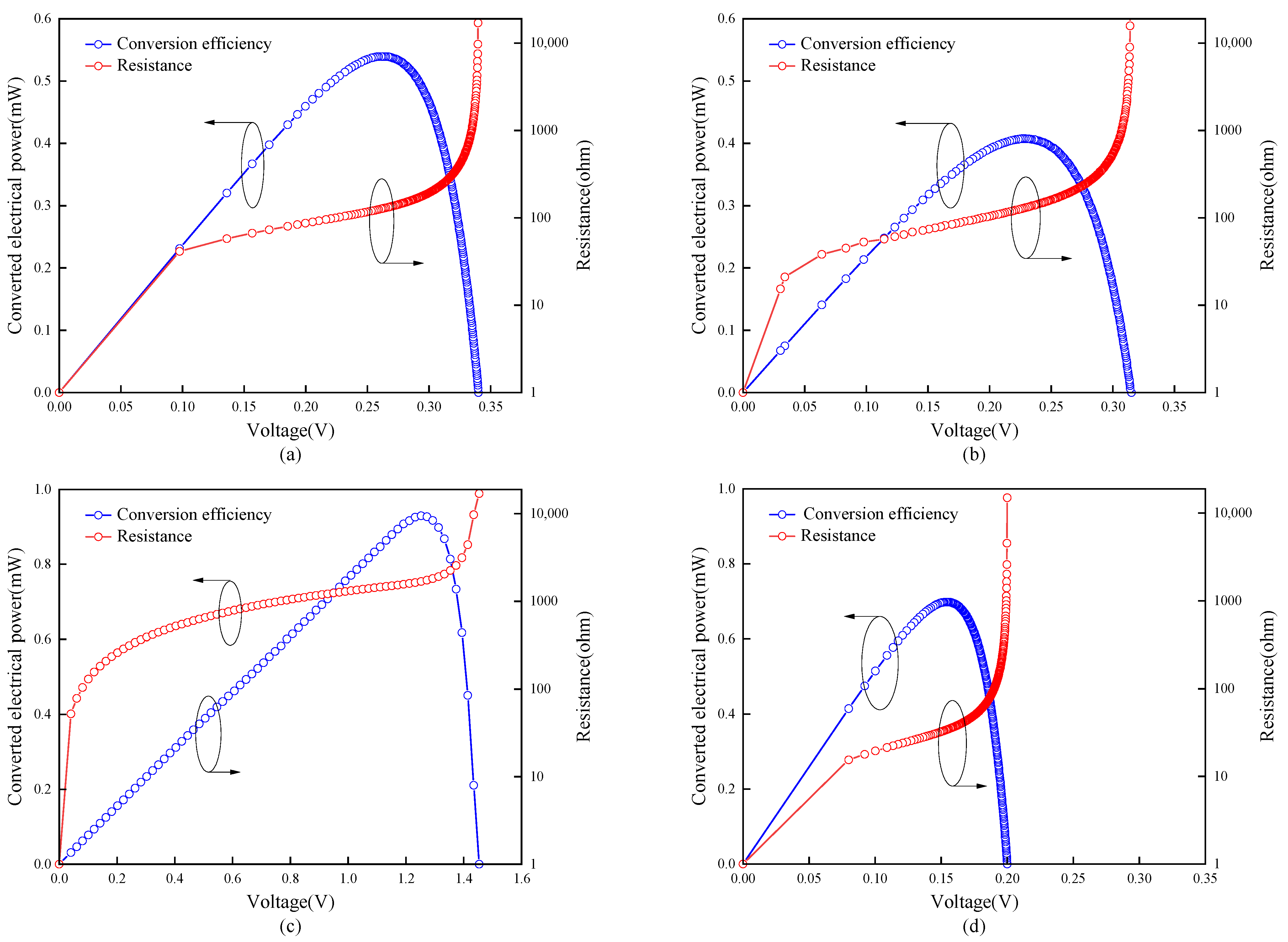
3.1. Power Transmission Performance

The optical signals output by the system are converted into electrical power on the LPC. To test the power output condition of the LPC, we used a parameter analyzer (Keithley 4200A-SCS) to measure the output after a 25 km SMF transmission. Due to the long transmission distance, the 40 mW (16 dBm) laser emitted was reduced to only 6 mW (7.7 dBm) when received by the LPC, considering losses from transmission, connection, and reflection. Because of the weak optical power, the LPC was not operating at its optimal conversion efficiency state under these low-light conditions.
The PV and impedance curves of the four LPCs under these conditions are depicted in Figure 7. However, LPCs developed in this study still exhibited higher conversion efficiency than most traditional LPCs under such low-light conditions. To compare the impact of LPC impedance on its audio transmission quality, we tested the impedance of the four LPCs under the system’s operating light intensity. The vertically structured multi-junction LPC, due to its series structure, significantly increased its impedance, reaching 1687.5112 ohms at the maximum power point. On the other hand, the laterally structured multi-junction LPC’s design allowed it to have lower impedance, with an LPC impedance of 33.8158 ohms at the maximum power point.

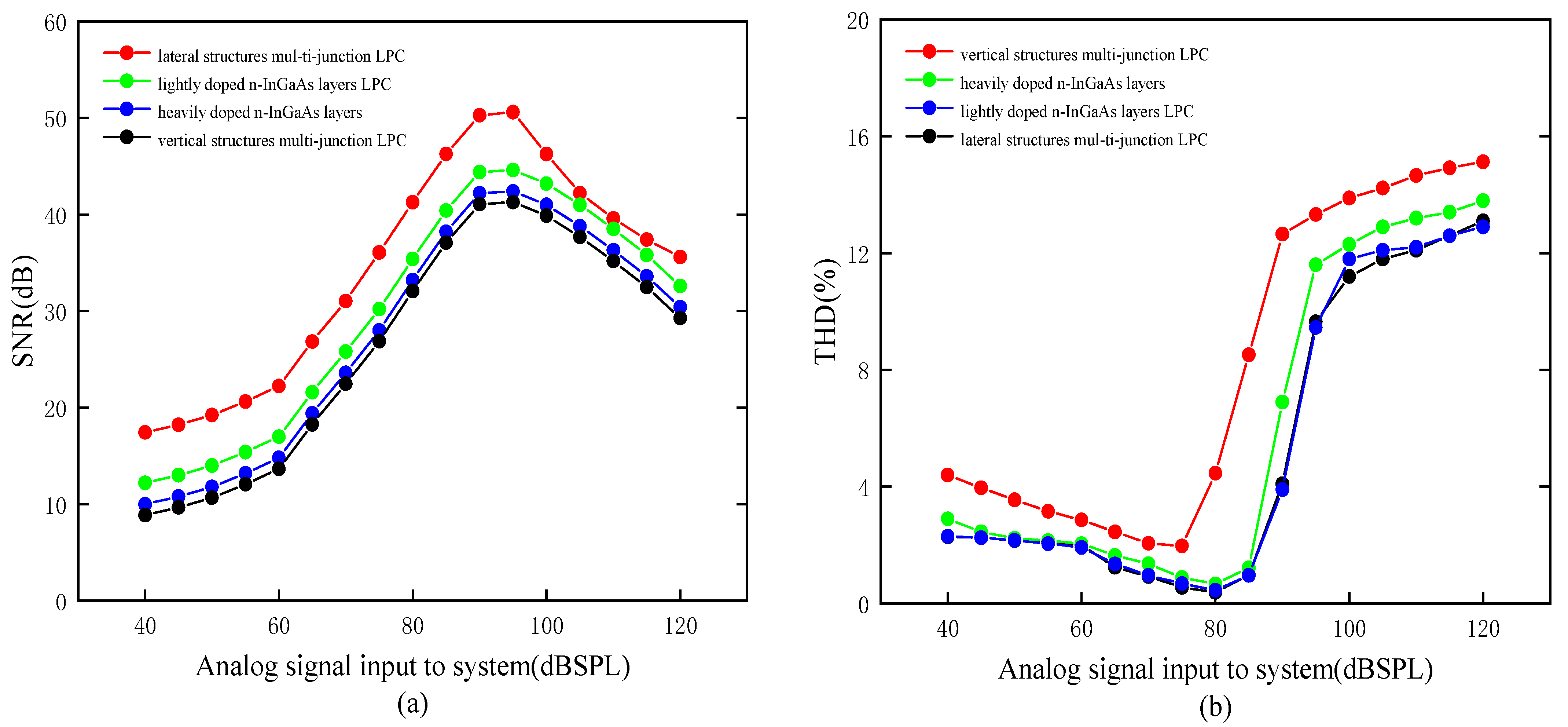
3.2. Audio Signal Transmission Performance

Signal transmission may experience nonlinear distortion due to factors such as fiber loss and fiber stress. To control the effects of these variables, audio tests were performed using standardized 25 km single-mode fiber transmission. Therefore, in experiments, the loudness, total harmonic distortion (THD), and signal-to-noise ratio (SNR) of audio signals output by different single-junction LPCs under the same transmission conditions were tested to evaluate the transmission performance. The noise power level in this audio system remains stable at a fixed transmission distance and input frequency.
The audio loudness performance of the four LPCs under 25 km SMF transmission is depicted in Figure 8. The results show that there is minimal difference in audio loudness transmission capability between the two single-junction LPCs and the vertically structured multi-junction LPC, with the single-junction LPC even slightly outperforming the vertically structured multi-junction LPC. The single-junction LPC achieves a peak audio loudness output of 9.4 mVrms. In contrast, the laterally structured multi-junction LPC exhibits excellent audio loudness transmission capacity, reaching a maximum audio loudness output of 12.8 mVrms. This performance is attributed to the high output short-circuit current and low impedance of this LPC structure.
Various factors can influence the ultimate output signal in optical fiber systems. While it is challenging to optimize every single factor, our research has concentrated on maintaining the consistency of optical fiber output when different LPCs input signals. The research team has diligently worked toward this goal. We have assessed audio transmission efficiency by measuring the signal-to-noise ratio (SNR) and total harmonic distortion (THD) of the output audio signals across various input sound pressure levels.
As depicted in Figure 9a, when the input sound pressure is low, LPCs with weaker output signals exhibit a lower SNR due to a higher proportion of electrical noise. In this context, a laterally structured multi-junction LPC, maintaining higher signal strength, retains an advantage. THD measures harmonic distortion in the transmitted signal compared to the original signal. A lower THD indicates reduced distortion, improved signal transmission performance, and an enhanced audio experience. The sound pressure level at which THD distortion reaches 10% defines the Acoustic Output Power (AOP) of the device, representing the maximum sound pressure level the system can handle without significant distortion. Exceeding this sound pressure level results in substantial distortion.
As depicted in Figure 9b, for two single-junction LPCs and the vertically structured multi-junction LPC, the THD values for analog audio output consistently remain below 3% for input sound pressures ranging from approximately 40 dBSPL to 85 dBSPL, indicating very low distortion levels. As the input sound pressure gradually increases, the signal intensity in the optical fiber and nonlinear effects also increase, leading to a gradual rise in the proportion of harmonic components in the audio signal, resulting in an increase in THD values. The AOP point is reached at around 90 dBSPL. In contrast, the laterally structured multi-junction LPC, when compared to other LPCs, exhibits a lower AOP point because the high signal strength of the laterally structured multi-junction LPC generates more harmonic components during the transmission process. In this regard, the laterally structured multi-junction LPC does not maintain an advantage.
However, considering the system’s operating environment, wherein the system saturates at 95 dBSPL, the disadvantage of the lower AOP point does not significantly impact the system’s application of the laterally structured multi-junction LPC in most cases.

4. Discussion

Through our testing, we have found that the application of the developed laterally structured multi-junction LPC maximizes the system’s audio conversion capabilities. We conducted tests on various LPC structures, excluding the impact of conversion efficiency, fill factor, and other factors on audio signal transmission. As an example, we evaluated the influence of open-circuit voltage and short-circuit current values for each LPC on audio transmission, using an input sound pressure level (SPL) of 60 dBSPL. As shown in Figure 10, the two axes on the plane represent the open-circuit voltage and short-circuit current of the LPC under these operating conditions, and the vertical axis represents the LPC’s audio loudness output under these conditions. From the figure, it can be observed that under the same test conditions, the audio output level of the single-junction LPC ranges from approximately 2 to 5 mVrms. When using a vertically structured multi-junction LPC, the audio output level ranges from about 4 to 5 mVrms. At the same time, using a laterally structured multi-junction LPC can produce audio output levels ranging from 9.5 to 12.5 mVrms.
The data show that in the testing of single-junction LPCs, as the electrical characteristics of the LPCs improve, their audio transmission capabilities also increase correspondingly. However, comparative tests of multi-junction LPCs have shown that through vertical connection, the audio transmission capabilities of LPCs are, in fact, reduced. This can be attributed to the following reasons: First, when using vertically structured multi-junction LPCs, audio signals do not undergo the same enhancement as electrical power. The increased impedance of multi-junction LPCs actually amplifies the transmission losses of audio signals. Second, just as the short-circuit current of multi-junction LPCs is limited by its weakest junction, when audio signals are input into multi-junction LPCs, the poorest electrical characteristics of one junction restrict the output audio performance.
Based on the above conclusions, we hypothesized and developed laterally structured multi-junction LPCs to optimize the system’s audio transmission capabilities. The characteristics of this LPC structure, including high short-circuit current and low impedance, significantly enhance audio signal loudness and SNR during transmission, although the upper limit for audio distortion has decreased somewhat.

5. Conclusions

This paper is based on the development of a remote, low-power communication system and investigates the impact of LPCs, which are important components for power and signal transmission, on the audio transmission quality of such systems. In line with the wavelength used in the system, we chose InGaAs material to fabricate LPCs and explored key factors influencing audio transmission quality by modifying LPC internal doping composition, the number of LPC junctions, and the connection method of multi-junction LPCs.
The investigation revealed that the short-circuit current and impedance magnitude of LPCs are crucial factors affecting audio transmission quality. Conventional single-junction LPCs exhibit consistent audio transmission capabilities with little variation in quality. In contrast, when using vertical connection in multi-junction LPCs, while the open-circuit voltage increases, it also raises the impedance, limiting the short-circuit current and leading to a decrease in output audio quality.
To address this phenomenon, we developed vertically structured multi-junction LPCs, which increase the short-circuit current and reduce LPC impedance. While this approach lowers the upper limit of audio distortion during transmission, it significantly enhances audio loudness and SNR in the output audio. This research has pioneered the discovery of the impacts of LPCs with different structures on audio signal transmission, and we have successfully fabricated the most suitable LPC structure for system audio transmission, validating its effectiveness. This finding can also be applied to other systems using fiber-optic LPCs for audio signal transmission, providing valuable insights for improving audio quality in such systems.

Author Contributions

Conceptualization, Y.Z. (Yikai Zhou) and C.G.; methodology, Y.Z. (Yikai Zhou) and C.G.; software, Y.Z. (Yihao Zhang), P.L. and H.Q.; validation, Y.Z. (Yikai Zhou) and Y.Z. (Yihao Zhang); investigation, Y.Z. (Yikai Zhou), R.Z. and W.C.; resources, C.G. and H.L.; data curation, Y.Z. (Yikai Zhou), S.L. and X.L.; writing—original draft preparation, Y.Z. (Yikai Zhou); writing—review and editing, H.L.; supervision, C.G. and H.L.; funding acquisition, H.L. All authors have read and agreed to the published version of the manuscript.

Funding

This research was funded by the International Science and Technology Cooperation Key Research and Development Program of the Science and Technology Agency in Hubei Province (No. 2021EHB018), the Project of Outstanding Young and Middle-aged Scientific Innovation Team of Colleges and Universities in Hubei Province (No. T201907), and the Overseas Expertise Introduction Center for Discipline Innovation (111 Center).

Institutional Review Board Statement

Not applicable.

Informed Consent Statement

Not applicable.

Data Availability Statement

Not applicable.

Conflicts of Interest

The authors declare no conflict of interest.

References

  1. Ogudo, K.A.; Mthethwa, M.H.; Nestor, D.M.J. Comparative Analysis of Fibre Optic and Copper Cables for High-Speed Communication: South African Context. In Proceedings of the 2019 International Conference on Advances in Big Data, Computing and Data Communication Systems (IcABCD), Winterton, South Africa, 5–6 August 2019; pp. 1–8. [Google Scholar]
  2. Chai, S.; Guo, C.; Guan, C.; Fang, L. Deep Learning-Based Speech Enhancement of an Extrinsic Fabry–Perot Interferometric Fiber Acoustic Sensor System. Sensors 2023, 23, 3574. [Google Scholar] [CrossRef]
  3. Chen, H.; Guan, C.; Lv, H.; Guo, C.; Chai, S. Improved Optical Path Structure for Symmetric Demodulation Method in EFPI Fiber Optic Acoustic Sensors Using Wavelength Division Multiplexing. Sensors 2023, 23, 4985. [Google Scholar] [CrossRef] [PubMed]
  4. Guo, C.; Guan, C.; Lv, H.; Chai, S.; Chen, H. Multi-Channel Long-Distance Audio Transmission System Using Power-over-Fiber Technology. Photonics 2023, 10, 521. [Google Scholar] [CrossRef]
  5. Razykov, T.M.; Ferekides, C.S.; Morel, D.; Stefanakos, E.; Ullal, H.S.; Upadhyaya, H.M. Solar photovoltaic electricity: Current status and future prospects. Sol. Energy 2011, 85, 1580–1608. [Google Scholar] [CrossRef]
  6. Green, M.A.; Emery, K.; Hishikawa, Y.; Warta, W. Solar cell efficiency tables (version 37). Prog. Photovolt. Res. Appl. 2011, 19, 84–92. [Google Scholar] [CrossRef]
  7. Rueda, P.; Lisbona, E.F.; Herrero, M.D. Capacitance measurements on multi-junction solar cells. In Proceedings of the 3rd World Conference OnPhotovoltaic Energy Conversion, Osaka, Japan, 11–18 May 2003; Volume 1, pp. 817–820. [Google Scholar]
  8. De Nazare, F.V.B.; Werneck, M.M. Hybrid Optoelectronic Sensor for Current and Temperature Monitoring in Overhead Transmission Lines. IEEE Sens. J. 2012, 12, 1193–1194. [Google Scholar] [CrossRef]
  9. Steinsiek, F. Wireless Power Transmission Experiment as an Early Contribution to Planetary Exploration Missions. In Proceedings of the 54th International Astronautical Congress of the International Astronautical Federation, the International Academy of Astronautics, and the International Institute of Space Law, Bremen, Germany, 29 September–3 October 2003. [Google Scholar]
  10. Wu, T.-C.; Liu, J.; Werthen, J.-G. Watt range electrical power output through single optical fiber for remote, safe, isolated powering applications. In Optical Technologies for Arming, Safing, Fuzing, and Firing; SPIE: Bellingham, WA, USA, 2005. [Google Scholar]
  11. Khvostikov, V.P.; Sorokina, S.V.; Potapovich, N.S.; Khvostikova, O.A.; Timoshina, N.K.; Shvarts, M.Z. Modification of Photovoltaic Laser-Power (λ = 808 nm) Converters Grown by LPE. Semiconductors 2018, 52, 366–370. [Google Scholar] [CrossRef]
  12. Zhao, Y.; Liang, P.; Ren, H.; Han, P. Enhanced efficiency in 808 nm GaAs laser power converters via gradient doping. AIP Adv. 2019, 9, 105206. [Google Scholar] [CrossRef]
  13. Pilling, N.A.; Holmes, R. Low-power optical current measurement system employing a hybrid transmitter. IEE Proc. Part A 1994, 141, 129–134. [Google Scholar] [CrossRef]
  14. Zhang, S.; Tsonev, D.; Videv, S.; Ghosh, S.; Turnbull, G.A.; Samuel, I.D.W.; Haas, H. Organic solar cells as high-speed data detectors for visible light communication. Optica 2015, 2, 607–610. [Google Scholar] [CrossRef]
  15. Wang, Z.; Tsonev, D.; Videv, S.; Haas, H. On the Design of a Solar-Panel Receiver for Optical Wireless Communications with Simultaneous Energy Harvesting. IEEE J. Sel. Areas Commun. 2015, 33, 1612–1623. [Google Scholar] [CrossRef]
  16. Shin, W.-H.; Yang, S.-H.; Kwon, D.-H.; Han, S.-K. Self-reverse-biased solar panel optical receiver for simultaneous visible light communication and energy harvesting. Opt. Express 2016, 24, A1300–A1305. [Google Scholar] [CrossRef] [PubMed]
  17. Fafard, S.; Masson, D.P. Perspective on photovoltaic optical power converters. J. Appl. Phys. 2021, 130, 160901. [Google Scholar] [CrossRef]
  18. Fafard, S.; Masson, D.; Werthen, J.-G.; Liu, J.; Wu, T.-C.; Hundsberger, C.; Schwarzfischer, M.; Steinle, G.; Gaertner, C.; Piemonte, C.; et al. Power and Spectral Range Characteristics for Optical Power Converters. Energies 2021, 14, 4395. [Google Scholar] [CrossRef]
  19. Fafard, S.; Masson, D.P. High-Efficiency and High-Power Multijunction InGaAs/InP Photovoltaic Laser Power Converters for 1470 nm. Photonics 2022, 9, 438. [Google Scholar] [CrossRef]
  20. Fafard, S.; Masson, D. Vertical Multi-Junction Laser Power Converters with 61% Efficiency at 30 W Output Power and with Tolerance to Beam Non-Uniformity, Partial Illumination, and Beam Displacement. Photonics 2023, 10, 940. [Google Scholar] [CrossRef]
  21. Ma, L.; Tsujikawa, K.; Hanzawa, N.; Yamamoto, F. Design of optical power delivery network based on power limitation of standard single-mode fiber at a wavelength of 1550 nm. Appl. Opt. 2015, 54, 3720–3724. [Google Scholar] [CrossRef]
  22. Helmers, H.; Armbruster, C.; von Ravenstein, M.; Derix, D.; Schöner, C. 6-W Optical Power Link with Integrated Optical Data Transmission. IEEE Trans. Power Electron. 2020, 35, 7904–7909. [Google Scholar] [CrossRef]
  23. Matsuura, M.; Nomoto, H.; Mamiya, H.; Higuchi, T.; Fafard, S. Over 40-W Electric Power and Optical Data Transmission Using an Optical Fiber. IEEE Trans. Power Electron. 2021, 36, 4532–4539. [Google Scholar] [CrossRef]
  24. Putra, E.P.; Theivindran, R.; Hasnul, H.; Lee, H.J.; Ker, P.J.; Jamaludin, M.D.Z.; Awang, R.; Yusof, F.A.M. Technology update on patent and development trend of power over fiber: A critical review and future prospects. J. Photonics Energy 2023, 13, 011001. [Google Scholar] [CrossRef]
  25. Sudharsanan, R.; Krut, D.; Isshiki, T.; Cotal, H.; Mesropian, S.; Masalykin, A.; Karam, N.H. A 53% high efficiency GaAs vertically integrated multi-junction laser power converter. In Proceedings of the LEOS 2008—21st Annual Meeting of the IEEE Lasers and Electro-Optics Society, Newport Beach, CA, USA, 9–13 November 2008; p. 30. [Google Scholar]
  26. Akand, T.; Islam, M.J.; Kaysir, M.R. Low loss hollow-core optical fibers conjoining tube lattice and revolver structures. Results Opt. 2020, 1, 100008. [Google Scholar] [CrossRef]
  27. Palik, E.D. Handbook of Optical Constants of Solids; Academic Press: New York, NY, USA, 1985; pp. 429–443. [Google Scholar]
  28. Algora, C.; García, I.; Delgado, M.; Pea, R.; Vázquez, C.; Hinojosa, M.; Rey-Stolle, I. Beaming power: Photovoltaic laser power converters for power-by-light. Joule 2022, 6, 340–368. [Google Scholar] [CrossRef]
  29. Kalyuzhnyy, N.A.; Emelyanov, V.M.; Evstropov, V.V.; Mintairov, S.A.; Mintairov, M.A.; Nahimovich, M.V.; Salii, R.A.; Shvarts, M.Z. Optimization of photoelectric parameters of InGaAs metamorphic laser (λ = 1064 nm) power converters with over 50% efficiency. Sol. Energy Mater. Sol. Cells 2020, 217, 110710. [Google Scholar] [CrossRef]
  30. Pearsall, T.P.; Hirtz, J.P. The carrier mobilities in Ga0.47In0.53as grown by organo-mettalic CVD and liquid-phase epitaxy. J. Cryst. Growth 1981, 54, 127–131. [Google Scholar] [CrossRef]
Figure 1. Schematic diagram of the transmission structure of the system.
Photonics 10 01257 g001
Figure 2. LPC structures: (a) lightly doped n-InGaAs layers and (b) heavily doped n-InGaAs layers.
Photonics 10 01257 g002
Figure 3. (a) Schematic diagram of the structure of vertically structured multi-junction InGaAs LPC, (b) schematic diagram of the structure of laterally structured multi-junction InGaAs LPC.
Photonics 10 01257 g003
Figure 4. P–I–V curves of the four LPCs at 550 mW: (a) lightly doped n-InGaAs layers LPC, (b) heavily doped n-InGaAs layers, (c) vertically structured multi-junction LPC, (d) laterally structured multi-junction LPC.
Photonics 10 01257 g004
Figure 5. Conversion efficiency change curve of LPCs at different incident light intensities.
Photonics 10 01257 g005
Figure 6. Schematic diagram of the audio test system and anechoic chamber environment.
Photonics 10 01257 g006
Figure 7. P–R–V curves of the four LPCs at 7.7 dBm: (a) lightly doped n-InGaAs layers LPC, (b) heavily doped n-InGaAs layers, (c) vertically structured multi-junction InGaAs LPC, (d) laterally structured multi-junction InGaAs LPC.
Photonics 10 01257 g007
Figure 8. The audio loudness of the four LPCs under 25 km SMF transmission.
Photonics 10 01257 g008
Figure 9. (a) Signal-to-noise ratio (SNR) of the four LPCs’ output audio signals, and (b) total harmonic distortion (THD) of the four LPCs’ output audio signals.
Photonics 10 01257 g009
Figure 10. The relationship between different LPC open-circuit voltage, short-circuit current, and audio loudness (input 60 dBSPL).
Photonics 10 01257 g010
Disclaimer/Publisher’s Note: The statements, opinions and data contained in all publications are solely those of the individual author(s) and contributor(s) and not of MDPI and/or the editor(s). MDPI and/or the editor(s) disclaim responsibility for any injury to people or property resulting from any ideas, methods, instructions or products referred to in the content.

