1. Introduction
Switched systems have received extensive attention since many actual systems are essentially multi-modal, such as servo mechanism systems, manipulator robots, power electronics systems, flight control systems, etc. [
1,
2,
3,
4]. The research motivation of this paper stems from three key engineering challenges in the switched systems: (1) partially unstabilizable subsystems: practical switched systems often contain subsystems that cannot be stabilized inherently, necessitating specialized control approaches; (2) networked constraints: bandwidth limitations in networked systems require quantized control methods to handle data transmission efficiently [
5]; (3) actuator saturation: widespread saturation nonlinearities due to physical constraints demand stability-preserving controller designs. By addressing the mode mismatch caused by sampling, the study aims to develop a unified control algorithm that ensures system stability despite quantization, sampling, and saturation in continuous-time switched systems with unstabilizable subsystems.
For the switched systems with unstabilizable subsystems, many studies exist. An et al. [
6] proposed a dwell-time-based control algorithm for a class of switched positive systems with all unstabilizable subsystems. Li et al. [
7] developed a sampled data stabilization scheme for switched nonlinear systems where every subsystem could be unstabilizable. For switched linear systems containing both stabilizable and unstabilizable subsystems under slow- and fast-switching constraints, Wang et al. [
8] constructed a time-varying mode controller to guarantee the system stability. For continuous-time switched systems with partially unstabilizable subsystems experiencing quantization and denial-of-service (DoS) attacks, Yan et al. [
9] designed a stability-guaranteeing framework. Li et al. [
10] investigated the stability of switched linear systems with input saturation and time-varying delays, where delay-dependent switching combines stabilizable and unstabilizable subsystems.
The quantized control of the switched system is also worthy of our attention. Ahmadzadeh et al. [
11] studied robust
control and event-triggered sampling co-design for uncertain switched singular systems with output quantization. Parivallal et al. [
12] investigated the guaranteed-cost consensus control problem for nonlinear systems under switching topologies considering data quantization effects. A quantized sliding mode controller for nonlinear stochastic switched systems was developed by Qi et al. [
13]. In [
14], Qi et al. proposed decentralized quantized control combined with two-terminal event-triggered communication to enhance resilience against network-induced attacks. The stability of switched linear systems under quantization and event-triggered communication was studied by Zhao et al. [
15]. Ahmadzadeh et al. [
16] investigated event-triggered variable structure control for nonlinear switched descriptor systems with matched and mismatched disturbances. An adaptive neural network observer utilizing quantized output data was designed by Chen et al. [
17] for switched systems. Cheng et al. [
18] presented a static output feedback strategy for fuzzy Markov switched singular perturbation systems with spoofing attacks and quantized measured outputs. Zou et al. [
19] addressed finite-time bipartite synchronization of coupled competitive neural networks subject to switching parameters and delays. Cheng et al. [
20,
21] and Zhao et al. [
22] further investigated non-stationary filtering switched systems and fuzzy Markov switched affinity systems under the combined effects of deception attacks and data quantization. In Maity et al. [
23], the authors proposed the joint selection method of the quantizers and the controller. Yan et al. [
24] proposed quantized controller designs for switched systems affected by delay and disturbance.
Actuator saturation is another key factor that can degrade performance and even compromise system stability. Chen et al. [
25] studied the aperiodic sampled data control problem of the switched network affected by actuator saturation. Zhao et al. [
26] addressed exponential stabilization for networked cascade control systems constrained by actuator saturation. In Ahmadzadeh et al. [
27], a two-layer supervisory control scheme is proposed for discrete-time linear systems with state/input constraints. In Kumar et al. [
28], the linear system affected by actuator saturation is experimentally studied. Wang et al. [
29] developed a continuous dynamic gain scheduling control strategy for switched systems experiencing input saturation. Actuator failures including saturation, partial failure, interruption, and offset were considered in Yin et al. [
30]. Through the application of a multi-time-varying Lyapunov function, sufficient conditions for exponential stabilization of the switched systems were established in Ma et al. [
31]. This paper mainly refers to the method in [
31] for handling saturated nonlinearity. Due to the lack of discussion of sampling and quantization issues in [
31], how to describe the saturation controller as a linear combination of sampled states as in [
31] is a difficult problem in this paper.
This paper integrates the influences of unstabilizable subsystems, data quantization, and actuator saturation into the analysis of switched systems. For switched systems subject to quantization and actuator saturation, an output feedback controller based on a sector-bounded quantizer was designed by Wu et al. [
32]. In stability analysis, the attenuation of the quantization error plays a key role. Because of the advantages of simple design and easy implementation, this paper will adopt a static quantizer.
Table 1 provides a detailed comparison between the quantizer, quantization level, sampling situations, and saturation handling methods used in this paper and reference [
32]. Considering that finite-level quantizers have more practical value and sampling is an indispensable key step in signal transmission, the linearized saturation function can simplify the system analysis process. Therefore, the results of this paper are superior to those in [
32] both from a practical perspective and in terms of processing methods.
The key research challenges in this paper include (1) designing a static quantizer with fixed error bounds that accounts for the polyhedral constraints imposed by actuator saturation; (2) precisely defining the attraction domain and the invariant set under inherent quantization errors to ensure system performance analysis; and (3) guaranteeing that the Lyapunov function decreases in the optimal case under multiple factors (quantization, saturation, etc.) for stability verification.
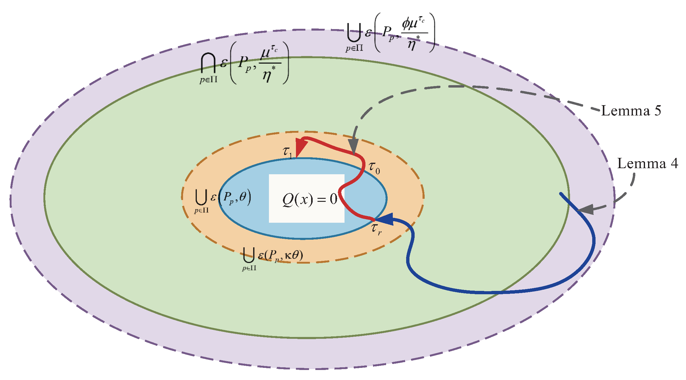
In light of the challenges discussed above, the following methodologies are introduced: (1) By restricting the initial state (see Condition 1) and the relationship between an ellipse and a polyhedral (see Condition 2), we claim that the system states at sampling times are always located within a polyhedron (see Claim 1, which is proven in
Section 4.3). Then, the saturated controller can be expressed as a linear combination relating to sampled quantized states (see (
5)). (2) For the designed quantization rules, if the state is within a given annular area
, we can guarantee the decrement rate of the Lyapunov function in the optimal case (see (
18)). (3) We pursue an attraction domain
(see Condition 1, which is smaller than the outer ring of the annular area) and an invariant set
(see Lemma 5, which is larger than the inner ring of the annular area) based on the union or intersection of ellipses to guarantee the system stability (see Theorem 1).
The remainder of this paper is structured as follows: In
Section 2, we introduce the problem under consideration, including the plant definition, description of stabilizable and unstabilizable subintervals, quantization and control rules, and the primary objective of the study. By analyzing the rate of increase or decrease rate of the Lyapunov function in
Section 3, the stability of the system can be established in
Section 4. Furthermore, the controller design method and optimization problem for attractive regions are also discussed in
Section 5 and
Section 6, respectively.
Section 7 presents simulation studies that validate the effectiveness of the obtained results. The conclusions in
Section 8 summarize the results of this paper and directions for future research.
Notation: Let denote the set of all real numbers, and means . represents the n-dimensional Euclidean space. The set of all positive integers is denoted by , and is defined as . The symbol “T” refers to the transposition of a matrix. Unless otherwise indicated, denotes the Euclidean 2-norm, where . The norm induced by the specified vector norm is adopted for matrices. The notation stands for the left-hand limit of x at time . The sampling period is denoted by . For , we set and whenever , . For a set , the symbols Cl , Int , and denote its closure, interior, and boundary, respectively. The maximum and minimum eigenvalues of a matrix P are denoted by and , respectively.
2. Methodology
The system configuration discussed in this paper is presented in
Figure 1. For a given sampling period
, the sensor acquires the plant state
along with the mode information
at sampling times
. Due to limited network bandwidth, the state
is quantized as
by the quantizer according to the special quantization rules (see
Section 2.3). Subsequently, the encoder encodes
into an integer
and transmits
and
to the controller through the network. We assume that the network is delay-free and transmission-reliable. Then, the controller can receive the transmitted signals at
under the role of the decoder and updates the control algorithm
by using a zero-order holder (ZOH). Unless otherwise specified, we set
.
2.1. Plant Definition
The plant shown in
Figure 1 is modeled by the following switched systems:
where
is the system state and
is the control input. The signal
denotes the system mode at time
t, where
is a finite index set. We call discontinuities of
“switching times” or “switches”.
denotes the total count of switches occurring over the time interval
, where
. The saturation function
is defined as
with
, where
is the
m-th component of
u, and
denotes a generic symbolic function.
Assumption 1.
The index set Π is partitioned into two subsets, and , corresponding to stabilizable and unstabilizable index sets, respectively. That is, if the system mode , there exists a feedback matrix such that is Hurwitz. Otherwise, if , there is no feedback matrix to guarantee that is Hurwitz.
- 1.
There exists a dwell time satisfying and .
- 2.
For a constant , there exists an average dwell time satisfying .
2.2. Description of Stabilizable and Unstabilizable Subintervals
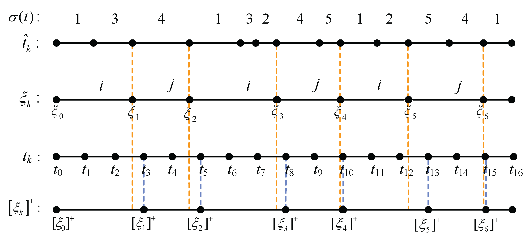
If we let and denote and as the intervals during which stabilizable and unstabilizable subsystems are, respectively, active, then the signal is adopted to represent the total time during which the stabilizable and unstabilizable subsystems are active in the interval . Moreover, and denote, respectively, the activation times of the stabilizable and unstabilizable subsystems in .
An illustration is provided in
Figure 2 to aid in understanding the variables used in this paper, where modes
and modes
. The signal
is used to establish the global bound for sampling times in
Section 3. Obviously,
may not necessarily be a sampling time, while
and
are included in the set of sampling times, i.e.,
.
2.3. Quantization and Control Rules
The memoryless quantizer proposed in Wakaiki et al. [
33] is adopted here. Let
be the finite partition of
. Given an arbitrary bounded region
, one can find a finite subset
of an index set
so that
. The quantizer is formulated as follows:
Moreover, we assume that
if Cl
contains the origin. Obviously, a sufficiently large constant
can be found such that
, where ellipsoid
and matrix
are defined in (
4) and (
6), respectively.
For the quantization function
defined in (
2), the control input is set as
under the role of ZOH, where
is the feedback matrix to be designed. Obviously,
must not be Hurwitz if
by Assumption 1.
The following definition and conditions are useful to establish Claim 1, which is instrumental in proving the main results and will be verified in
Section 4.3.
Definition 1.
Considering a positive-definite matrix and a matrix that is designed, we respectively define an ellipsoid and a polyhedron as follows:where denotes the lth row of the matrix G. Condition 1.
For the given arbitrary constants and , the initial state satisfies .
Condition 2.
For the given μ and , there exists a matrix such that with .
Claim 1.
For the ellipsoid and the polyhedron defined in (4), if Conditions 1 and 2 hold, then . Remark 1.
Since μ and are arbitrary constants, if we set μ to be sufficiently large compared to , then Condition 1 can always hold. Moreover, at the beginning of the proof of Theorem 2, we verified that if Condition 5 holds, then shown in Condition 2 is equivalent to (36). Therefore, we can obtain and by solving (36) and then obtain the matrix that guarantees Condition 2 by .
Lemma 1
([
31])
. For any and such that , one haswhere denotes the convex hull. is a diagonal matrix with 1 or 0 elements, and .If Claim 1 holds, the constrained control input can be formulated aswhere , ,..., and . Hence, the closed-loop system formed by (1) and (5) is expressed as Remark 2.
From Lemma 1, it can be seen that the difficulty in obtaining the expression (5) lies in determining how to ensure that the moduli of all elements of are less than 1, that is, . To solve this problem, we introduce Claim 1 and prove it in Section 4.3. The following lemma obviously holds by using the properties of the static quantizer proposed in Ma et al. [
31].
Lemma 2.
If , there exist positive numbers and such that the quantizer defined in (2) satisfiesfor all , and , in whichand , , and with and . 2.4. Main Purpose
The purpose of this paper is to determine a switching condition (
7) that guarantees that all trajectories of the switched system (
5) enter a certain neighborhood
around the origin and stay confined within a larger neighborhood
.
If we let , the stability results of the closed-loop system can be established by discussing the following four situations:
Case 1: , and no switching occurs in .
Case 2: , and a switch occurs in .
Case 3: , and no switching occurs in .
Case 4: , and a switch occurs in .
For the positive-definite matrix
and the constants
and
given in Claim 1, we consider the Lyapunov function to be defined as
where the piecewise continuous function
satisfies
and
. It is obvious that
. Thus, we have
In the following, we will obtain the stability results (see Theorem 1 in
Section 4.2) in four steps by using the Lyapunov function defined above. First, for any
, we pursue the increasing/decreasing rate of the Lyapunov function for the four cases above. On this basis, the relationship between
and
is established (see Lemma 3). Second, we testify that all trajectories with an initial state in
fall into
(see Lemma 4). Next, it will show that the trajectory stays in a slightly larger ellipsoid, i.e.,
, after it enters into
(see Lemma 5). Finally, we obtain Theorem 1 by using Lemmas 3–5.
7. Simulation
The effectiveness of the proposed control strategy is validated by using a borrowed two-tank system, which can be modeled as system (
1) with
and
[
33]. To analyze the effect of unstabilizable subsystems on closed-loop system performance, we set
and
. Obviously, subsystems 1 and 2 belong to
and
, respectively.
For any
, the static quantizer is defined as
with
where
and
. Obviously, the area
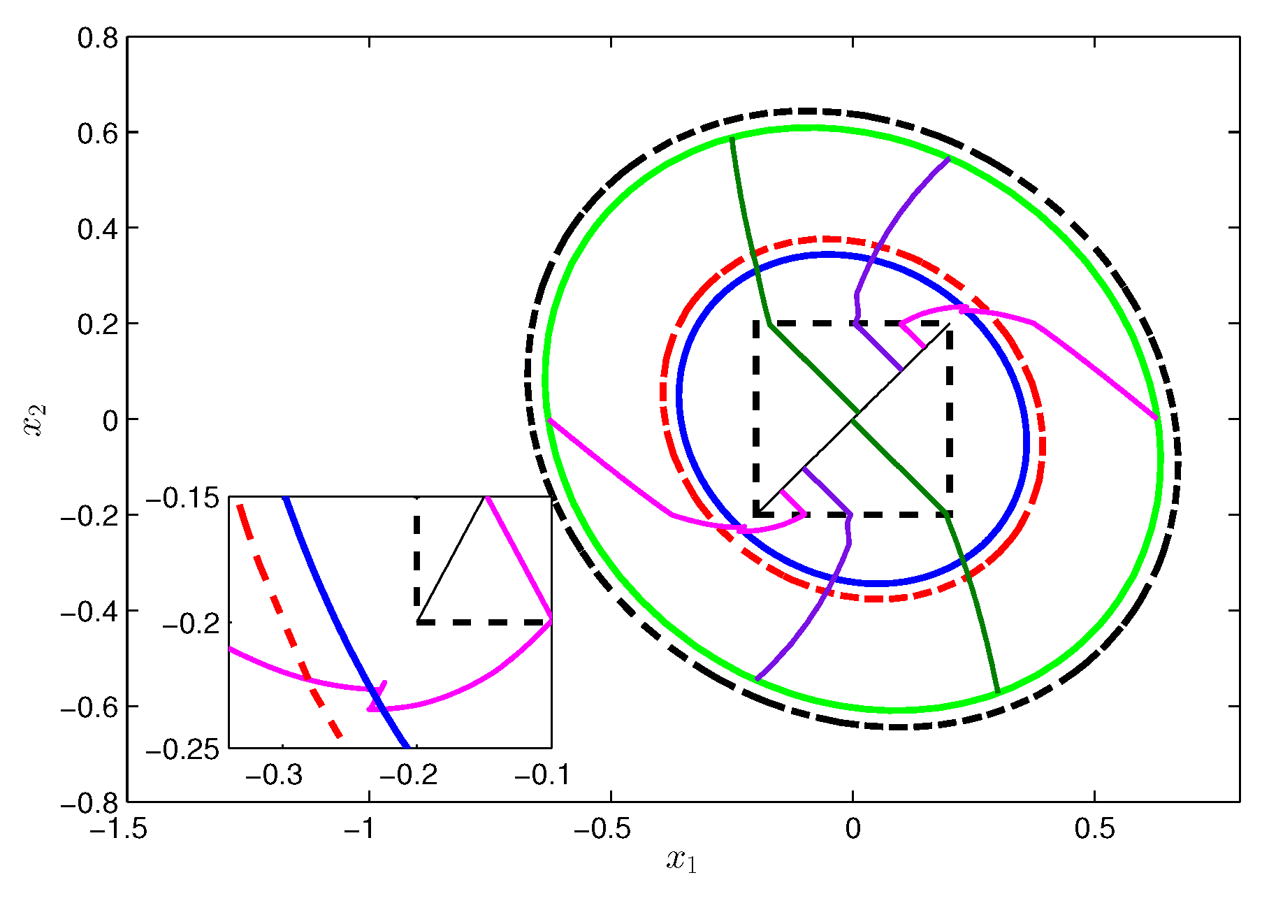
is a square with the origin as the center and 0.4 as the side length, shown as the dotted square in
Figure 4.
The variable design procedure is summarized as follows:
Step 1: Let , z defined in (39) as , and the variables in Lemma 3 as and .
Step 2: By solving the LMIs (31)–(35) and (39) by using matlab’s LMI toolbox, we get
,
. Then, we can easily get
Step 3: By a simple calculation, one knows that , and thus, , which guarantees the establishment of (10). Similarly, we can get and , yielding . Moreover, and hold. Assuming that and , it is easy to see that , and , and thus, .
Step 4: To ensure (36), we need to pursue a suitable . For the quantizer defined in (40), it is not hard to see that . Then, in (9) can be chosen as . If we let , we have , and thus, (36) holds.
Step 5: If we let
, by using the values of
and
, then the ellipses
(blue solid line),
(red dotted line),
(green solid line), and
(black dotted line) are shown in
Figure 4.
Step 6: We set
to meet Condition 4. For the initial states located at
with
, the state trajectories of the closed-loop two-tank system are shown as colored polylines in
Figure 4.
Analysis: From
Figure 4, it can be observed that (1)
,
if
satisfies Condition 1 and that (2) one can find a finite time
satisfying
. Then, Theorem 1 is testified. Moreover, from the subfigure in
Figure 4, we know that the state trajectories will never leave a slightly larger intersection
rather than
upon entering
.
Since and when the control input , the state trajectories will eventually approach the dotted line instead of the origin once they reach the region , in which , and thus, .
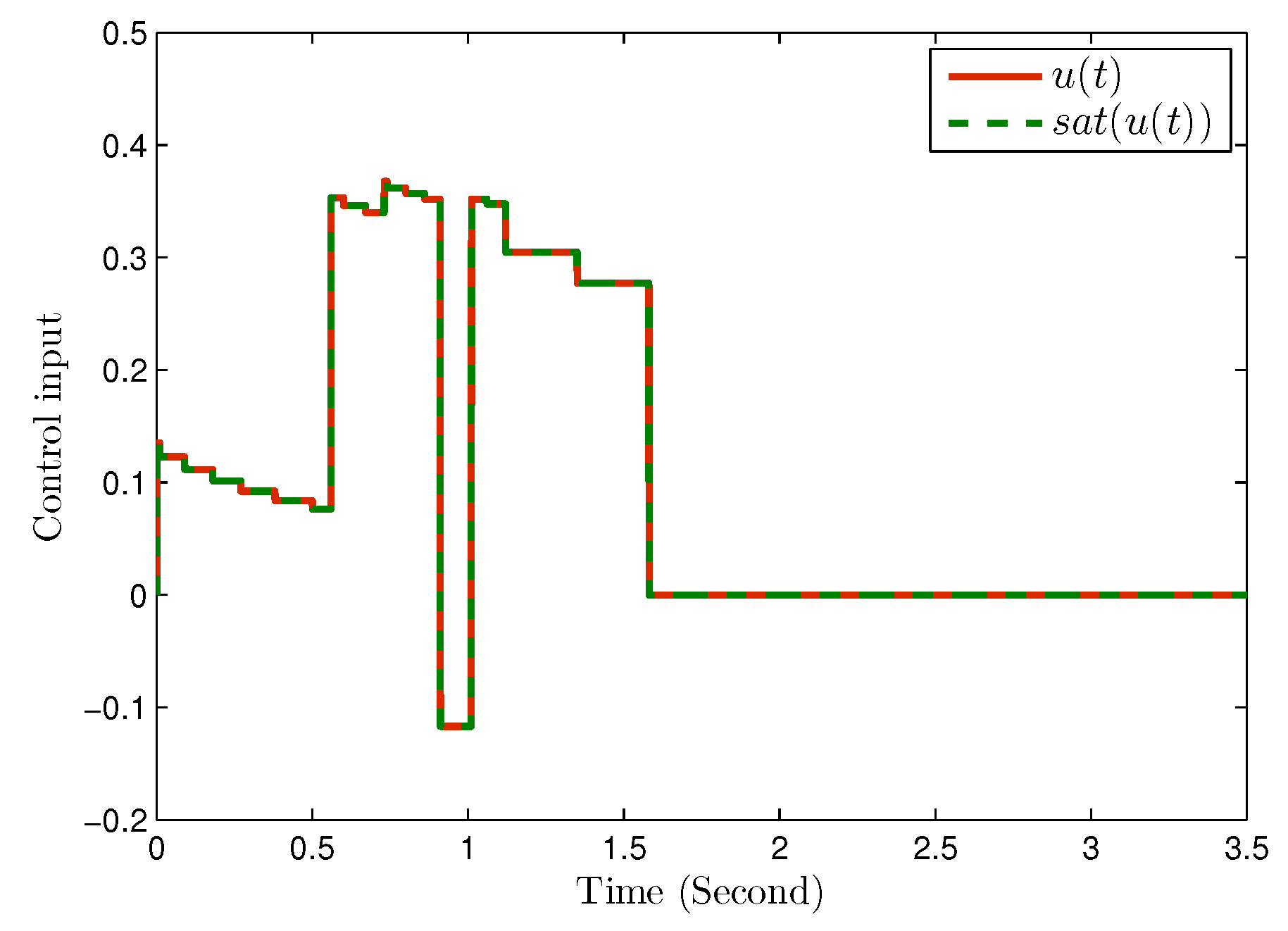
Step 7:
Figure 5 presents the control input and the saturated control input. Obviously, saturation has no influence on the value of control input under the above variables, i.e.,
.
Step 8: To demonstrate the effect of saturation, for the initial state located at
with
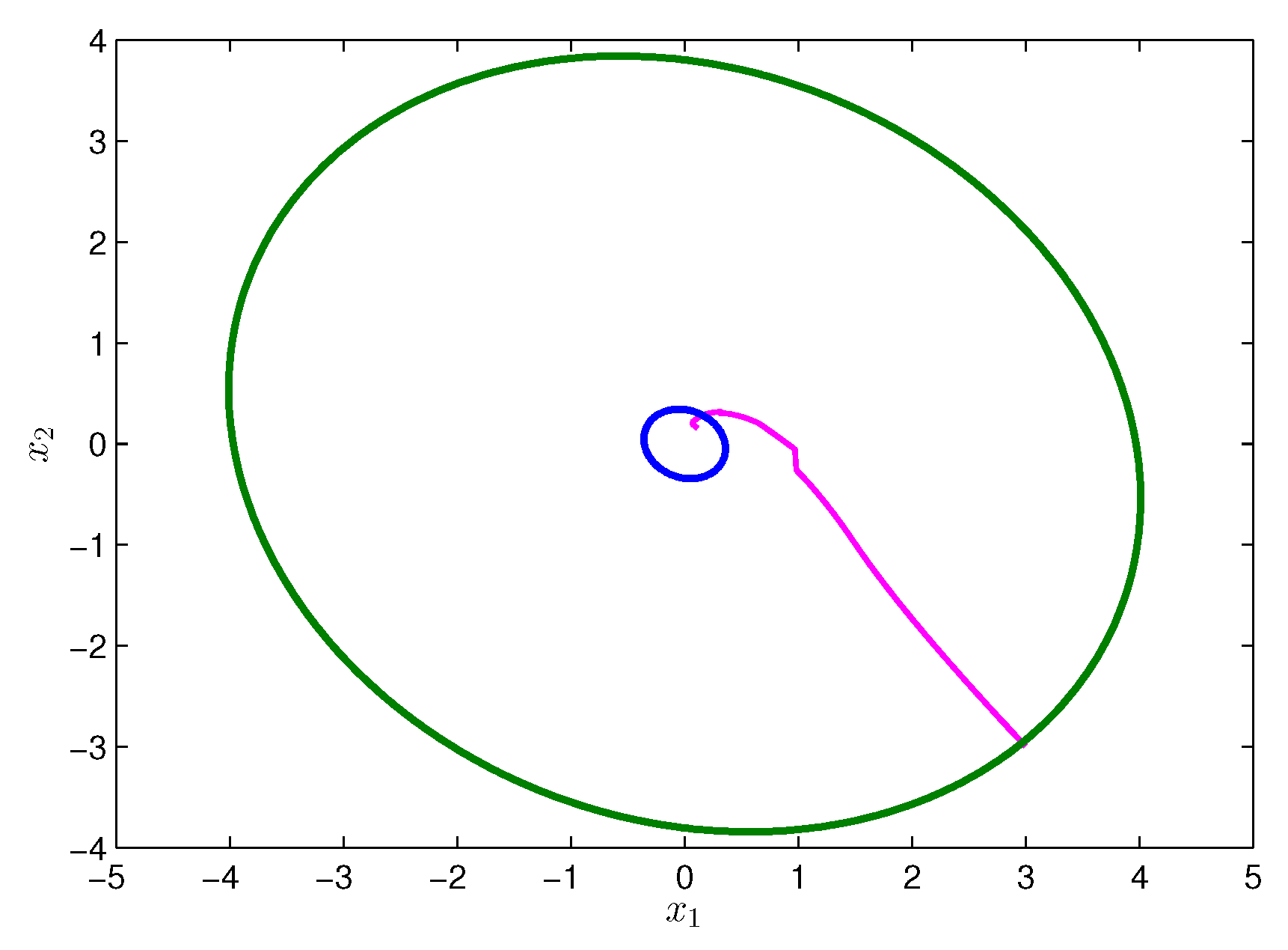
, the state trajectory of the closed-loop two-tank system is shown as a pink polyline in
Figure 6, in which the ellipses
are denoted by the blue solid line and
is denoted by the green solid line. The corresponding control input and the saturated control input are shown in
Figure 7. We can see that under the influence of saturation (i.e.
), the closed-loop system is still stable.
Comparison: To compare the results obtained in Ma et al. [
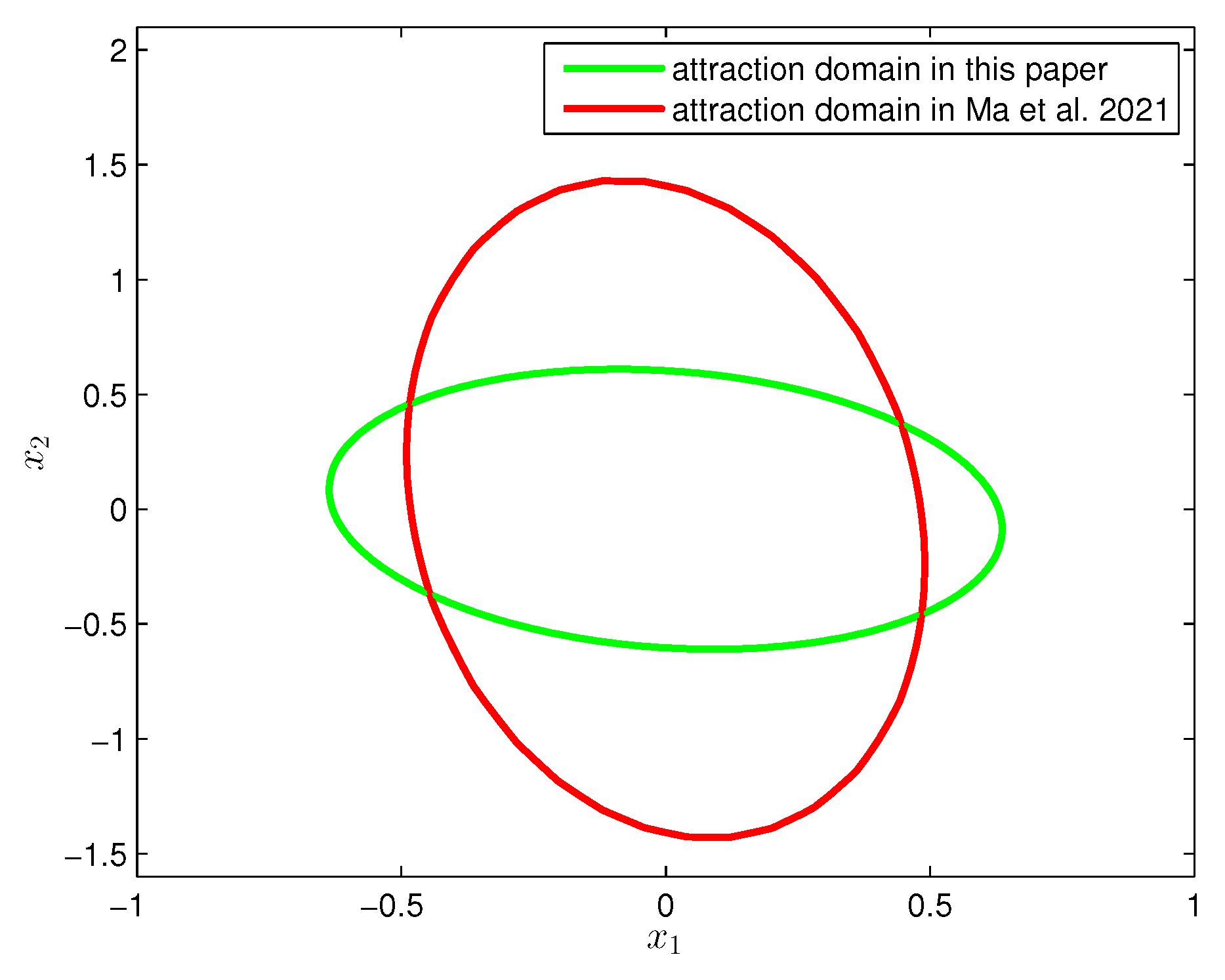
31], the attraction domain obtained in our paper (green solid ellipse) and that (red dotted ellipse) obtained in Ma et al. [
31] are given in
Figure 8. From such a figure, we can see that the attraction domain obtained in this paper is smaller than the one in Ma et al. [
31] due to the extra effects of sampling and data quantization. However, compared to the continuous data transmission adopted in Ma et al. [
31], sampling can significantly reduce the volume of data transmission. In addition, the introduction of data quantization ensures that the algorithm proposed here can be used in the networked switched systems. It is worth mentioning that the domain attraction in this paper is not much smaller than the one in Ma et al. [
31] due to the suitable design of quantization rules and
in the Lyapunov function.

