Review

Related Standards and Certifications in the Architecture of Service-Oriented System in Welding Technology: A Systematic Review

by
Bálint Molnár
1,
József Szőlősi
2,*,
Attila Gludovátz
3 and
Mátyás Andó
4
1
Department of Information Systems, Faculty of Informatics, ELTE Eötvös Loránd University, 1117 Budapest, Hungary
2
Savaria Institute of Technology, Faculty of Informatics, ELTE Eötvös Loránd University, 9700 Szombathely, Hungary
3
Department of Program Theory and Software Technology, Faculty of Informatics, ELTE Eötvös Loránd University, 1117 Budapest, Hungary
4
Institute of Computer Science, Faculty of Informatics, ELTE Eötvös Loránd University, 1117 Budapest, Hungary
*
Author to whom correspondence should be addressed.
Math. Comput. Appl. 2025, 30(2), 38; https://doi.org/10.3390/mca30020038
Submission received: 9 February 2025 / Revised: 28 March 2025 / Accepted: 29 March 2025 / Published: 31 March 2025
(This article belongs to the Section Engineering)

Abstract

:
IT (Information Technology) support plays a major role in CPSs (cyber-physical systems). More and more IT solutions and CIS (complex information system) modules are being developed to help engineering systems to a higher level of efficiency. The different specificities of different technological environments require a very different IT approach. Increasing the efficiency of different manufacturing processes requires an appropriate architecture. The Zachman framework guidelines were applied to design a suitable framework architecture for the welding process. A literature search was conducted to explore the conditions for component matching to a complex information system, in which advanced data management and data protection are important. In order to effectively manage the standards, a dedicated module needs to be created that can be integrated into the MES-ERP (Manufacturing Execution System-Enterprise Resource Planning) architecture. The result of the study is the creation of business UML (Unified Modeling Language) and BPMN (Business Process Model and Notation) diagrams and a roadmap to start a concrete application development. The paper concludes with an example to illustrate ideas for the way forward.

1. Introduction

Since the beginning of the 21st century, our technical life has undergone a dramatic transformation. As history of technology shows, the social demand for economic change has always sought efficiency. The first and second industrial revolutions brought unprecedented technological innovation until the third industrial revolution. Higher levels of automation appeared in industry and complex manufacturing systems were developed to support computing. First in larger companies and later in small and medium-sized enterprises, there is an intense interest in the conditions for building complex CPSs (cyber-physical systems) [1,2]. The market economy is being transformed, with a focus on customer needs, creating a highly competitive environment across industry [3,4]. In the 2000s, we reached a stage of development where the next goal became to achieve autonomy, although the technical conditions for this are not yet at the industrial level of the time. In the years since then, the development of IT (Information Technology) has not stopped. In fact, it has accelerated, as the results of the intelligence research are emerging, which, when applied in industry, promise to yield high returns. The need to raise production standards requires national, international, and economic community coordination, e.g., the European Union’s digital agenda, but equally, in all advanced economies, considerable resources are devoted to innovation and research projects [5,6]. Intensive research is being carried out in the areas of networking, data-driven manufacturing, neural networks, and software engineering.
The launch of a number of research projects today continues to demonstrate that new knowledge about Information Technology is needed and is being applied in newer and newer industrial areas to achieve the desired impact [7]. The use of complex information systems in companies is also not new. The evolution of these systems has been rapid from the 1980s to the present day. Compared to the initial MRP (Material Requirements Planning) designs, today’s information systems are, in fact, composed of a wide variety of software components, the combined use of which, due to the complexity of business processes, can only be implemented through proper architectural design. System design activities are now carried out using software-based tools. An enterprise system is composed of many business components, but the specificity of manufacturing companies is that production management is a very strong pillar of the system. The previous production model is shown in Figure 1 below.
The diagram shows the operation of a production technology system. On the left are the inputs to the system which contain the input conditions of the system in response to the otherwise hectic market processes. In a technology-independent interpretation, manufacturing processes always proceed according to this principle, since the control and regulation feedback processes are both important. These are indicated by short blue arrows in the diagram. In the analysis of control, the focus is on plans, standards, specifications, and production parameters, since these, even as external factors, have a major impact on the production system. Consider the regulatory approach to the product life cycle. On the output side, in the classical sense, we can see the results of processes, not always in a positive sense, as wear and tear is fully applied to the production assets and is accounted for in economic terms. For many companies, the feedback of results is already out of date, which means that the actual efficiency is not reflected. In contrast to a Figure 2, a modern approach also describes an enterprise production system that provides a much clearer and transparent picture of technological processes. At its core, the system is based on a pyramid principle of effective interaction between MES (Manufacturing Execution System) and ERP (Enterprise Resource Planning) according to the automation pyramid in the ISA-95 and IEC 62264 approach [8,9]. The complex subsystem of MES includes all manufacturing factors and control processes, allowing manufacturing processes to operate in a predictable manner. Process inputs and outputs can be implemented in the enterprise framework and are usually linked to the framework in a modular way. This is particularly true in the case of technologies such as welding and related technologies, where complex thermal processes result in manufactured parts and structures.
Our research in the literature has shown that companies where CIM has been considered as the driver of manufacturing efficiency have achieved significant returns, which have been credibly published after 10–15 years in metrics such as productivity gains of 40–70%, manufacturing lead time reductions of 30–60%, and finished goods in process of 30–60%. In addition to all this, it can also be stated that the development of supporting areas such as IT components in cyber-physical systems is essential to achieve the next level of efficiency improvement [10,11,12,13,14,15].
On a daily basis, production can be designed according to the recommendations of a number of standards for such technologies, and therefore, the validity of the relevant standards is essential to achieve the desired quality. An example of this is the correct choice of electrical parameters (current [A] and voltage [V]) for arc welding procedures, which primarily influence the shape of the weld (weld width and fusion depth). The correct design of welded seams is subject to a standard limit value. EN ISO 6520-1 and EN ISO 5817 standards for steel (nickel and titanium alloys) can be used for this purpose. The composition of welding shielding gases also has a great influence on the shape of the weld. Therefore, the EN ISO 14175 standard for the use of welding shielding gases is equally relevant. The choice of input material and the welding process implies a number of technical recommendations in which the standards help technologists [16,17].
Standards provide a variety of information (textual, parametric, possibly pictorial) to support daily technological tasks. However, engineers are often confronted with the need to monitor the periodic renewal of documents, which is a major part of engineering tasks in practice. To solve this problem, the creation of a documentation system engineering module could be used to devote a large part of the engineering activities to practical task solutions; this is a secondary goal for the time being, but the module should also take into account a future machine learning operational nature, i.e., it should be available as a preparation for machine-learning-based decision making. Current research on technology standards does not address system engineering solutions to handle the real-time retrieval of information from technical recommendations.
In this paper, we review the literature and design principles that can be used to create a software component that can be used to subsequently address the standards and other directives in force, even in an autonomous manufacturing environment that supports manufacturing with relevant standards. The first step is to create an architecture that can accommodate the concerned component. The goal is to build an enterprise and software architecture that incorporates a variety of unstructured data and information. The architecture building blocks provide a meta-level structuring that allows services to access the information they need. Services are developed according to the principles of SOAs (service-oriented architectures) and microservices [18]. A development roadmap will be published, with the ultimate goal of preparing the creation of a documentation management (SysTanD—system for standards and directives) component, which will be published as a result of our next study.

Software from Major Vendors

The largest software developers in the world are SAP, Oracle, IBM, Dyntell, Pharis, and Forcam, all of which have made tremendous progress in the last two decades [19,20,21,22]. Since the advent of CIM, software vendors have been developing increasingly large software components with the largest ones having achieved significant commercial success. SAP AG (Systemanalyse und Programmentwicklung Aktiengesellschaft) is one of the four major software vendors in the world and has become the most prominent and market leader in the development of ERP frameworks. The SAP architecture assumes cooperation between the following elements according to [23]:
  • User interface layer: It includes user interfaces such as a SAP graphical user interface, which is client software installed on the user’s workstation [24]. SAP S/4HANA provides the SAP Fiori user experience and interface, accessible through a browser, as an alternative to SAP GUI [25].
  • Application layer: This layer contains the servers that are responsible for executing the intended business logic. This layer uses the proprietary SAP ABAP (Advanced Business Application Programming) programming language [26,27].
    In addition to ABAP, the SAP HANA environment supports the use of various programming languages, including SQLScript. The SAP Cloud Application Programming Model (SAP CAP) is a framework that integrates open source and SAP tools and technologies, consisting of tools, languages, libraries, and APIs [28]. The application layer consists of SAP ERP Enterprise Resource Planning, SAP CRM (Customer Relationship Management), and SAP SCM (Supply Chain Management), together forming the Business Suite applications. SAP HANA, an in-memory database, provides the single database as the underlying data architecture and serves the Business Suite [29].
  • Database layer: The collection layer of database systems used to store relevant data. This is for example the case of SAP HANA [30]. In addition, SAP HANA (either cloud or on-premises solution) can connect to various data collections of different data types, for example, Apache Hadoop can be used for Big Data Analytic. Any relational database management system can be connected using standard SQL and database connect interfaces. The external input data can be in heterogeneous data type format, e.g., XLXSX, CSV, XML, etc. [28,29].
  • Integration layer: an important layer for our study, as it provides the possibility to connect modules. An example is the SAP Cloud Platform Integration platform that consists of SAP Cloud Integration Suite, SAP Cloud Data Integration Suite, etc. [28]. As data analytics has become a core functional service of business information systems, also known as ERP systems, new roles have emerged, such as data curator, data architect, and data engineer, alongside the traditional database designer and data administrator.
Figure 3 shows an example of an SAP architecture diagram. The left side of the diagram shows the architecture of SAP GUI technology. SAP GUI technology means that the end user can communicate through various dialogue boxes using graphical screen applications. The information in the applications is presented to the user in the ABAP language or through display layer programming. When an ABAP program is called, the ABAP environment activates the necessary screens at runtime. The database layer uses the RDBMS (relational database management system). Figure 3b shows a holistic data management, memory-centric platform solution for SAP HANA, designed with the developers’ ultimate goal of making data management fast and efficient enough for business processes. The necessary hardware elements for fast data management are included, i.e., multi-core CPU (central processing unit), SSD (solid state drive) backups for adequate performance of SAP HANA database management. Data storage and processing is also implemented using SAP HANA Studio, shown in grey in the figure. The core of its operation is that the sessions and connections of the database clients to the system are created and managed by a connection and session management component. Communication between the client and the database takes place via SQL (Structured Query Language) script (a powerful scripting language), MDX (Multi-Dimensional eXpressions), the query language for OLAP (Online Analytical Processing) databases, which is closely related to BI (business intelligence) data transformation, and FOX (Formula Extension) language.
Although it is one of the largest in the world, there is a huge opportunity for smaller start-ups to catch up with the market leaders by developing specific software to make it easier to use and to manage data more securely and quickly. Perhaps the developers of MES software components are closer to the subject of our current work. However, it is a huge challenge—perhaps even impossible—to create a software ensemble that works correctly in all technological areas immediately after installation. Because even manufacturing companies using the same technology have different technological processes, frameworks can only be functionally tailored. The Oracle software architecture is shown in the Figure 4 below. The figure shows the structure of ISA-95, i.e., the four levels of Field-SCADA-MES-ERP. Note that while the ERP is implemented with SAP in the figure in the previous discussion, it is not part of the Oracle system. The Oracle helpdesk sites publicly explain the architecture of the MES system, which shows that the process preparation processes take place within the Oracle Process Manufacturing block with four components: Variable Ingredient List, Product Instruction, Flexible Routing Operations, Scalable Recipes. The manufacturing components are fed into the MES core through the Advance Supply Chain component. Operations are controlled by the Manufacturing Operation Center module.
The basis for the development of our study was the fact that we have not yet found a software product that can handle the management of standards and directives specific to welding, but more broadly to any manufacturing technology, at the MES level. There is no doubt, however, that the huge amount of development work in this area will lead to new developments in the near future, because the continuous monitoring of standards is of key importance and the management of documentation, which is currently achieved manually, must be able to support autonomous manufacturing systems in the future.
Another reason why we have carried out system research and development and a software experiment is that Digital Transformation is a must for SMEs (Small and Medium Size Enterprises) [31]. A cost-effective solution and a technology solution that is plausible to implement should be found, based on a solid theoretical and formal background.

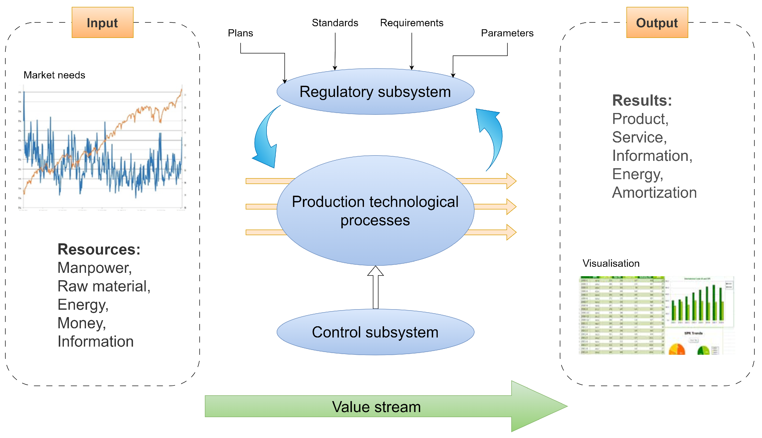
2. Welding Technology as an Information System

The manufacture of welded structures, within the system of technologies, is a significant area, since, due to its complexity and the adequacy of material transformation processes, economic aspects must necessarily be taken into account in the production of welded structures [16,32]. The production of welded structures within the system of technologies is an important area, since due to its complexity and the adequacy of material transformation processes, economic aspects must necessarily be taken into account in the production of welded structures. The production of welded joints is a complex process where the existence of applicable standards is a key issue. All manufacturing conditions are relevant and must, therefore, be documented to ensure that the welded structure is of the required quality. The complete welding process is generally illustrated in detail in the figure below [33,34].
Figure 5 below shows the general case of the complete welding process, which can be further represented as four separate steps as follows: preparation of production (welding), under welding, following welding, and preparation of transport as an associated logistics processes.
Preparation of production (welding): The availability of the entire process environment is checked at this step, since if any component is not operating at the right level, the entire process cannot be efficient. The MES manages availability, material allocation (workflow assignment), resource management (skilled human resources qualification issues), status information management, and the associated production scheduling machine load against the order. In-process queries to support production planning (status logs). Preproduction documents (drawings, specifications, customer requirements) are also located in this block. A crucial question is whether the welded product is a first piece, i.e., a first sample, or whether it has already been in production. In other words, if it is a first sample, a WPQR (Welding Procedure Qualification Record) is required, which is a complete test report for the sample. This part of the process is therefore not always used, but only for initial samples or periodic tests. For this reason, it is shown in a different, grey color in the figure. Examples: CEN ISO/TR 15608, 20172, 20173, 20174, EN ISO 14341.
Under welding: In the context of tracking operations, the MES assumes responsibility for real-time status monitoring, during which task elements pertaining to optimization are displayed. These elements require a continuous data feed from the field devices, and the process step entails the logging of production parameters and settings, based on the WPS (Welding Procedure Specification). Deviations from these parameters are permissible within the confines of 10%, a stipulation that is also enshrined in the standard. It is imperative that standards are met for the entire process environment, including parameters such as cooling time. The system must also be capable of receiving and logging the results of quality monitoring based on the welder’s self-reporting (self-checking). Examples: EN ISO 15609-1, EN ISO 5817.
Following welding: The subsequent series of post-weld operations in this process step encompasses those that are exclusively necessary to address specific technological requirements, such as plate straightening, surface treatment, and NDT (Non-Destructive Testing). In this regard, the output parameters pertaining to quality can be utilized to inform the subsequent parts’ production parameters, thereby ensuring optimal efficiency and efficacy. The outcome of quality tests dictates the handling of OK, repairable and final scraps. This handling must be conducted separately, both physically and in the documentation. As scrap handling becomes increasingly costly towards the end of the production process, it is necessary to assign repair operations to this process step. Example: EN ISO 17663.
Preparation of transport: Finally, the packaging and transport operations are integral to the technological process. While the overall preparation for logistics may encompass specific operations, this is not typically indicated. During this phase, the MES notifies the ERP of completed production and manages the documentation of any repair work on items that may be returned, for instance, from the customer.
At many levels of control, the objective is the same: to ensure the quality expected by customers and to confirm the safety of production [35,36]. The following sequence of events must be observed: firstly, welders must perform self-inspections; secondly, the first sample must be subjected to WPQR (first sample, then periodic inspections); thirdly, WPS with specified production parameters must be carried out; and fourthly, special NDT inspections must be conducted for defects that are found during visual inspection [37,38], as well as customer requests, for example, for welded rail applications, where a much more complex set of quality requirements must be met, which means more frequent inspections. At the moment, these are mostly decided by people, and each one is linked to a long list of standards. Consequently, IT applications will underpin the information systems of the future by introducing extreme complexity. The objective of this research is to ascertain whether future manufacturing technology systems driven by artificial intelligence applications [39] will possess the capacity to distinctly identify the guidelines that are currently contained in PDF-based documentation. The following Table 1 provides an overview of the components of digital manufacturing. In addition to the main components, a couple of examples are given to illustrate how complex a future cyber-physical system should be [40]. This assertion is especially valid in the context of documentation management, a field in which there is currently an absence of clearly defined solutions for the integration of systems with ERP-MES. Consequently, researchers specializing in I4.0 have issued a call for greater consideration of this issue [41]. It should be noted that several software developers are working on database systems that will be able to handle technology documents in the future. However, the key to their applicability will be their integration with cyber-physical systems under the peripheral condition of immediate data management. The need to move to digital manufacturing is driving the development of document management platforms, which has accelerated significantly in recent years.

Welding Standards

It has been demonstrated that standards (best practices) play a pivotal role in the regulation of the entire welding process. Technology standards and their corresponding recommendations function as the drivers of the manufacturing process, and their significance is such that monitoring changes in standards represents a significant challenge in terms of production preparation. Standards are subject to constant revision; however, since these changes do not occur concurrently, real-time monitoring of standards is required, in accordance with the industry domain of the product being manufactured. To illustrate this point, consider a welded joint designed for use in an aircraft component, which is likely to have significantly different quality requirements compared to other applications. They also contain industry-approved recommendations and parameters to guarantee quality and the appropriate metrics, KPIs (Key Performance Indicators). At the appropriate level of quality management, the following can be ensured: transparency of processes, product quality by reducing of scraps, quality control, continuous improvement by finding bottlenecks, improved professional and working knowledge, reduced production lead time, and increased delivery accuracy.
In the realm of production systems, a pivotal consideration that transcends efficiency is that of quality. It has become evident to industry leaders that customer satisfaction serves as the cornerstone of a company’s success. This principle must be given primacy in all circumstances. For the preponderance of companies, the merits of ISO 9000 certification have become apparent, with the certification process leading to the effective implementation of company processes. This certification encompasses a quality policy and a meticulously designed standards-based management framework. Certification serves as a means for manufacturers to demonstrate their quality manufacturing capability, a factor that has become imperative for customers when selecting a supplier. This confidence is founded on the efforts of independent certification bodies, which periodically audit manufacturers to ascertain their adherence to customer expectations. This principle applies universally to all manufacturers, irrespective of the technology employed. In this study, our focus is specifically on the welding sector, where standard recommendations are widely applicable throughout the entire technological process. Welding technology experts have developed the ISO 3834-1...5 family of standards for welding plants in the ISO 9000 series, which fully cover the description of the overall manufacturing environment, the general requirements of the welding plant, the management of materials, the qualification of welding personnel, the control processes, the involvement of subcontractors in the production, and the quality management documents used.
For manufacturing systems, the shift to a digital manufacturing culture is also a challenge in terms of standards, so our aim is to map this area with an IT approach. These documents are the basic tools used to supervise welding. They contain good practices, experience, correct results of procedures, and limits. Adherence to the recommended procedures is important to ensure proper quality. A wide range of standards (approximately 100–150 pieces) is available for all elements of the whole production process related to welding technology [42]. You need to be very skilled to adapt the latest standards to everyday welding tasks. The standards cover many different things, like the technology used, getting things ready to be welded, the actual welding process, how skilled the welders are, and if the place where the welding is performed is suitable. The requirements of the various disciplines also need to be considered in terms of the quality of the products, since the requirements are not the same for a general structure, railway application, a pressure vessel, or a hall structure. In addition to the applicability aspect, another important issue in the classification of standards is the information they provide. Definitions in standards may be textual, but may also be tabulated numerical values for parameters. In the day-to-day application of standards, the practitioner usually uses a paper-based document or a document with some kind of .pdf extension. When making products using computer technology, these formats will not work. We’ll need to find a way for an algorithm to access the information. As the standards’ procedures and directives are usually accessed via a web-based interface, it seems reasonable to create a web application. This application can provide the documents for manufacturing and can be integrated into the MES software suite mentioned above. For those standards where some technological parameter or limit value related to quality deviation is the information, it should be captured in the implementation of the application in a different way than the textual definitions. As an example, consider the standards ISO 6520 and ISO 5817 for quality deviations of arc welds. The former contains a description of the defect patterns for the determination of the deviations [43], the latter contains a description of the actual method of calculation of the applied limit deviations or a specific limit value [44]. It is worth noting that, due to their practical application relevance, the European and international families of standards are typically taken as a starting point, i.e., their monitoring is the focus. Of course, similarly carefully crafted directives, specialties, and families of standards that differ from these, possibly also applied in other continents, may also be the cornerstones of the task later on. Figure 6 below shows an example of a selection of relevant standards, broken down into quality, sector-specific areas, welding procedure standards. The list is not intended to be exhaustive, as many more areas are covered in terms of the application of standards.
This figure shows how important it is to use standards, procedures, and certifications in engineering. It makes sure that business processes are technology-oriented, and that customers’ main expectations for quality are met when these documents are used in production. It helps people learn more, so professionals can find solutions to manufacturing problems quickly. Perhaps one of its most important functions is to demonstrate manufacturing capability by obtaining/maintaining certifications (e.g., railway standards—ISO 15085; general delivery conditions and technical requirements for the execution of steel structures—EN 1090; pressure vessels—PED) because it measures competency. At the end of the study, a concrete proposal for the development and implementation of the standards module will be made in the form of an implementation plan.

3. Technical Components for the Designing of Architecture

A complete information system naturally consists of many components due to its complex structure. It is the perfect interaction of these that gives the system its functional adequacy. In this chapter, we list the building blocks, sometimes concepts, that are important to achieve the goal of our research, which is to design a specific information system [45].

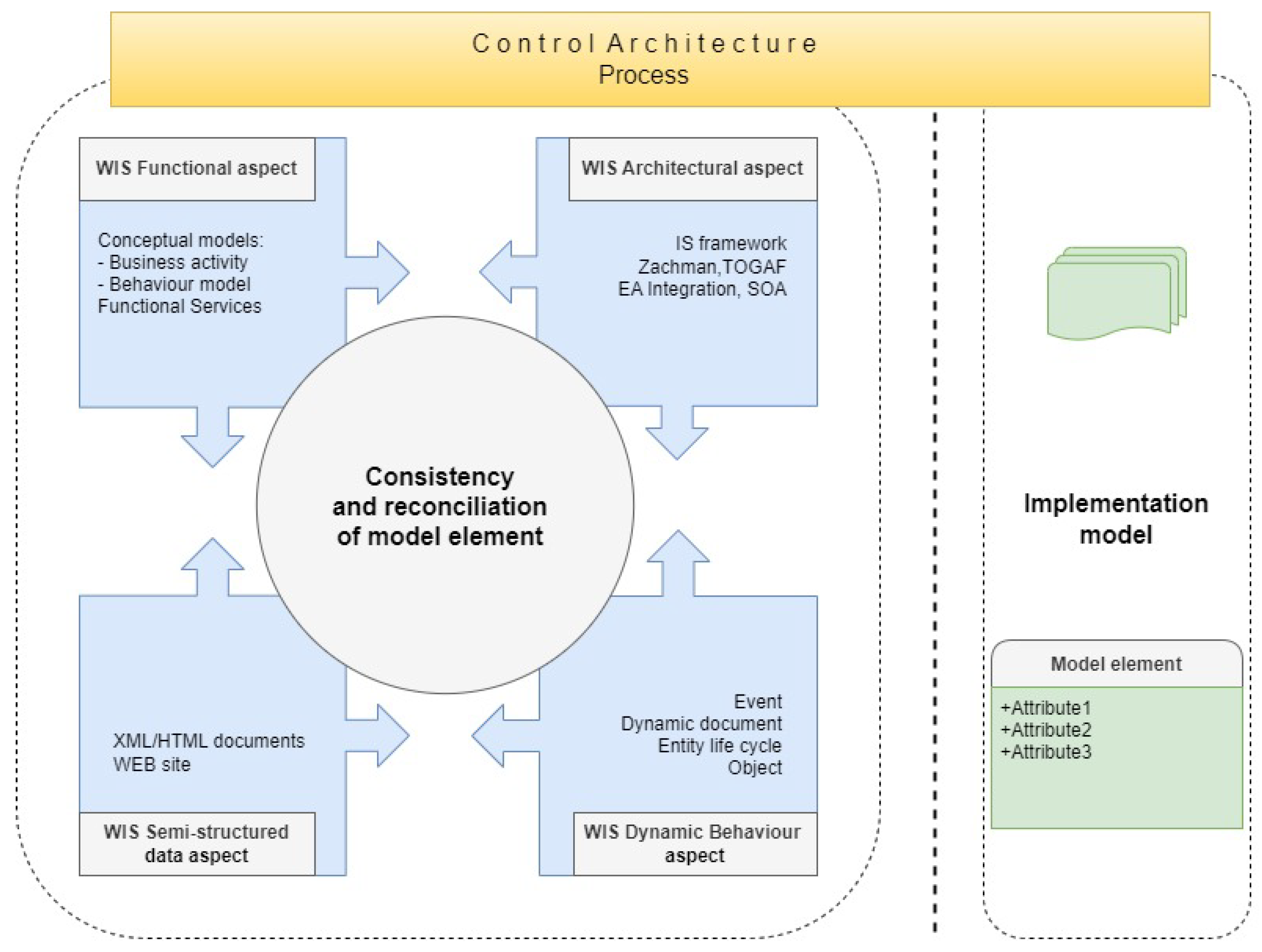
3.1. Operational Framework for Information Systems

The architecture is an important description of a company’s organizational structure and operation, which is in fact a model and shows the interrelationships between the different units in a piecemeal way [46]. When designing an enterprise architecture, frameworks are used to describe the model from different perspectives [47]. Various frameworks have been used for decades to design architectures. The so-called EA (enterprise architecture) frameworks are used to describe architecture work by describing models based on process understanding to define the enterprise layers, but it is particularly important to define the relationships, inputs, and output entities between the different areas. The first significant work on designing financial and organizational systems was published in the 1960s on the initiative of TOGAF (The Open Group Architecture Framework) [48], and by the 1980s, the current set of tools was published and became the standard for systems design methods. It was at this time that John Zachman developed a similar methodology for defining information systems [49]. Five years later, he refined the original ideas in another study [50]. In the following decades, the basic methods for creating frameworks are already emerging at governmental levels and are increasingly defined as an important tool to be used, with the result that the design environment for enterprise architecture and information systems is no longer at all different. The subject is being intensively addressed both within the NIST (National Institute of Standards and Technology) in the United States, but not exclusively, with studies also appearing in Europe, for example with the support of the BCS (British Computer Society). Thus, in 1992 [51], and then in the early 2000s [52] and in 2016, significant studies were carried out to improve methodologies [53].
As you can see, designing with a framework has now become essential. It is a modeling tool that is extremely important for the design of information systems because it is efficient. Table 2 shows the application’s conceptual framework. The cells of this table show the different models that define the components of an information system. The definition of system components by models, i.e., their description using different modeling languages, is well-defined and has been widely used for about twenty years. Modeling languages are not without a mathematical background; for example, they are sufficiently represented by the tools of graph theory [54]. In the rows of the table, you will find the perspectives on the system and in the columns the questions on the different aspects of the information system, as follows: What are the system data and datasets from processes? How does the system work and processes? Where are the system activities? Who is a participant, user, or end-user in the process. When in the process do events occur? Why this is the system element run? The framework helps to keep all aspects of the system in focus. However, the web applications require additional considerations. Thus, the columns in the table were supplemented with the model view, covering both the static and the dynamic nature of the system. The ultimate goal of the application is to represent together a unified whole of the different aspects of a complex process system described by models. To achieve greater efficiency in enterprise operations, you need an architecture that can handle rapid business change. To reach this, flexible information systems are used, but it is important to bear in mind at the system design stage that changes to system processes can be extremely rapid, so we can manage them in some kind of enhanced framework rather than the classic system architecture. This is the purpose of the CIS (Cognitive Information System), the elements of which are shown in this table. By predicting the occurrence of business events, the system’s processes can be re-engineered, giving the information system and process management greater flexibility. This makes it more efficient to detect errors and identify new business opportunities [55].

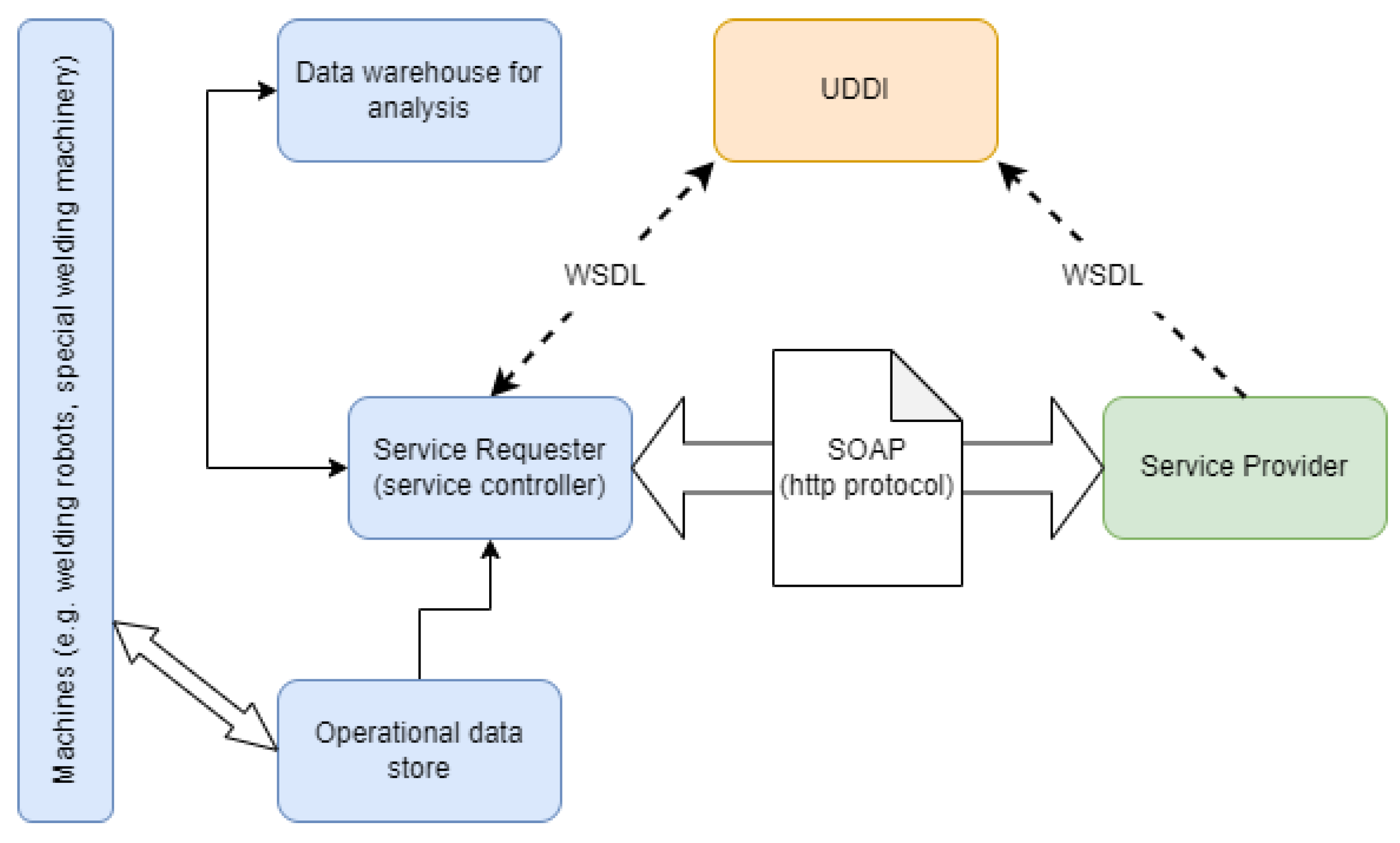
3.2. SOA (Service-Oriented Architecture)

The emergence of service-oriented architectures is closely linked to the spread of customer-centric thinking. Shortly after the middle of the last century, a new approach based on a kind of supplier–customer relationship began to emerge, where the customer’s needs are at the center and the quality of service must be adapted to these needs. There are many early examples where the market leadership of large companies depends on serving their customers to the full. It is through this idea that we are moving towards the creation of SOA, in which systems that support business functions are perfected. SOA is a set of methodologies that exploit the support potential of IT from a business perspective, i.e., it uses business processes as components of information systems to provide them with the flexibility inherent in information systems, as the prioritization of business events results in a constantly changing environment [56]. For this, loosely coupling components is the right direction, which is also a function of SOAs [57]. Another function mentioned in the literature is the service-based approach. These features actually provide the flexibility, re-usability, and interoperability benefits of application components [58,59]. To understand how a SOA works, we need to see the benefits of the Internet and web activities in general. Just as there are many benefits of web applications in any area of our lives, a complex business system can take advantage of these benefits [18]. In the following, we will look at the benefits of web subsystems, as service-oriented architectures and web services are now the same in our approach to the technology environment [60].
For our research, we have reviewed a number of scientific papers publishing new developments and their results. An academic paper has been published on WIS (web-based information system) applications and its benefits [61,62], where WIS is presented as an XML-based (eXtensible Markup Language) entity that works closely with other information systems, and in contrast to other web applications, it supports business processes and databases with unstructured data much better. Figure 7 shows the perspectives that should be brought to the forefront in the design of web-based systems [63].
It is also worth looking at web-based workflow management components, whose development is becoming increasingly popular with architectural designers, as they can handle complex data management. One such iTask application is shown in the following paper [64]. However, other publications also discuss the benefits of information systems [65,66].
For an integrated SOA to work, transparent processes are needed, as this is a prerequisite for any information system development. Business processes can be understood not only in financial systems but also in different organizational systems. The operation of a company is extremely complex, as many different modules need to work together to achieve the desired KPIs. Designing or possibly reengineering business processes is a key issue in designing an efficient system [67,68,69].

3.3. Data Management

Of course, the very need to be able to use data to make decisions is schematically formulated [70,71]. In a more understandable and more sophisticated formulation, data that are in the right format and capable of carrying the right information are what helps systems to function. These relevant data are transformed and cleaned in the data preparation process [72], often in so-called data warehouses, and can be prepared for storage in database management systems. It is for this complex preparation process, i.e., the loading into a data warehouse, that the ETL (Extract-Transform-Load) method was invented, in which, among other things, data are processed in certain syntactic process steps. A possible design of the service call is shown in Figure 8 below. A subsystem specifically designed for the data exchange application manages the process. The service caller initiates a call request and then, after checking the message content from the different service providers, the web application will retrieve the service requested by the caller. The message exchange is XML-based. It is important to note that the data exchange subsystem also performs a content inspection operation [73].
The development of data storage issues is central to the development of a well-functioning production information system. Data availability alone does not meet the needs of today’s industrial users, as in most cases, the diversity of data requires data science methods to produce appropriate data structures. The data come from field devices on the one hand and from external providers on the other. These include relevant parameter recommendations in various standards (in case of a welding area, it is mandatory to use these standards). These standards are revised from time to time as information from “best practice” and experience is incorporated into the recommendations. Newer versions of the standard are available from the service providers. In this case, we can implement a web service, typically using XML or a common type of XML called SOAP (Simple Object Access Protocol). Messaging parties have been using the supporting HTTP (HyperText Transfer Protocol) messaging protocol since the early 2000s. A very useful idea for implementing virtual repositories for data storage is in the publication. The messaging is performed using WSDL (web service description language), using UDDI (Universal Description Discovery and Integration) [59].
In recent years, there have been compelling arguments for the benefits of using cloud-based systems. Beyond the fact that cloud technology is capable of replacing local IT systems to some extent (with all its cost implications), there is a growing demand for modern systems to perform data science activities related to data management in the cloud. However, many modern system designs now use computational methods that do not take place in the cloud, but close to the data sources, at the edge of the network. The upgrade was necessary to make reasonable use of bandwidth and actually reduce response times. Thus, it is now widely used by system designers in distributed computing systems. Recent patents and several notable studies have been published on the subject [74,75,76]. In some cases, edge computing and fog computing have the same meaning, but it is worth noting that this is true when the system used is small-scale and can be understood as a separate layer for larger systems.

3.4. Interface, Platform Perspective, and Its Cybersecurity

Recently, more and more studies have been published on the digital representation of complex manufacturing systems. Among these, there are a good number of software applications that are capable of managing the entire technological sequence of steps. Of course, this software has a user interface that is able to operate the software functions. Imagine software that provides an optimal “tuning” for the given welding task. Step by step, we first manually enter the input data, but obviously, in an autonomous environment, the system controller “should” be able to select the process parameters in the future.
Service-oriented architecture can support business and enterprise processes efficiently. Software support is a collaboration of loosely coupled software services, based on the creation of operational models. Operational models describe business objectives (e.g., data storage, data transmission, data transformation) precisely and SOA metadata plays a key role in this. In IT terms, a service is actually the operation of an interface. Loosely connected entities communicate via protocols, but otherwise via SOAP messaging (Figure 9).
A general example of this message exchange is shown in the code below.
Mca 30 00038 i001
The implementation exploits the potential of the SOA Integration Appliance [77]. The following platform implementations have been tested in the course of this exercise. The detailed platform taxonomy under consideration can be found in Table 3 [78]. IT security of the system should be a particular focus. There are various security recommendations in the relevant standards, and deep learning algorithms are now able to keep your system running smoothly [79]. IT security is also an important design consideration in our system design.
Achieving autonomous production requires a number of tasks that can be identified from several angles. However, development work is already showing that full automation of certain process steps is not possible without major system changes. This problem also affects those business process elements that cannot currently be implemented without human intervention, simply because horizontal integration is not always a given in the business interconnectivity. In other words, it is very important that the processes of suppliers and customers are similar. Future state-of-the-art systems are already focusing on systems engineering solutions that outline the boundary between human and AI (artificial intelligence) activities, while at the same time being able to manage them in a modern way.
One of the most important things to think about in this section is how to keep things safe online. Since the 2010s, the number and intensity of activities on the internet have changed significantly. Cyberattacks against big companies have shown the need for good cyberdefenses that can keep up with attacks. The attacks identified are mostly overloading, data manipulation, and phishing techniques, often with the intention of destroying or obtaining information. Production systems are also not secure in many cases, especially if they are not built on a closed corporate network, but need to build some kind of connection to the capabilities of the world wide web. The most common web interface is SQL injection, which by its very nature is a means of gaining access to a system through a web interface that allows an attacker to access and even manipulate sensitive data. The compromised asset could be not only the IT asset running the web application, but also the entire IT system. A similar vulnerability is the XSS (Cross-Site Scripting) attack, which bypasses the system’s policy to spoof the system’s authentication protocol. DDoS (Distributed Denial-of-Service) attacks can also cause major damage. These attacks are designed to overload the target system’s resources, preventing users from accessing system information and services because the system’s resources are busy with the attacker’s service request. In addition to the fact that the non-profit organization OWASP (Open Worldwide Application Security Project), which summarizes vulnerabilities, recommends increased user protection, i.e., technical solutions for two-step logins, card access, it is also necessary to strengthen cyberdefense from the algorithm side. Artificial intelligence applications that can distinguish normal data packets from compromised packets by applying data science techniques such as anomaly detection are now available. The primary step in addressing the issue is to undertake real-time monitoring of the data and analyze network traffic. The differences between normal data packets and those that have been manipulated are analyzed by observing patterns, even using neural networks. Reference [79] illustrates this solution.
A data packet or message coming through a web application is sent to a decoder. The data are prepared for the machine learning module, which performs a comparative analysis using the samples. Data preparation must take into account the size and complexity of the data packets. Depending on the decision of the module, it either quarantines the data packet or passes it to the users via the local server. The fact of an attack must be recorded and the IT organization must be notified immediately (Figure 10).

4. Discussion

The aim of the research is to integrate the standards management module (own SysTanD module) into the MES-ERP system at the architectural level according to Figure 11. The role of this module is to provide the system with up-to-date recommendations for manufacturing compliance. The application supporting the developed model will subsequently be analyzed in the discussion section. This analysis will focus on a critical evaluation of the literature reviewed and on the application of research methods to design science and software case studies, i.e., research methods. The process development methodology employed is the UML activity diagram and BPMN 2.0.

4.1. Applied Research Methodologies

The solution to our research problem is based on the general design practice of experimental software development. An important aspect of module development is its applicability to cyber-physical systems. Accordingly, the research will follow the guidelines of the Frascati and OECD (Organization for Economic Co-Operation and Development) methodological manuals for development guidelines. Our development complies with the principles that promote the implementation of the Economic Co-operation Treaty of 1961, i.e., the steps taken by the member countries concerned to promote sustainable economic growth. At the same time, considerable industrial experience and, in fact, the expectations of the industrial stakeholders, are leading us in the direction of making the most efficient use of the complexity of the whole system by developing additional modules of information systems in order to achieve full-scale digital production.
In line with design science research, a system design activity was conducted [80,81] (see Table 4). The components that make up the system and software architecture were meticulously crafted, using a design-pattern-based method. Furthermore, workflow patterns were utilized to specify the intricacies of the business processes [82]. The prototype demonstration was assessed by prospective users using the software case study approach [83]. In the following section, the evaluation series of questions is presented in tabular form Table 5 to determine the appropriate architecture. The above list of questions is often used in software, but also in any process development. If a scoring system can be attached to the questions, then the development points can be precisely defined and scaled.

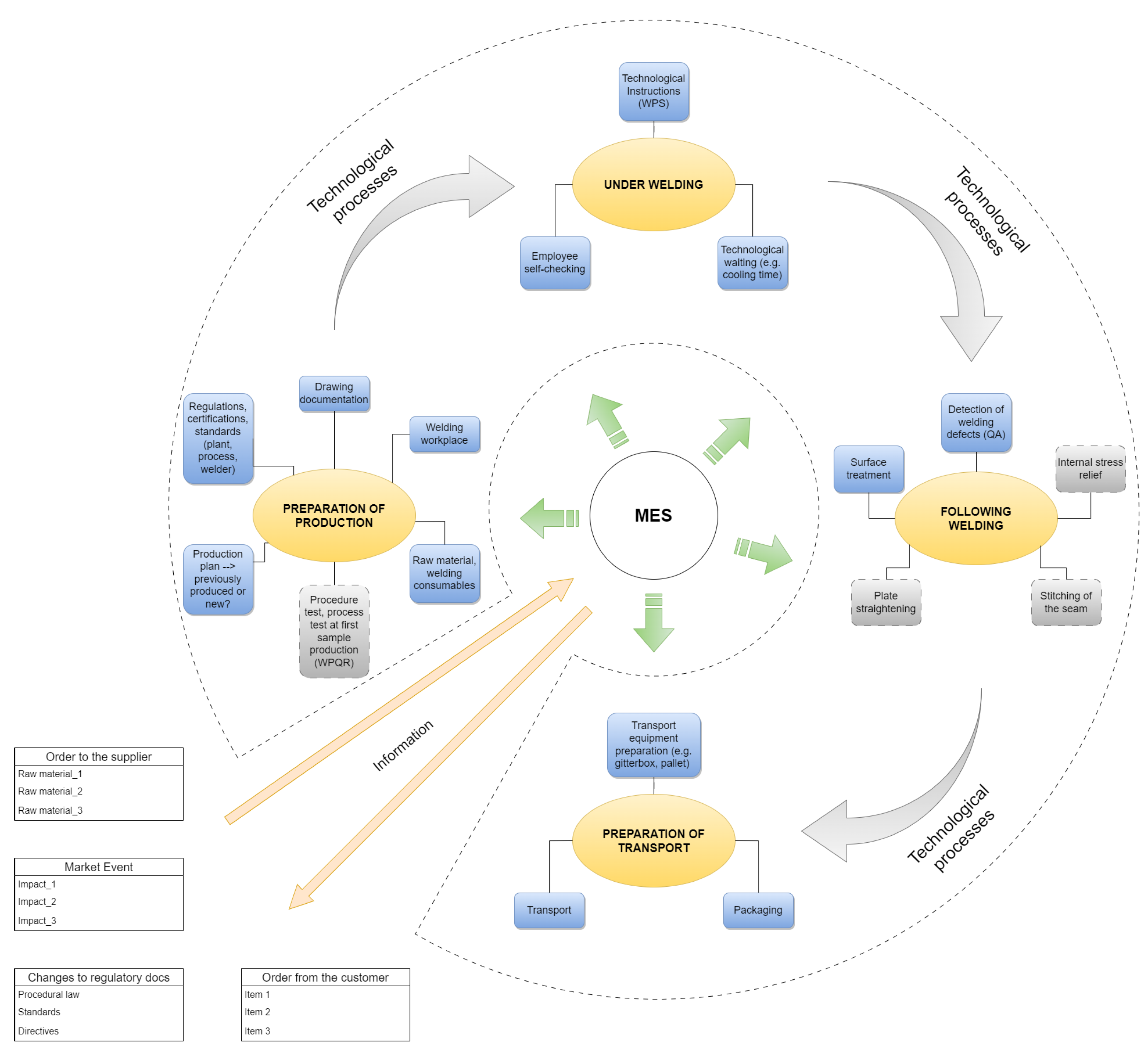
4.2. UML Activity Diagrams and a Process

A UML diagram of the integration of the Systand module into the system has also been created according to the suggestion of [84,85]. Figure 12 shows our vision for this development.
In this part of the research, the main goal is to plan the process of welding which controlled by standards. To reach this result, we made an activity UML diagram to this ETL (Extract, Transform, Load) and data collecting and analyzing process. Unfortunately, the available industrial standard documentation data are not in structured form. Therefore, we need to read the industrial standards and interpret their data. After that, the data transformation process will be started by our web application. During the transformation, we are able to define data variables and initialize their value and measurements. The ERP system’s related data (e.g., HR—Human Resource data) are used to this transformation process as another input. The mentioned HR data are important because the industrial standards determine expectations that someone should be able to solder. To get these data, the web application can reach ERP’s API (Application Programming Interface) via web services. The joint and structured data will be loaded into the MES database or a connected database. In this way, a system integration problem has been solved at the database level.
Thus, the welding process can be started by the industrial standard’s interpreted data and ERP’s selected data. During the welding, the data collecting process is working by the web application continually. These data will be stored in the MES (or the connected) database management system for the further analysis process. Our data analysis tool will be a BI (business intelligence) tool, e.g., Microsoft PowerBI software or a self-developed web solution. With this tool, the analysis (e.g., time series forecasting) results can be shown to the engineers and experts, who can make decisions based on welding process data. For better understanding, we can define KPI’s (e.g., waste rates) that describe the parts of the welding process. In this way, we can make better decisions about welding over time. Validation of the UML conceptual diagram was performed in accordance with [86].
The processes and the application were designed using BPMN, shown in Figure 13. As can be seen in the diagram, business processes need to consider component availability across the entire vertical. As soon as the process starts, the availability of production components is checked. In case a component is missing, the MES resource request transaction is initiated towards the ERP. The request is sent to the relevant ERP module, where it awaits ERP action and confirmation. It is very important that production that has not started due to lack of resources is rescheduled in such cases. Experience has shown that in a company with a wide range of products, it is no longer possible to reschedule production on paper when production events occur. In this case, FMSs (Flexible Manufacturing Systems) use either fine programming or KANBAN, as this is the only way to ensure efficient manufacturing tool capacity. The fine programming of production is a very complex process. As it involves the organization of complex activities for a small number of products, this process can only be handled by a software back-end solution, as the scheduling priorities have to be taken into account during the programming process.

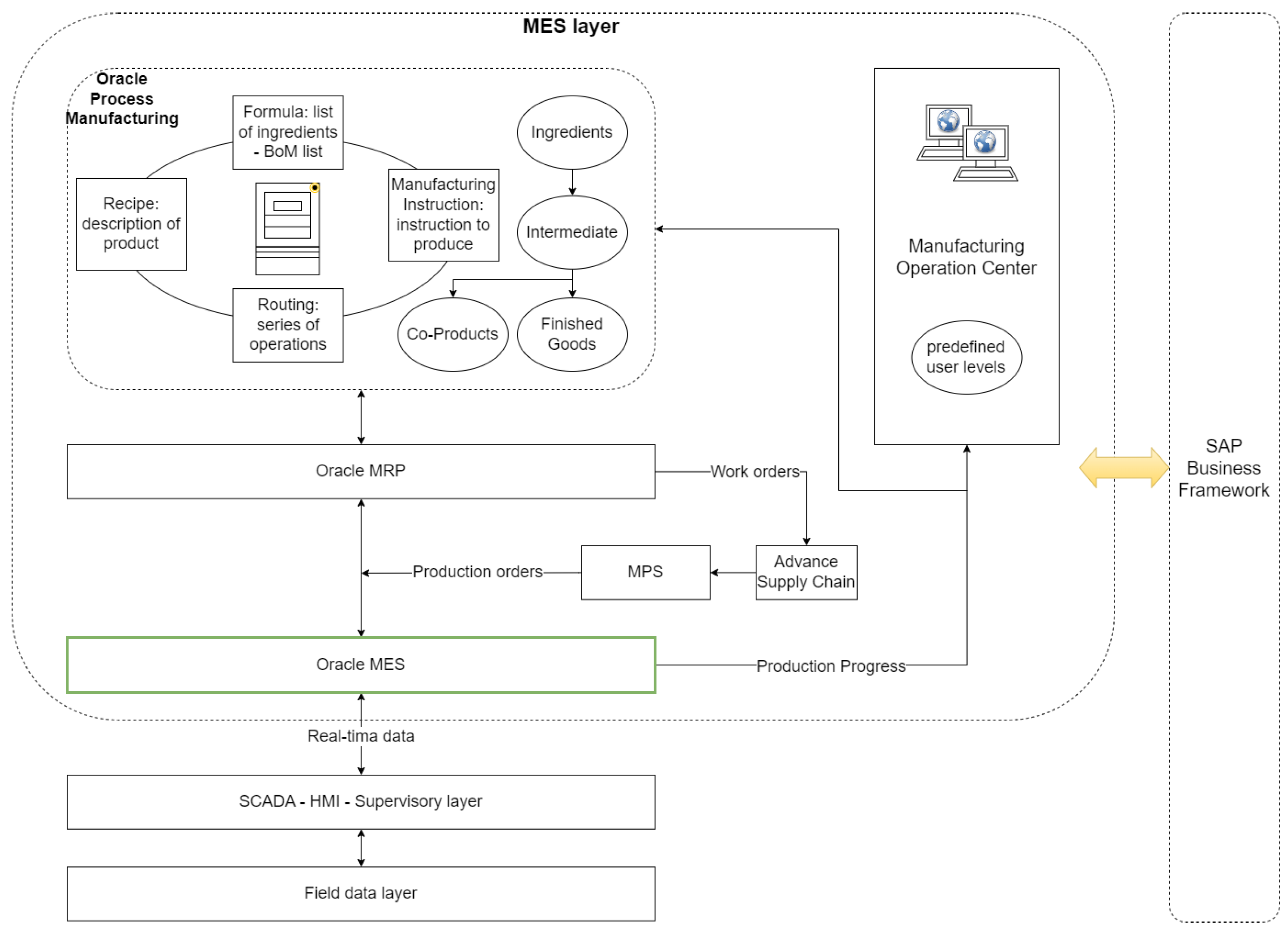
4.3. Technical Solutions for Software Integration

The architecture diagrams for this task were designed according to the TOGAF ADM (Architecture Development Method). Figure 14 below shows the development points of the ADM software development. The TOGAF ADM chart shows the design steps iteratively from phase to phase. The method is highly adaptable to the Zachman framework, but also to other frameworks (e.g., specific government administration). The TOGAF ADM has a well-applied, visually intuitive process based on project implementation steps. In the diagram, the phases in the strategy planning–implementation area are clearly separated. Our task at this point was to design the architecture diagrams for points B, C, D (business-application-technology). Very often, these phases are accompanied by gap analysis, showing the gaps and missing components in the system. The TOGAF methodology has already been discussed in the subsection on frameworks. What made us choose this methodology for the architecture design in any case were the following:
  • It is ideal in cases where the goal is to design an enterprise architecture, or a part of it, that spans all business functions.
  • The framework contains all the building blocks, roles, skills, and responsibilities necessary to make the system work. These are the artifacts, or ABBs (Architecture Building Blocks).
  • It is based on the scenarios of a real organization, on which templates are built, which speed up the design process.
  • Guidelines and technical solutions that may be encountered by the whole organization.
  • It provides guidelines during the design of a highly complex architecture, showing what the gaps in the system are and what should be created in a chronological order of development activities.
  • The reason for the enterprise continuum is that it uses a repository of objects, artifacts, that provide the same interpretation across designs.
  • The TOGAF library contains reference architectures.
Figure 14. TOGAF architecture process.
Mca 30 00038 g014
Figure 15 below shows a simple block diagram of the main business components of preproduction and production management.
The following figures show the most relevant architectures. Figure 16 shows a part of the architecture for the information system and the application development layer. Three levels are distinguished, i.e., the provider level with the web application, the workstation level, and the documentation management level. The figure does not show the interface with ERP; rather, the figure shows the software architecture of the SysTanD component.
In Figure 17 below, we have depicted the process level architecture, where it was necessary to depict the complete MES activity, since we need to know all components from the data query to each process workflow as a condition for correct production preparation [88]. The figure shows the complete MES query-interaction environment, i.e., the Rule-engine and the cache components on separate levels. The DACQ (DataACQuisiton) and DCU (Data Collection Unit) components process the field data of the different equipment at the local level, while the connectivity of the operational, configuration, and office clients should be prepared as a cloud architecture, since the management of the MES is also heavily based on cloud technology.

5. Conclusions

More and more advanced digital tools are and will become available in the industry and in all areas of our lives. The use of all these tools is aimed at reducing our daily losses, and thus, reducing the lead times of processes. Operators in all sectors of industry are also trying to make the most of this principle in order to remain competitive. All of the above forward-looking research reminds us that simply having the data is not enough to carry out I4.0 development tasks. In all cases, it is necessary to use modern IT tools and important IT disciplines. After the design of the architecture, we aim at the actual creation of the SysTanD module and its implementation. Below is an example of our evaluation, and we have included an example of an application of the way forward.

5.1. Example of a Design Concept

A visual interface has been created that displays the manufacturing parameters of the physical equipment (Yaskawa AR 1440 robotic welding cell) in real time [89]. This required complex software components that manage windows and graphical user interfaces, while displaying 3D models and communicating via sockets. The design of the interface required the creation of two applications that interface with the framework. These are called RobotComm and RobotVis. It was necessary to create as simple an architecture as possible because communication between the software components was lengthy in the first phase. The RobotVis program retrieves position data, aggregates it in records and displays it on visual interfaces. The data are saved in .cvs files for later analysis. The RobotComm program establishes the link between the robot and the RobotVis application. The system has a dynamic library .dll loader module, a python interpreter package linked through it, and a communication software library built with the .NET framework.
An example of our ideas is shown in Figure 18 below. The figure shows the visual platform above, with the important identification options on the screen, which can be used to manage several manufactured types and parts separately. Today, there is a clear demand from customers for a unique identifier to be assigned to the product to enable correct production traceability. In the future, the various modules of the MES, which in many cases will be databases of some kind, will run in the background and the records they contain will be retrievable in real time. The latter development is still in the planning stage and has not yet been the subject of any construction work. The data recorded in real time are displayed on the right-hand side of the screen, i.e., instantaneous current, voltage, and motion parameters. The ultimate goal is to be able to feed back production data in this developed digital twin application environment, and thus, to enable a kind of optimal production [90,91,92,93].

5.2. Ways Forward in the near Future

Finally, our study concludes with a development roadmap (Table 6), in which the development points are announced. The first milestone among the points is the creation of MES status levels, i.e., master data. It is important to select the standards with which the standard components can be developed, and it is advisable to select standards that contain a wide variety of information (text, technical parameters, images, etc.). The main components of complex information systems have been reviewed, with a particular focus on data flow issues, where it can be seen that the use of cloud technology is essential. The Zachman and TOGAF frameworks used to define the architecture have been studied. The latter was used to create business-application-technology architectures. One of the main chapters of the study was the issue of cybersecurity considerations, which was only touched upon in broad terms, as the procedures related to these issues are basically taken into account in the design of the software components to be deployed (e.g., cloud technology). One of the most relevant topics of this paper is the emergence of service-oriented architectures in the development of software components. In terms of implementation, it will take a year to develop the right MES connections and the standard component, so it is necessary to set deadlines as soon as the number of project participants is known and the development team is formed.
In our study, we searched the literature for the above implementation tasks. For any manufacturing process that follows the standards (e.g., electronic component manufacturing, soldering, CNC manufacturing, military industry—environmental stress tests; component cleanliness tests—VDA 19.1, ISO 16232...), the system can be applied. A closed system is needed that overrides manufacturing specifications and alerts to manufacturing deviations by monitoring standards. In the future, it will be essential that cyber-physical systems are structured in such a way that the applicable guidelines are already available in a digitally processable form as part of the preproduction process, where the information contained in the standard recommendations is not optional, but compliance is mandatory for manufacturers with certificates. The result of our study is an architecture design that provides a basis for the future development of a complex software component. In the near future, the boundary between human and machine manufacturing activities needs to be defined. The human–AI interaction will simplify the process while making it safer; for example, quality control will be facilitated by the availability of the latest artificial intelligence applications. This will result in a faster process, but also warns system developers that preproduction process elements must be capable of being processed by algorithms in the future.

Author Contributions

B.M.: worked on the conceptualization of the raised issue, wrote parts of the original and the draft version, then he carried out the editing of the revisions, proofread the draft and revision, and supervised the process. Furthermore, he defined the IT research methodology and oversaw its execution. He acquired funding to support the creation of the paper. J.S.: the concept and methodology of the study belong to him. He worked out the details of the production technology (CPS, engineering systems, information system) and the details of the architecture (BPMN process). He wrote part of the article and improved the work according to the suggestions. A.G.: developed the IT solutions, worked out the details of the architecture and UML process, wrote part of the article, and improved the work according to the suggestions. M.A.: the concept and methodology of the study belong to him. Proofread the manuscript, making suggestions for corrections. All authors have read and agreed to the published version of the manuscript.

Funding

The paper development was partially supported by project no. TKP2021-NVA-29, which has been implemented with the support provided by the Ministry of Culture and Innovation of Hungary from the National Research, Development and Innovation Fund, financed under the TKP2021-NVA funding scheme.

Data Availability Statement

The data and code presented in this study are available on request from the authors.

Acknowledgments

The paper development was partially supported by project no. TKP2021-NVA-29 that has been implemented with the support provided by the Ministry of Culture and Innovation of Hungary from the National Research, Development and Innovation Fund, financed under the TKP2021-NVA funding scheme.

Conflicts of Interest

The authors declare no conflicts of interest.

Abbreviations

The following abbreviations are used in this manuscript:
Article specific 
ISInformation System
ITInformation Technology
IT/ISInformation Technology and Information System
ERPEnterprise Resource-Planning System
WPQRWelding Procedure Qualification Record
WPSWelding Procedure Specification
KPIsKey Performance Indicators
ITILInformation Technology Infrastructure Library
TOGAFThe Open Group Architecture Framework
XMLeXtensible Markup Language
JSONJavaScript Object Notation
DBMSDatabase Management System
BPMNBusiness Process modeling Notation standard version 2.0
DOMDocument Object Model
PIIPersonal Identifying Information

References

  1. Vershinina, L. Intelligent technologies in the development of cyber-physical production systems. J. Phys. Conf. Ser. 2022, 2388, 012085. [Google Scholar] [CrossRef]
  2. Koren, I.; Rinker, F.; Meixner, K.; Matevska, J.; Walter, J. Challenges and Opportunities of DevOps in Cyber-Physical Production Systems Engineering. In Proceedings of the 2023 IEEE 6th International Conference on Industrial Cyber-Physical Systems (ICPS), Wuhan, China, 8–11 May 2023; pp. 1–6. [Google Scholar] [CrossRef]
  3. Artamonova, I.; Adamtsevich, L.; Kharisov, I.; Morgunov, N. Increasing the construction production efficiency based on the use of cyber-physical systems and technologies. J. Law Sustain. Dev. 2023, 11, e280. [Google Scholar] [CrossRef]
  4. Temelkova, M. Model for the Organization of a Cyber-Physical Production System. In Proceedings of the Intelligent Sustainable Systems; Nagar, A.K., Singh Jat, D., Mishra, D.K., Joshi, A., Eds.; Springer: Singapore, 2023; pp. 703–718. [Google Scholar]
  5. Klarić, M. Smart digitalization and public services in the EU. EU Comp. Law Issues Chall. Ser. (ECLIC) 2023, 7, 151–174. [Google Scholar] [CrossRef]
  6. Sofrankova, B.; Kiselakova, D.; Širá, E.; Grzebyk, M. Analysis of relationships between innovative and digital performance of EU-27 countries. J. Manag. Bus. Res. Pract. 2022, 14, 1–14. [Google Scholar] [CrossRef]
  7. Krämer, L.; Rutinowski, J.; Endendyk, J.; Vaut, R.; Roidl, M. On Blockchain-based Token Usage in Cyber-Physical Production Systems. Logist. J. Proc. 2022, 2022, 1–11. [Google Scholar]
  8. Wally, B. Application Recommendation Provisioning for MES and ERP—Support for IEC 62264 and B2MML. 2021. Available online: https://www.researchgate.net/publication/357457963_Application_Recommendation_Provisioning_for_MES_and_ERP_-_Support_for_IEC_62264_and_B2MML (accessed on 9 February 2025).
  9. Apilioğulları, L. Digital transformation in project-based manufacturing: Developing the ISA-95 model for vertical integration. Int. J. Prod. Econ. 2022, 245, 108413. [Google Scholar] [CrossRef]
  10. Veilleux, R.F. Tool and Manufacturing Engineers Handbook, Vol. 5: Manufacturing Management, 4th ed.; Society of Manufacturing: Southfield, MI, USA, 1988. [Google Scholar]
  11. Molnar, B.; Szabo, G.; Benczur, A. Selection process of ERP systems. Bus. Syst. Res. Int. J. Soc. Adv. Innov. Res. Econ. 2013, 4, 36–48. [Google Scholar]
  12. Molnár, B.; Ori, D. Towards a hypergraph-based formalism for enterprise architecture representation to lead digital transformation. In Proceedings of the European Conference on Advances in Databases and Information Systems, Budapest, Hungary, 2–5 September 2018; Springer: Cham, Switzerland, 2018; pp. 364–376. [Google Scholar]
  13. Koleva, L.; Koleva, E.; Batchkova, I.; Mladenov, G. Integrated control system for electron beam processes. J. Phys. Conf. Ser. 2018, 992, 012014. [Google Scholar] [CrossRef]
  14. Åkerman, M. Implementing Shop Floor IT for Industry 4.0; Chalmers Tekniska Hogskola (Sweden): Gothenburg, Sweden, 2018. [Google Scholar]
  15. Czvetko, T.; Abonyi, J. Data sharing in Industry 4.0—AutomationML, B2MML and International Data Spaces-based solutions. J. Ind. Inf. Integr. 2023, 33, 100438. [Google Scholar] [CrossRef]
  16. Draugelates, U.; Schram, A. Metallographische Verfahren für die Güteprüfung von Schweißverbindungen / Metallographic Methods for Testing the Quality of Weld Joints. Pract. Metallogr. 1987, 24, 355–363. [Google Scholar] [CrossRef]
  17. Wyciślik-Sośnierz, J.; Matusiak, J.; Adamiec, J.; Lemanowicz, M.; Kusiorowski, R.; Gerle, A. Morphology of Welding Fume Derived from Stainless Steels Arc Welding. Arch. Foundry Eng. 2024, 2024, 103–108. [Google Scholar] [CrossRef]
  18. Erl, T.; Merson, P.; Stoffers, R. Service-Oriented Architecture: Analysis and Design for Services and Microservices, 2nd ed.; OCLC: ocn970612934; Prentice Hall: Boston, MA, USA, 2017. [Google Scholar]
  19. Alapati, S. Expert Oracle Database 11g Administration; Springer eBook Collection; Apress: Berkeley, CA, USA, 2009. [Google Scholar] [CrossRef]
  20. Zhao, D. Oracle transaction processing method in MES. In Proceedings of the 2011 IEEE Second International Conference on Mechanic Automation and Control Engineering, Inner Mongolia, China, 15–17 July 2011; pp. 501–503. [Google Scholar] [CrossRef]
  21. Zhao, D. Research on Improving Oracle Query Performance in MES. Appl. Mech. Mater. 2012, 201–202, 39–42. [Google Scholar] [CrossRef]
  22. Wu, H.; Cheng, C. Research on Search Optimization Based on Oracle Database. J. Phys. Conf. Ser. 2020, 1648, 042047. [Google Scholar] [CrossRef]
  23. Musukutwa, S.C. Enterprise Architecture and SAP. In SAP Enterprise Architecture; Apress: Berkeley, CA, USA, 2022; pp. 93–118. [Google Scholar] [CrossRef]
  24. SAPHelpdesk; SAP GUI Technology: Walldorf, Germany, 2024.
  25. Guerrero, S. Custom Fiori Applications in SAP HANA Design, Develop, and Deploy Fiori Applications for the Enterprise; Apress: Berkeley, CA, USA, 2021. [Google Scholar] [CrossRef]
  26. Rogers, C. ABAP Objects: Designing A Programming Course For Information Systems Students Using Sap Software. ABAP Objects Des. Program. Course 2008, 9, 165–167. [Google Scholar]
  27. Zaidi, R. SAP ABAP Objects: A Practical Guide to the Basics and Beyond; Apress: Berkeley, CA, USA, 2019. [Google Scholar] [CrossRef]
  28. Figueiredo, M. SAP HANA Cloud in a Nutshell: Design, Develop, and Deploy Data Models Using SAP HANA Cloud; Apress: Berkeley, CA, USA, 2022. [Google Scholar] [CrossRef]
  29. Mankala, C. SAP HANA Cookbook; Packt Publishing: Birmingham, UK, 2013. [Google Scholar]
  30. Färber, F.; Cha, S.; Primsch, J.; Bornhövd, C.; Sigg, S.; Lehner, W. SAP HANA database: Data management for modern business applications. SIGMOD Record 2011, 40, 45–51. [Google Scholar] [CrossRef]
  31. Korhonen, J.J.; Halen, M. Enterprise Architecture for Digital Transformation. In Proceedings of the 2017 IEEE 19th Conference on Business Informatics (CBI), Thessaloniki, Greece, 24–27 July 2017. [Google Scholar] [CrossRef]
  32. Miler, D.; Hoic, M.; Birt, D.; Kostelac, M. A Comparison of Welded Structure Cost Calculation Methods. Trans. FAMENA 2022, 46, 85–96. [Google Scholar] [CrossRef]
  33. Norrish, J. An introduction to welding processes. In Advanced Welding Processes; Elsevier: Amsterdam, The Netherlands, 2006; pp. 1–15. [Google Scholar] [CrossRef]
  34. Bhardwaj, S.; Ratnayake, R. Welding procedure qualification record (WPQR) for welds fabricated at proximity. Int. J. Adv. Manuf. Technol. 2022, 120, 4477–4491. [Google Scholar] [CrossRef]
  35. Stavropoulos, P.; Papacharalampopoulos, A.; Sabatakakis, K. Data attributes in quality monitoring of manufacturing processes: The welding case. Appl. Sci. 2023, 13, 10580. [Google Scholar] [CrossRef]
  36. Liu, T.; Bao, J. A novel period-sensitive LSTM for laser welding quality prediction. IEEE Trans. Ind. Inform. 2024, 21, 830–838. [Google Scholar] [CrossRef]
  37. Liu, T.; Zheng, P.; Liu, X. A multiple scale spaces empowered approach for welding radiographic image defect segmentation. Ndt E Int. 2023, 139, 102934. [Google Scholar] [CrossRef]
  38. Liu, T.; Zheng, P.; Jinsong, B.; Chen, H. A state-of-the-art survey of welding radiographic image analysis: Challenges, technologies and applications. Measurement 2023, 214, 112821. [Google Scholar] [CrossRef]
  39. Liu, T.; Zheng, P.; Bao, J. Deep learning-based welding image recognition: A comprehensive review. J. Manuf. Syst. 2023, 68, 601–625. [Google Scholar]
  40. Szőlősi, J.; Magyar, P.; Antal, J.; Szekeres, B.J.; Farkas, G.; Andó, M. Cyber-physical-based welding systems: Components and implementation strategies. IET Cyber-Phys. Syst. Theory Appl. 2024, 9, 293–312. [Google Scholar]
  41. Posch, G.; Bruckner, J.; Ennsbrunner, H. Industry 4.0 in Welding; Fronius International GmbH: Wels, Austria, 2017. [Google Scholar]
  42. Lundin, M. European (International) Standards for Fusion Welding. 2021. Available online: https://www.svets.se/download/18.1e24ab2e146d4b7d93c1862/1614553768310/Overview_fusion_welding_standards.pdf (accessed on 24 October 2022).
  43. WeldingStandard-6520; Welding Standard—ISO 6520-1:2007-Welding and Allied Processes—Classification of Geometric Imperfections in Metallic Materials—Part 1: Fusion Welding. International Organization for Standardization: Geneva, Switzerland, 2007.
  44. WeldingStandard-5817; Welding Standard—ISO 5817:2023-Welding—Fusion-Welded Joints in Steel, Nickel, Titanium and Their Alloys (beam Welding Excluded)—Quality levels for Imperfections. International Organization for Standardization: Geneva, Switzerland, 2023.
  45. Tong, J.; Zhao, B.; An, Y. A novel multi-objective service composition architecture for blockchain-based cloud manufacturing. J. Comput. Des. Eng. 2023, 10, 185–203. [Google Scholar] [CrossRef]
  46. Doumeingts, G.; Müller, J.; Morel, G.; Vallespir, B. Enterprise Interoperability: New Challenges and Approaches; Springer: London, UK, 2007. [Google Scholar] [CrossRef]
  47. Roach, T. CAPSICUM—A Semantic Framework for Strategically Aligned Business Architecture. Ph.D. Thesis, UNSW Sydney, Sydney, Australia, 2011. [Google Scholar]
  48. Evans, M.K.; Hague, L.R. Master Plan for Information Systems. Harv. Bus. Rev. 1962, 40, 92–103. [Google Scholar]
  49. Zachman, J. Business Systems Planning and Business Information Control Study: A comparison. IBM Syst. J. 1982, 21, 31–53. [Google Scholar]
  50. Zachman, J. A Framework for Information Systems Architecture. IBM Syst. J. 1987, 26, 321–5298. [Google Scholar]
  51. Sowa, J.F.; Zachman, J.A. Extending and formalizing the framework for information systems architecture. IBM Syst. J. 1992, 31, 590–616. [Google Scholar] [CrossRef]
  52. Camarinha-Matos, L.M.; Afsarmanesh, H. On reference models for collaborative networked organizations. Int. J. Prod. Res. 2008, 46, 2453–2469. [Google Scholar] [CrossRef]
  53. Kotusev, S. The History of Enterprise Architecture: An Evidence-Based Review. J. Enterp. Archit. 2016, 12, 29–37. [Google Scholar]
  54. Molnár, B.; Benczúr, A. The application of directed hyper-graphs for analysis of models of information systems. Mathematics 2022, 10, 759. [Google Scholar] [CrossRef]
  55. Molnár, B.; Mattyasovszky-Philipp, D. An architectural approach to Cognitive Information System. In Proceedings of the 2019 10th IEEE International Conference on Cognitive Infocommunications (CogInfoCom), Naples, Italy, 23–25 October 2019; pp. 459–462. [Google Scholar] [CrossRef]
  56. Erl, T. SOA: Principles of Service Design, [repr.] ed.; The @Prentice Hall Service-Oriented Computing Series from Thomas Erl; Prentice Hall: Upper Saddle River, NJ, USA, 2012. [Google Scholar]
  57. McGovern, J.; Sims, O.; Jain, A.; Little, M. Enterprise Service Oriented Architectures: Concepts, Challenges, Recommendations; SpringerLink; Springer: Dordrecht, The Netherlands, 2006. [Google Scholar] [CrossRef]
  58. Arsanjani, A. Service-Oriented Modeling and Architecture. IBM Dev. Work. 2004, 1, 15. [Google Scholar]
  59. Pulier, E.; Taylor, H. Understanding Enterprise SOA; Manning Publications Co.: Shelter Island, NY, USA, 2006. [Google Scholar]
  60. Caplinskas, A.; Vasilecas, O.; Eder, J. Databases and Information Systems IV—Selected Papers from the Seventh International Conference DB&IS’2006; IOS Press: Amsterdam, The Netherlands, 2007. [Google Scholar]
  61. Isakowitz, T.; Bieber, M.; Vitali, F. Web Information Systems. Commun. ACM 1998, 41, 78–80. [Google Scholar] [CrossRef]
  62. Schewe, K.D.; Thalheim, B. User Models: A Contribution to Pragmatics of Web Information Systems Design. In Proceedings of the Web Information Systems—WISE 2006; Aberer, K., Peng, Z., Rundensteiner, E.A., Zhang, Y., Li, X., Eds.; Springer: Berlin/Heidelberg, Germany, 2006; pp. 512–523. [Google Scholar] [CrossRef]
  63. Molnár, B.; Benczúr, A.A.; Tarcsi, Á. Formal approach to a web information system based on story algebra. Eur. J. Appl. Econ. 2012, 9, 63–73. [Google Scholar]
  64. Jansen, J.M.; Plasmeijer, R.; Koopman, P.; Achten, P. Embedding a Web-Based Workflow Management System in a Functional Language experience paper. In Proceedings of the LDTA’10: Proceedings of the Tenth Workshop on Language Descriptions, Tools and Applications, Paphos, Cyprus, 28–29 March 2010. [Google Scholar] [CrossRef]
  65. Bernardi, M.; Cimitile, M.; Di Lucca, G.; Maggi, F. M3D: A tool for the model driven development of web applications. In Proceedings of the WIDM ’12: Proceedings of the Twelfth International Workshop on Web Information and Data Management, Maui, HI, USA, 2 November 2012; p. 1. [Google Scholar] [CrossRef]
  66. Kalin, M. Java Web Services-up and Running: A Quick, Practical, and Thorough Introduction: Covers JAX-WS 2.1., 1st ed.; O’Reilly Media, Inc.: Sebastopol, CA, USA, 2009. [Google Scholar]
  67. Abouzid, I.; Saidi, R. Proposal of BPMN extensions for modelling manufacturing processes. In Proceedings of the 2019 5th International Conference on Optimization and Applications (ICOA), Kenitra, Morocco, 25–26 April 2019; pp. 1–6. [Google Scholar] [CrossRef]
  68. Weidlich, M.; Decker, G.; Großkopf, A.; Weske, M. BPEL to BPMN: The Myth of a Straight-Forward Mapping. In Proceedings of the On the Move to Meaningful Internet Systems: OTM 2008, Monterrey, Mexico, 9–14 November 2008; Meersman, R., Tari, Z., Eds.; Springer: Berlin/Heidelberg, Germany, 2008; pp. 265–282. [Google Scholar]
  69. Viriyasitavat, W.; Xu, L.; Bi, Z.; Sapsomboon, A. Blockchain-based business process management (BPM) framework for service composition in industry 4.0. J. Intell. Manuf. 2020, 31, 1737–1748. [Google Scholar] [CrossRef]
  70. Stefansen, C.O.E. (I) A Declarative Framework for ERP Systems (II) Reactors: A Data-Driven Programming Model for Distributed Applications. Ph.D. Thesis, Department of Computer Science, University of Copenhagen, Copenhagen, Denmark, 2008. [Google Scholar]
  71. Peltokoski, M.; Eskelinen, H. Challenges of manufacturability and product data management in bending. Int. J. Adv. Manuf. Technol. 2018, 99, 2137–2148. [Google Scholar] [CrossRef]
  72. Serrano, M.A.; Marín, C.A.; Queralt, A.; Cordeiro, C.; Gonzalez, M.; Pinho, L.M.; Quiñones, E. An Elastic Software Architecture for Extreme-Scale Big Data Analytics. In Technologies and Applications for Big Data Value; Curry, E., Auer, S., Berre, A.J., Metzger, A., Perez, M.S., Zillner, S., Eds.; Springer International Publishing: Cham, Switzerland, 2022; pp. 89–110. [Google Scholar] [CrossRef]
  73. Liu, P.; Lu, J. Research on Enterprise Application Integration Platform Based on SOA Architecture. Int. J. Adv. Netw. Monit. Control. 2020, 5, 15–21. [Google Scholar] [CrossRef]
  74. Pulier, E.; Martinez, F.; Hill, D. System and Method for a Cloud Computing Abstraction Layer. U.S. Patent US8887228B2, 11 November 2014. [Google Scholar]
  75. Hanzelik, P.P.; Kummer, A.; Abonyi, J. Edge-Computing and Machine-Learning-Based Framework for Software Sensor Development. Sensors 2022, 22, 4268. [Google Scholar] [CrossRef]
  76. Al-Turjman, F. Edge Computing From Hype to Reality; Springer International Publishing: Berlin/Heidelberg, Germany, 2019; pp. X, 188. [Google Scholar] [CrossRef]
  77. Meyer, F. How Integration Appliances Simplify and Accelerate SOA Implementation. Available online: https://www.pmi.it/app/uploads/2018/02/000007-k52vOK.pdf (accessed on 9 February 2025).
  78. Josey, A. TOGAF® Version 9.1—A Pocket Guide; Van Haren Publishing: Hertogenbosch, The Netherlands, 2016. [Google Scholar]
  79. Dawadi, B.R.; Adhikari, B.; Srivastava, D.K. Deep Learning Technique-Enabled Web Application Firewall for the Detection of Web Attacks. Sensors 2023, 23, 2073. [Google Scholar] [CrossRef]
  80. Wieringa, R.J. Design Science Methodology for Information Systems and Software Engineering; Springer: Berlin/Heidelberg, Germany, 2014. [Google Scholar] [CrossRef]
  81. Hevner, A.; Chatterjee, S. Design Research in Information Systems. In Design Research in Information Systems; Springer: Boston, MA, USA, 2010; pp. 9–22. [Google Scholar] [CrossRef]
  82. Russell, N.; van der Aalst, W.M.P.; ter Hofstede, A.H.M. Workflow Patterns: The Definitive Guide; The MIT Press: Cambridge, MA, USA, 2016. [Google Scholar]
  83. Runeson, P. (Ed.) Case Study Research in Software Engineering; Wiley: Hoboken, NJ, USA, 2012. [Google Scholar]
  84. Runeson, P.; Höst, M. Höst, M.: Guidelines for Conducting and Reporting Case Study Research in Software Engineering. Empir. Softw. Eng. 2009, 14, 131–164. [Google Scholar] [CrossRef]
  85. Runeson, P.; Höst, M.; Rainer, A.; Björn, R. Design of the Case Study. In Case Study Research in Software Engineering; John Wiley & Sons, Ltd.: Hoboken, NJ, USA, 2012; Chapter 3; pp. 23–45. [Google Scholar] [CrossRef]
  86. Bellahsene, Z.; Woo, C.; Hunt, E.; Franch, X.; Coletta, R. Proceedings of the Forum at the CAiSE’08 Conference, Montpellier, France, 18–20 June 2008. p. 1. Available online: https://ceur-ws.org/Vol-344/CAiSEForum08.pdf (accessed on 9 February 2025).
  87. Seiger, R.; Kühn, R.; Korzetz, M.; Assmann, U. HoloFlows: Modelling of processes for the Internet of Things in mixed reality. Softw. Syst. Model. 2021, 20, 1465–1489. [Google Scholar] [CrossRef]
  88. ForcamEniscoGmbH. Forcam Enisco: The Factory of the Future—Efficient, Reliable, Profitable. 2025. Available online: https://forcam-enisco.net/en/ (accessed on 10 January 2025).
  89. Magyar, P.; Hegedűs-Kuti, J.; Szőlősi, J.; Farkas, G. Real-time data visualization of welding robot data and preparation for future of digital twin system. Sci. Rep. 2024, 14, 10229. [Google Scholar] [CrossRef]
  90. Stavropoulos, P.; Papacharalampopoulos, A.; Sampatakakis, K. A CPS platform oriented for Quality Assessment in welding. MATEC Web Conf. 2020, 318, 01030. [Google Scholar] [CrossRef]
  91. Cimini, C.; Romero, D.; Pinto, R.; Cavalieri, S. Task Classification Framework and Job-Task Analysis Method for Understanding the Impact of Smart and Digital Technologies on the Operators 4.0 Job Profiles. Sustainability 2023, 15, 3899. [Google Scholar] [CrossRef]
  92. Molnár, B.; Béleczki, A.; Benczúr, A. Information systems modelling based on graph-theoretic background. J. Inf. Telecommun. 2018, 2, 68–90. [Google Scholar] [CrossRef]
  93. Ahmed, F.; Jannat, N.E.; Zamanzad Gavidel, S.; Rickli, J.; Kim, K.Y. A Conceptual Framework for Cyber-physical System in Connected RSW Weldability Certification. Procedia Manuf. 2019, 38, 431–438. [Google Scholar] [CrossRef]
Figure 1. Classic production technology system.
Mca 30 00038 g001
Figure 2. State-of-the-art production technology system.
Mca 30 00038 g002
Figure 3. SAP architectures. (a) SAP GUI technology. (b) Components of SAP HANA Database structure.
Mca 30 00038 g003
Figure 4. Oracle MES architecture.
Mca 30 00038 g004
Figure 5. Welding technology process in general based on the main steps.
Mca 30 00038 g005
Figure 6. International/European standards for welding environment as an example for welding procedure, sector-specific certificate, and quality (inspection and testings).
Mca 30 00038 g006
Figure 7. Perspectives of WIS.
Mca 30 00038 g007
Figure 8. Data exchange in SOA approach.
Mca 30 00038 g008
Figure 9. SOAP exchange messages.
Mca 30 00038 g009
Figure 10. Machine-learning-based attack detection for DDoS, XSS, SQL injection [79].
Mca 30 00038 g010
Figure 11. MES components with SysTanD module add-on.
Mca 30 00038 g011
Figure 12. UML activity diagram for industrial standard.
Mca 30 00038 g012
Figure 13. Preparation of manufacturing processes with a focus on component availability using the BPMN 2.0 modeling environment [87].
Mca 30 00038 g013
Figure 15. Business architecture according to the TOGAF ADM business layer, which uses the gap analysis method.
Mca 30 00038 g015
Figure 16. Information system architecture according to the TOGAF ADM application layer.
Mca 30 00038 g016
Figure 17. Technology architecture according to the TOGAF ADM technology layer [88].
Mca 30 00038 g017
Figure 18. Using MES components running in the background in the digital twin manufacturing support system [89].
Mca 30 00038 g018
Table 1. The main components of digitized welding engineering.
Main ComponentsSub ComponentsArea of Welding
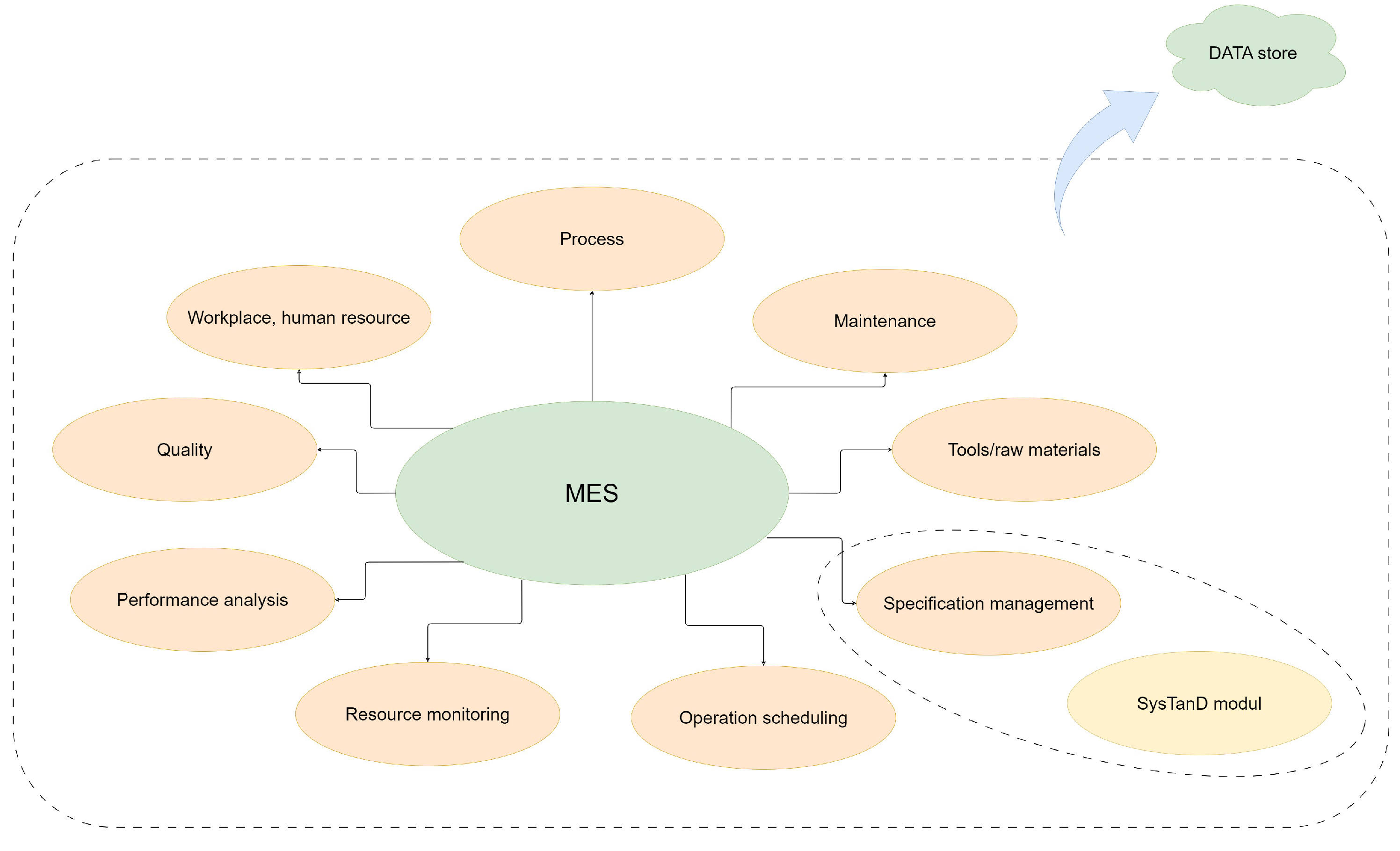
Enterprise framework (CIS—complex information system)MESResource management; workflow management; documentation; change management; cooperation with a standard module for autonomous recognition and application of relevant standard recommendations; example: digitized welding technical specification from customer ordering data (drawings).
Digital storage for welding knowledge and best practiceDocument handling subsystemRecommendation for quality-based technology areas; recommendation modul for the application of directives, standards and certifications; example: data lake technology with SOA with implemented web applications.
DataWelding parametersTechnological parameters for the production of workpiece; data storage, feedback, optimization; example: parameter optimization with ANN (Artificial Neural Network) predictor.
Transfer of data and communicationUse of modern data transmission tools, interfaces, cloud-based systems, human–machine interactions; example: intelligent interface technology and IO-link to transfer bus.
Technology proceduresAutomatizationApplication of automated technical equipment: robotic environment, microchip power sources; example: intelligent control units in robotcells.
Virtuality and simulationThe result of the welding process is an inherently destructible joint; by creating a simulation environment, the safety and quality of the process can be improved; example: CAW (Computer-Aided Welding), CAR-W (Computer-Aided Robotic Welding)—design manufacturing process and VR (Virtual Reality) technology
Sensor-based measurement systemRecognizing the correct position of the torch is essential for the good seams; the use of advanced image processing systems is necessary; example: sensor technology for welding torch position to recognize
CybersecuritySecurity levelsThe network of the CPS used is open to facilitate the fastest possible access, and the machines themselves use computer software systems that require the use of a common operating system; example: use of special hardware keys and intelligent software and access levels
Table 2. Zachman architecture and CIS’s components.
Aspects/PerspectivesWhatHowWhereWhoWhenWhyModel View
ContextualFact, business data/for analysis with cognitive resonanceBusiness Service with the synergy of the cognitive resonanceChain of Business Process WorkflowBusiness entity, functionChain of Business Process, WorkflowBusiness goalScope
ConceptualUnderlying Conceptual data model/Data Lake structured and unstructured dataService with added value originated by the cognitive resonanceService composition with cognitive business intelligenceActor, RoleBusiness Process ModelBusiness ObjectiveEnterprise Model
LogicalNotion hierarchy of CIS, Logical Model for structured, semi-structured and unstructured data of CISCognitive Service ComponentHierarchy of Components of CISActors, building blocks of ServiceBPEL, BPMN, OrchestrationBusiness RuleSystem Model
PhysicalObject hierarchy, Data modelCognitive Service ComponentHierarchy of Cognitive Service ComponentComponent, ObjectChoreographyRule DesignTechnical Model
DetailData in DBMSCognitive Service ComponentHierarchy of Cognitive Service ComponentComponent, ObjectChoreography, Security architectureRule specificationComponents
Functioning EnterpriseDataFunctionNetworkOrganizationScheduleStrategyService
Table 3. Detailed platform taxonomy.
Information system: PC + Nvidia Jetson TX2 model training and compression experiment
Platform Service CategorySubcategoryRequiredSupporting Technology
Data Interchange ServicesAudio ProcessingyesLibrosa (resampling, splitting, MFCC conversion)
Electronic Data InterchangeyesGoogle Drive
Data Management ServicesData Dictionary/RepositoryyesNumpy (encode dataset into binary format, .npy files)
Joblib (sklearn model persistence), PyTorch (pickle-based model serialization, .pt files), ONNX
Location and Directory ServicesFilteringyesImbalanced-learn (undersampling of majority class)
Network ServicesData Communicationsyeshttp, ftp
Distributed DatayesGoogle Drive
System and Network Management ServicesSoftware Installationyespip (Python package manager system)
Nvidia SDK Manager
Operating System ServicesCommand Interpreter and Utilityyespsutil (memory queries)
time
Software Engineering ServicesProgramming LanguageyesPython
Computer-Aided Software Engineering (CASE) Environment and ToolsyesGeany (IDE)
Software libraryyesPyTorch, Scikit-learn, TensorRT, Neural Network Distiller
Table 4. Criteria for evaluation of the design work by the design science research methodology: research activities [80].
Research Activities
Design Science Research
(Information Technology
/Information Systems/ Informatics)
Natural Science/
Behavior Science
Activities

/Artifacts
Build
(How It Was
Created,
Elaborated,
Used, Utilized,
Realized,
Implemented)
Evaluate
(The Component
Whether
Achieved
the Goals,
Fits the Purpose,
Worked Properly).
Theorize
(Generalize
Experiences,
Experiment,
Conclude
Discerned Facts)
Justify
(Underpin,
Buttress,
Support Your Ideas
 and
Experiment)
Research
Outputs
Constructs
Model
Method
Instantiation
Table 5. Evaluation criteria and list of questions from the viewpoint of the software case study research methodology [83].
Case Study Design
Case Study Design and Preparation for Data Collection1.What is the object of study?
2.Is a clear purpose/objective/research question/hypothesis/proposition defined upfront?
3.Is the theoretical basis—relation to existing literature and other cases—defined?
4.Are the authors’ intentions with the research made clear?
5.Is the case adequately defined (size, domain, process, etc.)?
6.Is a cause-effect relation under study? If yes, is the cause distinguished from other factors?
7.Will data be collected from multiple sources? Using multiple methods?
8.Is there a rationale behind the selection of roles, artefacts, viewpoints, etc.?
9.Are the case study settings relevant to validly address for the research question?
10.Is the integrity of individuals/organizations taken into account?
Preparation for Data Collection
11.Is a protocol for data collection and analysis derived (what, why, how)?
12.Are multiple data sources and collection methods planned?
13.For quantitative data, are the measurements well defined?
14.Are the planned methods and measurements sufficient to fulfil the objective of the study?
15.Is the study design approved by a review board and has informed consent obtained from individuals and organizations?
Case Study Design
Collecting Evidence and Analysis of Collected Data16.Are data collected according to the protocol?
17.Is the observed phenomenon correctly implemented (e.g., to what extent is a design method under study actually used)?
18.Are data recorded to enable further analysis?
19.Are sensitive results identified (for individuals, organization, or project)?
20.Are the data collection procedures well traceable?
21.Do the collected data provide the ability to address the research question?
Analysis of Collected Data
22.Is the analysis methodology defined, including roles and review procedures?
23.Is a chain of evidence shown with traceable inferences from data to research questions and existing theory?
24.Are alternative perspectives and explanations used in the analysis?
25.Is a cause-effect relation under study? If yes, is the cause distinguished from other factors?
Reporting Reporting
28.Are the case and its context adequately reported?
29.Are the research questions and corresponding answers reported?
30.Are related theory, hypotheses, and propositions clearly reported?
31.Are the data collection procedures presented, with relevant motivation?
32.Are sufficient raw data presented?
33.Are the analysis procedures clearly reported.
34.Are threats to validity analyses reported?
35.Are ethical issues reported openly (personal intentions, integrity issues)
36.Does the report contain conclusions, implications for practice and future research?
37.Does the report give a realistic and credible impression?
38.Is the report suitable for its audience, easy to read and well structured?
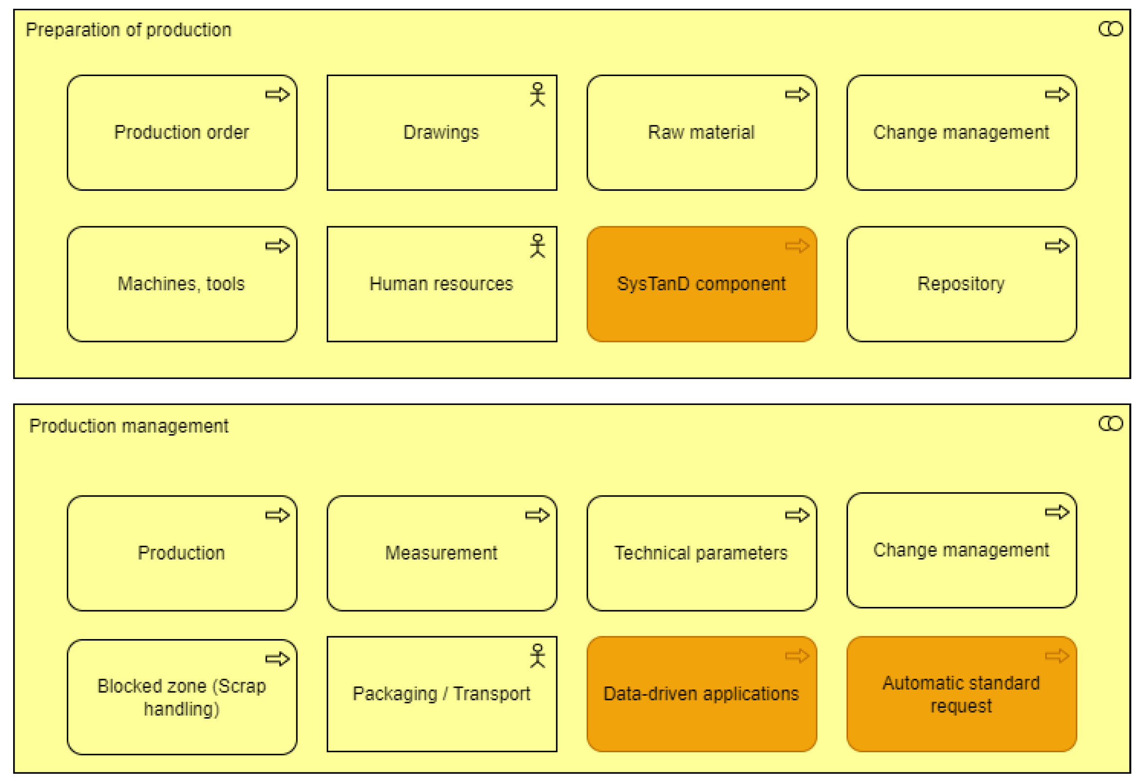
Table 6. Development roadmap for the future of working on SysTanD components.
No.Milestones of Main Activities/Details
1.MES components and business function definition
   1.1Definition of machine environment involving 1st CNC machine
   1.2Creating business workflows
      1.2.1Definition of services: DCU-DACQ modules, Rule-engine for intelligent integration capability
      1.2.2Definition of machine workstation master data: equipment workplace, machine state, downtime reasons, physical signals, number of items ordered,
   1.3Workflow management involving 2nd CNC machine and welding robot cell
   1.4B2B relationship definition in MES
   1.5Create a system connection between ERP-MES
2.Designation of pilot standards
   2.1Definition of workpieces and sample drawing for customer expectations
      2.1.1Technologization of the chosen workpiece (process, manufacturing environment, raw material, welding consumables, shielding gas, WPQR process test)
      2.1.2Selection of related standards and directives
   2.2Definition of standard object classes for pilot standards
3.SQL database development
   3.1Defining the database structure
      3.1.1Database implementation
      3.1.2SQL-MES software integration
   3.2Database upload—data migration
4.1st Testing Phase (pilot standards implementing)
   4.1Summary of software run experiences
   4.1.1Collection of functional gaps
   4.1.2Identification of improvement steps
5.2nd Testing Phase (main standards and directives—project extension)
   5.1Summary of software run experiences
   5.1.1Collection of functional gaps
   5.1.2Identification of improvement steps
Disclaimer/Publisher’s Note: The statements, opinions and data contained in all publications are solely those of the individual author(s) and contributor(s) and not of MDPI and/or the editor(s). MDPI and/or the editor(s) disclaim responsibility for any injury to people or property resulting from any ideas, methods, instructions or products referred to in the content.

