4D Remeshing Using a Space-Time Finite Element Method for Elastodynamics Problems
Abstract
:1. Introduction
2. Principle of the Method
- Choosing a Lagrange interpolation for displacements implies that displacements are continuous, but the velocities are discontinuous. As a consequence, integration by parts as in (3) is not totally rigorous, and it could be necessary to use the discontinuous Galerkin formulation, which amounts to writing the derivative of velocity within the theory of distributions. We will preserve the formulation in (3), knowing that the error here is of the same order as in the case of traditional finite elements in space. Indeed, with a Lagrange interpolation local displacements are continuous, whereas the global deformation is discontinuous.
- Even if it is not absolutely necessary, the advantage of using a laminated mesh such as defined here is that it becomes possible, rather than assembling the total matrix , to only assemble the sub-matrices . This considerably reduces the size of the systems to be solved. More precisely, the size of these linear systems is exactly the same as that obtained in the case of approaches based on the coupling of finite incremental differences in time with finite elements in space. Moreover, the method is not limited to simplex elements, and the spatial position of each set of nodes can vary from one time plane to the other. It is one of the main advantages of the method.
- We specify that the nodal vector relating the boundary conditions with velocity is written as:where is given starting from conditions of initial velocity while is unknown. Consequently, the resolution of System (16) is the following:The first system of equations,provides ; the system of equations:provides the displacements ; and the last system of equations,gives .
- Finally, the matrices of resolution are generally non-symmetric, even if the total matrix is symmetric. Thus, for the algorithm presented above, a non-symmetrical solver should be used. This can appear penalizing in terms of computing time. However, since the final objective is to use this approach to deal with problems of contact with friction and since the nonlinear resolution we developed in [14] is of the Gauss–Seidel nonlinear type, asymmetries do not affect computing time.
3. 4D Mesh and Remeshing
3.1. 4D Mesh Generation
3.2. Remeshing Technique
4. Numerical Analysis
4.1. Stability
- For 1D space-time elastodynamic applications, the use of the STFEM method with linear simplex elements is similar to the use of the implicit Newmark integration scheme with and . The method is then unconditionally stable.
- For 2D space-time elastodynamic applications, the use of the STFEM method with linear simplex elements is similar to the use of the explicit Newmark integration scheme with and . The method is then conditionally stable. Classically, the time step has to verify the CFLcondition: , where each is the frequency of a normal mode of vibration.
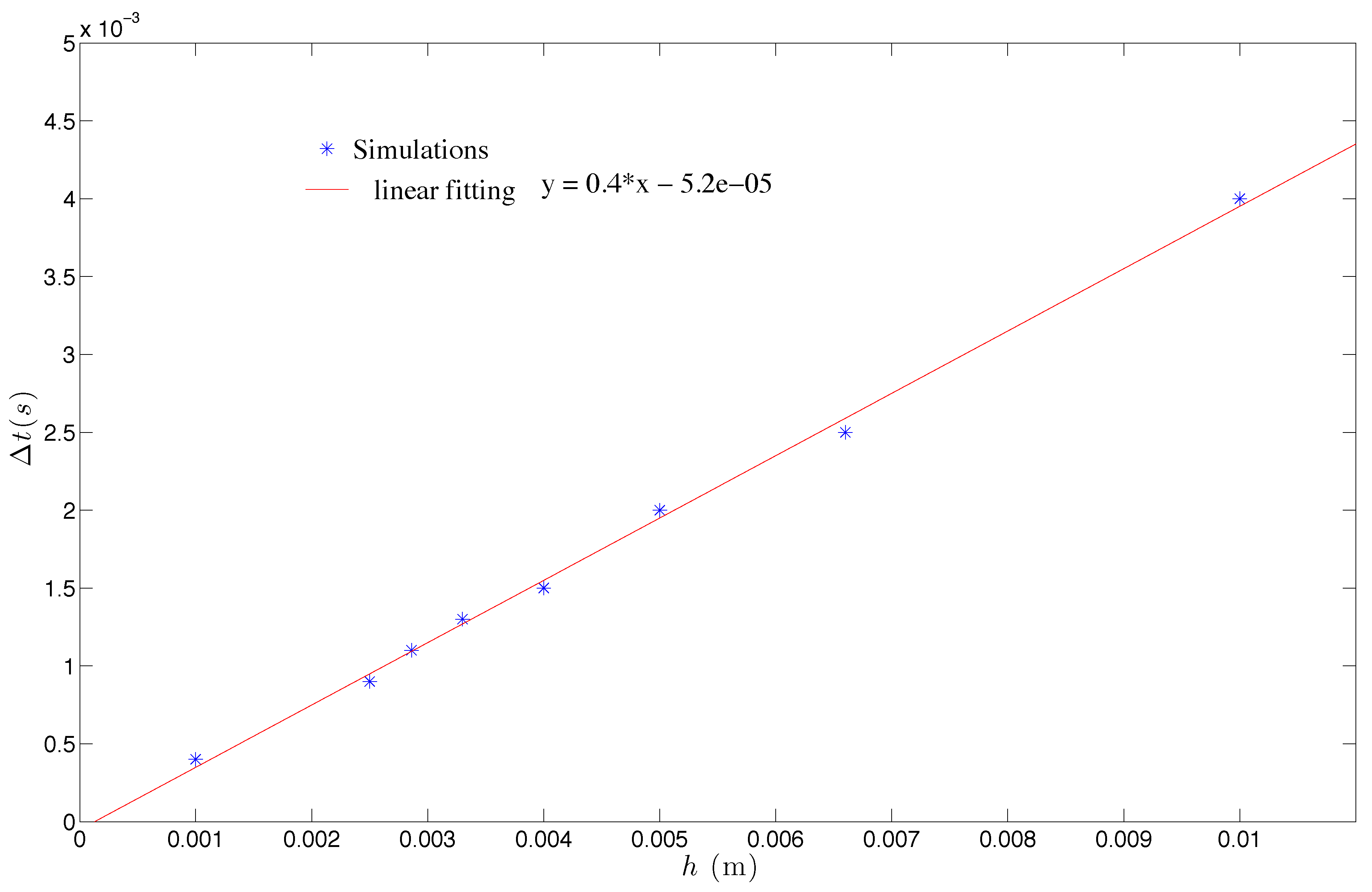
- For higher dimensions (3D and 4D), no direct relationship between the STFEM and the Newmark method has been established. Nevertheless, we noted that our method required sufficiently small space-time slabs, of the same order of the discretization time step necessary with explicit methods of integration.
- Furthermore, the use of the STFEM method with multiplex elements is similar to the use of the implicit Newmark integration scheme with and , for 1D, 2D, 3D and 4D space-time applications. In this case, the method is unconditionally stable.
4.2. Convergence
5. Numerical Results on Mesh Adaptation
6. Conclusions
Author Contributions
Conflicts of Interest
References
- Ladevèze, P. Non Linear Computational Structural Mechanics, New Approaches and Non Incremental Methods of Calculation; Springer: New York, NY, USA, 1999. [Google Scholar]
- Hughes, T.J.R.; Hulbert, G.M. Space-time finite element methods for elastodynamics: Formulations and error estimates. Comput. Methods Appl. Mech. Eng. 1988, 66, 339–363. [Google Scholar] [CrossRef]
- Hulbert, G.M.; Hughes, T.J.R. Space-time finite element methods for second-order hyperbolic equations. Comput. Methods Appl. Mech. Eng. 1990, 84, 327–348. [Google Scholar] [CrossRef]
- Khalmanova, D.K.; Costanzo, F. A space-time discontinuous Galerkin finite element method for fully coupled linear thermo-elasto-dynamic problems with strain and heat flux discontinuities. Comput. Methods Appl. Mech. Eng. 2008, 197, 1323–1342. [Google Scholar] [CrossRef]
- Argyris, J.H.; Scharpf, D.W. Finite elements in time and space. Nucl. Eng. Des. 1969, 10, 456–464. [Google Scholar] [CrossRef]
- Zienkiewics, O.C.; Parekh, C.J. Transient field problems-two and three dimensional analysis by isoparametric finite elements. Int. J. Numer. Methods Eng. 1970, 2, 61–71. [Google Scholar] [CrossRef]
- Chien, C.C.; Yang, C.S.; Tang, J.H. Three-dimensional transient elastodynamic analysis by a space and time-discontinuous Galerkin finite element method. Finite Elem. Anal. Des. 2003, 39, 561–580. [Google Scholar] [CrossRef]
- Anderson, M.; Kimn, J.-H. A numerical approach to space-time finite elements for the wave equation. J. Comput. Phys. 2007, 226, 466–476. [Google Scholar] [CrossRef]
- Idesman, A.V. Solution of linear elastodynamics problems with space-time finite elements on structured and unstructured meshes. Comput. Methods Appl. Mech. Eng. 2007, 196, 1787–1815. [Google Scholar] [CrossRef]
- Huang, H.; Costanzo, F. On the use of space-time finite elements in the solution of elasto-dynamic problems with strain discontinuities. Comput. Methods Appl. Mech. Eng. 2002, 191, 5315–5343. [Google Scholar] [CrossRef]
- Karaoglan, L.; Noor, A.K. Space-time finite element methods for sensitivity analysis of contact/impact response of axisymmetric composite structures. Comput. Methods Appl. Mech. Eng. 1997, 144, 371–389. [Google Scholar] [CrossRef]
- Jourdan, F.; Bussy, P. Large time increment method in dynamic regularization: Sheet cutting simulations. Comput. Methods Appl. Mech. Eng. 2000, 190, 1245–1259. [Google Scholar] [CrossRef]
- Li, X.D.; Wiberg, N.-E. Implementation and adaptivity of space-time finite element method for structural dynamics. Comput. Methods Appl. Mech. Eng. 1998, 156, 211–229. [Google Scholar] [CrossRef]
- Adélaïde, L.; Jourdan, F.; Bohatier, C. Frictional contact solver and mesh adaptation in Space-Time Finite Element Method. Eur. J. Mech. A/Solids 2003, 22, 633–647. [Google Scholar] [CrossRef]
- Donea, R.; Huerta, A.; Sarrate, J. Arbitrary Lagrangian-Eulerian for fluid-rigid body interaction. Comput. Methods Appl. Mech. Eng. 2001, 190, 3171–3188. [Google Scholar]
- Erickson, J.; Guoy, D.; Sullivan, J.M.; Üngör, A. Building spacetime meshes over arbitrary spatial domains. In Proceedings of the 11th International Meshing RoundTable, Sandia, Ithaca, NY, USA, 15–18 September 2002; pp. 391–402. [Google Scholar]
- Farhat, C.; Degand, C. A three-dimensional torsional spring analogy method for unstructured dynamic meshes. Comput. Struct. 2002, 80, 305–316. [Google Scholar]
- Feng, Y.T.; Peric, D. A time-adaptive space-time finite element method for incompressible Lagrangian flows with free surfaces: Computational issues. Comput. Methods Appl. Mech. Eng. 2000, 190, 499–518. [Google Scholar] [CrossRef]
- Mohr, R.; Menzel, A.; Steinmann, P. A consistent time FE-method for large strain elasto-plasto-dynamics. Comput. Methods Appl. Mech. Eng. 2008, 197, 3024–3044. [Google Scholar] [CrossRef]
- Tezduyar, T.E.; Sunil, S. Enhanced-discretization space-time technique (EDSTT). Comput. Methods Appl. Mech. Eng. 2004, 193, 1385–1401. [Google Scholar] [CrossRef]
- Tezduyar, T.E.; Sathe, S.; Keedy, R.; Stein, K. Space-time finite element techniques for computation of fluid-structure interactions. Comput. Methods Appl. Mech. Eng. 2006, 195, 2002–2027. [Google Scholar] [CrossRef]
- Adélaïde, L.; Jourdan, F.; Bohatier, C. Méthode des éléments finis espace-temps et remaillage. Rev. Eur. Elem. Finis 2003, 12, 427–459. [Google Scholar] [CrossRef]
- Idesman, A.; Niekamp, R.; Stein, E. Continuous and discontinuous Galerkin methods with finite elements in space and time for parallel computing of viscoelastic deformation. Comput. Methods Appl. Mech. Eng. 2000, 190, 1049–1063. [Google Scholar] [CrossRef]
- Adélaïde, L.; Jourdan, F.; Bohatier, C. New results on mesh adaptation in space-time finite element method. In Proceedings of the ASME Engineering Technology Conference on Energy (ETCE 2002/STRUC-29042), Houston, TX, USA, 4–5 February 2002. [Google Scholar]
- Miller, S.T.; Kraczek, B.; Haber, R.B.; Johnson, D.D. Multi-field spacetime discontinuous Galerkin methods for linearized elastodynamics. Comput. Methods Appl. Mech. Eng. 2009, 199, 34–47. [Google Scholar] [CrossRef]
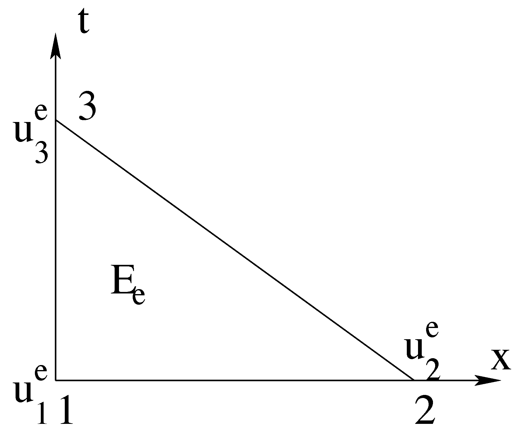
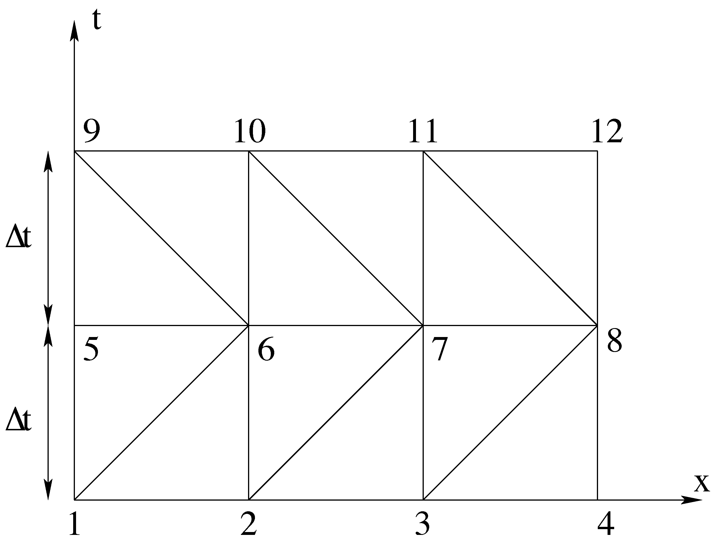
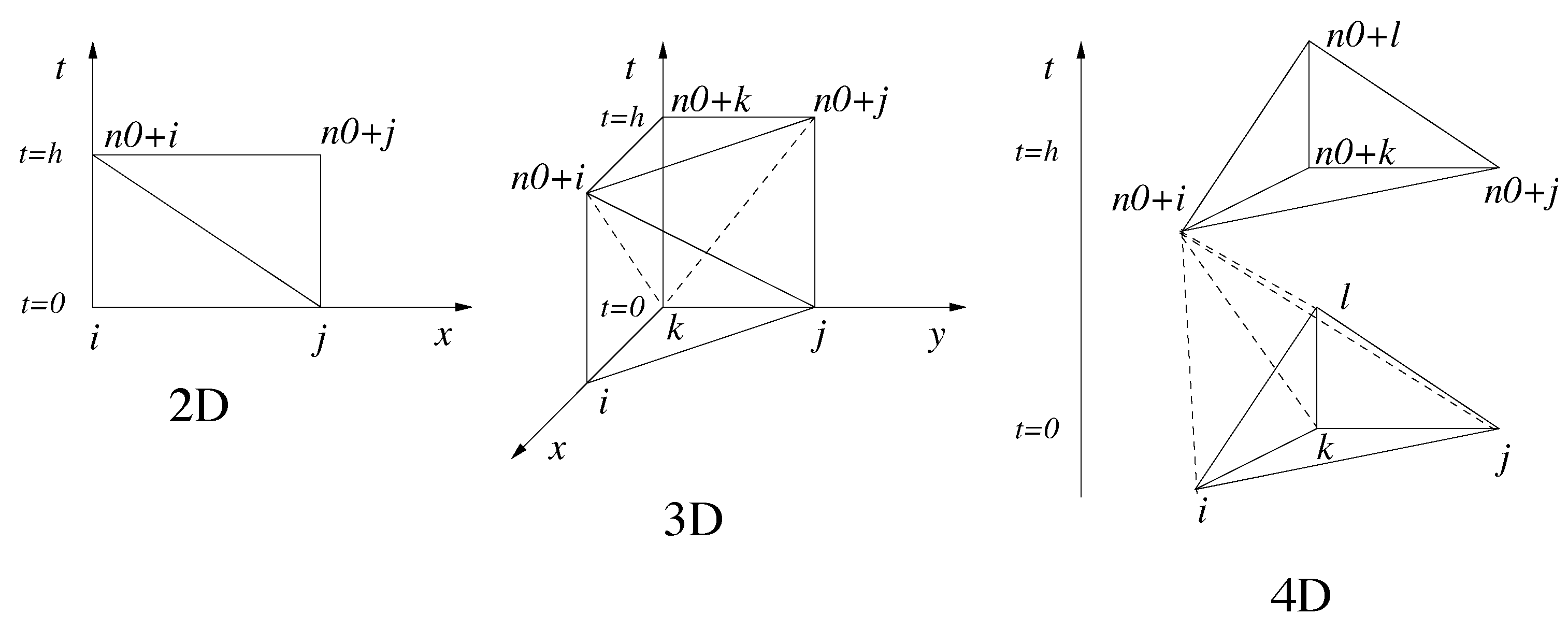
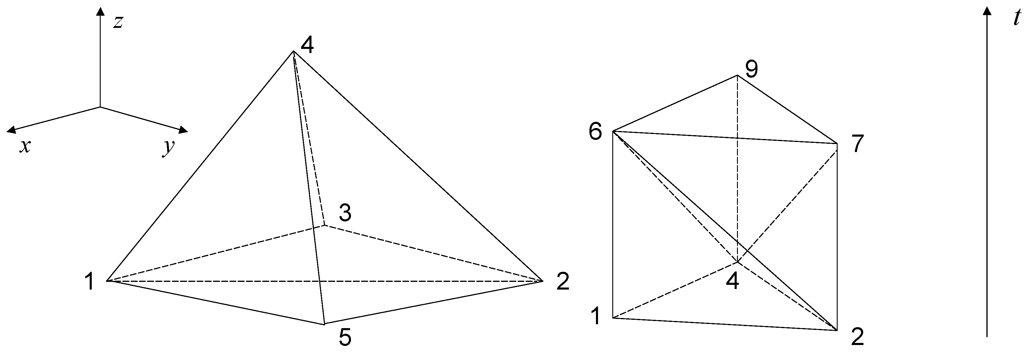



| Element Number | Node 1 | Node 2 | Node 3 | Node 4 | Node 5 |
|---|---|---|---|---|---|
| 1 | 1 | 2 | 3 | 4 | 6 |
| 2 | 2 | 3 | 4 | 6 | 7 |
| 3 | 3 | 4 | 6 | 7 | 8 |
| 4 | 4 | 6 | 7 | 8 | 9 |
| 5 | 1 | 2 | 4 | 5 | 6 |
| 6 | 2 | 4 | 5 | 6 | 7 |
| 7 | 4 | 5 | 6 | 7 | 9 |
| 8 | 5 | 6 | 7 | 9 | 10 |
© 2018 by the authors. Licensee MDPI, Basel, Switzerland. This article is an open access article distributed under the terms and conditions of the Creative Commons Attribution (CC BY) license (http://creativecommons.org/licenses/by/4.0/).
Share and Cite
Dumont, S.; Jourdan, F.; Madani, T. 4D Remeshing Using a Space-Time Finite Element Method for Elastodynamics Problems. Math. Comput. Appl. 2018, 23, 29. https://doi.org/10.3390/mca23020029
Dumont S, Jourdan F, Madani T. 4D Remeshing Using a Space-Time Finite Element Method for Elastodynamics Problems. Mathematical and Computational Applications. 2018; 23(2):29. https://doi.org/10.3390/mca23020029
Chicago/Turabian StyleDumont, Serge, Franck Jourdan, and Tarik Madani. 2018. "4D Remeshing Using a Space-Time Finite Element Method for Elastodynamics Problems" Mathematical and Computational Applications 23, no. 2: 29. https://doi.org/10.3390/mca23020029
APA StyleDumont, S., Jourdan, F., & Madani, T. (2018). 4D Remeshing Using a Space-Time Finite Element Method for Elastodynamics Problems. Mathematical and Computational Applications, 23(2), 29. https://doi.org/10.3390/mca23020029


