Abstract
Micro-scale fluids are tiny droplets that adhere to the surface of an object as a result of rainfall, perspiration, etc. Micro-scale fluid simulation is widely used in fields such as film and games. The existing state-of-the-art simulation methods are not suitable for simulating water droplets moving on a surface due to the fact that the water droplets cannot leave the texture space and their movements always depend on the continuous UV region. In this study, a novel method for simulating water droplets moving on a surface is proposed. We divide the droplets into two types: (1) two-dimensional droplets and (2) three-dimensional droplets and we implement the transformation between two-dimensional droplets in the texture space and three-dimensional droplets in the physical space. In the preprocessing phase, jump textures, coordinate transform textures and force field textures are generated in the non-continuous UV regions on a 3D object’s surface. In the process of simulation, water droplets are treated as rigid particles. The Velocity-Verlet-based method is adopted to solve the motion trajectory equation, and the boundary droplet transport algorithm is implemented based on jump texture. In the process of rendering, the height map is generated according to the simulation in the texture space and then the liquid bridge phenomenon between the droplets is simulated based on the Gaussian blur and the color rank algorithm. Finally, they are converted into normal texture-rendering droplets. The experimental result shows that the proposed method works well when simulating the movements of water droplets on a surface in a real-time manner, and it makes the movement simulation of dimension-reducing water droplets no longer depend on the continuous surface and continuous UV region. Moreover, the simulation efficiency of the proposed method is two times higher than that of the Smoothed Particle Hydrodynamics (SPH) method.
1. Introduction
Fluid simulation, as a key technology to enhance the sense of the reality of 3D objects, is a hot research topic in the field of physics. Micro-scale fluids are tiny droplets that adhere to the surface of an object as a result of rainfall, perspiration, etc. In large-scale fluid simulations (e.g., wave simulations, dam failure simulations), the volume of the fluid is usually similar to or larger than the object being interacted with. In micro-scale fluid simulations, the fluid is usually in the form of droplets, which are much smaller than the object they interact with. Questions such as how the droplets adsorb to the surface of the object and the loss of mass of the droplets themselves during the interaction are of concern.
Micro-scale fluid simulation is widely used in fields such as film and television, games, and transportation, e.g., by introducing micro-scale fluid simulation, raindrops can interact realistically with the surface of objects in 3D game scenes, which will greatly enhance the realism of 3D scenes. In addition, micro-scale fluid simulation can be used to generate street scenes with realistic windscreen raindrops. Existing methods for fluid simulation can be grouped into two categories: three-dimensional simulation methods and dimensional reduction simulation methods. The former simulates the movement of water droplets in a three-dimensional space, uses a 3D grid to render water droplets, and the simulation efficiency is low due to the expensive computing cost. The latter simulates the movement of water droplets in a two-dimensional space and uses normal mapping to render the water droplets. The simulation efficiency is excellent but the water droplets cannot leave the texture space and the water drop motion depends on the continuous UV region.
In order to address these issues, we propose a three-dimensional and two-dimensional combined method to simulate the movement of water droplets on a surface, which realizes the transformation of two types of water droplets based on coordinate space transformation. After transformation, the water droplets inherit the position, mass and speed of the original droplets. Three-dimensional water droplets are rendered by a three-dimensional grid, while two-dimensional water droplets in the texture space are rendered by a normal map. The main contribution of this paper can be summarized as:
- (1)
- The paper proposes a new method of downscaling micro-scale fluid simulation, which enables the droplet to be lossless transformed and continuously simulated in the 3D world space and 2D texture space, keeping the physical properties and motion of the droplet unchanged before and after the transformation, with realistic simulation effect and higher simulation efficiency than the existing downscaling simulation methods;
- (2)
- The paper proposes a jump texture, which enables the downscaled fluid simulation method to be carried out between discontinuous UV islands so that the user does not need to ensure the continuity of UV division, which is more convenient to use;
- (3)
- The paper proposes a 2D image processing algorithm-based liquid bridge simulation method between droplets, which is simple, efficient and easy to use, with intuitive parameters for user adjustment.
2. Related Work
There are three types of methods for fluid simulation: the eulerian method [1,2,3,4,5], the Lagrangian method [6,7,8,9,10] and the mixed method [11,12,13,14]. All of these methods are based on Navier–Stokes equations and work well in large-scale water simulations without regard to the water droplets’ adhesion force, surface tension and other factors. However, the low efficiency is the main shortcoming while applying these methods to micro-scale fluid simulation (e.g., the movement of water droplets on 3D object surfaces).
Aiming to address the above-mentioned issues, particle-based methods [15] and image-based screen post-processing methods [16] are proposed. However, these two types of methods suffer from the issue that the simulated raindrops cannot interact with objects in the scene in a real-time manner, hence a number of methods were proposed, e.g., Chen [17] et al. proposed a heuristic simulation method of water droplet movement based on lattice points on glass plates. However, this method can only apply to the water droplet movements on a plane. Zhang [18] et al. simulated the solid–liquid interaction of droplets based on the display surface method, which realized the interaction between the droplets and the surfaces of any shaped object. However, the procedure was very complex. Xu [19] et al. introduced surface tension and viscosity with the Smoothed Particle Hydrodynamics (SPH) model, which addressed the problem that the SPH model cannot be directly applied to the simulation of droplet movements. Yang [20] et al. proposed a new SPH fluid simulation formula to simulate the surface tension of micro-scale droplets, which successfully simulated the impact animation of droplets and the water surface. However, the method was complex and had low efficiency.
Lin [21] et al. simulated tear animation of virtual characters by developing an independent three-dimensional grid for the wake of teardrop movements. Alkawaz [22] et al. used the improved SPH method in a similar way as [19] to simulate a virtual human’s tears and perspiration. However, the above two methods still suffer from the problem of high computing costs. Xiao [23] et al. proposed an SPH-based dimensional reduction simulation method for tear animation, which transformed the physical simulation to a two-dimensional space using tangent space transformation and completely avoided the problem of point-plane collision in the three-dimensional space. However, these methods still suffer from two shortcomings: (1) These existing methods for downscaled micro-scale fluid simulation assume that the raindrops will not leave the texture space and once they do, they will be removed directly. This results in the inability of these methods to perform continuous fluid simulations between the 3D space and the texture space; (2) these existing methods do not take into account the effect that discontinuous UV regions (UV island, which is translated as UV Region in the text and can be replaced in bulk) have on the continuity of downscaled simulations, and therefore cannot be used to UV divide discontinuous model surfaces.
3. Method
In this study, we divided water droplets into two types: three-dimensional droplets and two-dimensional droplets, and water droplets can transform each other and inherit physical properties. When the three-dimensional water droplet collides with the object’s surface, it will be transformed into a two-dimensional water drop. When the critical condition is reached, the two-dimensional droplet is transformed into a three-dimensional one. The workflows of the transformation are shown in Figure 1a,b.
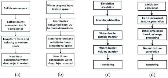
Figure 1.
Transformation Process: (a) 3D droplet transformed to 2D droplet; (b) 2D droplet transformed to 3D droplet; (c) the water droplet process in UV boundary; (d) water droplet Simulation Flow in 2D Texture Space.
These existing dimension-reduction methods record tangent space force, which is used for force field texture for physical simulation computation and generation of normal textures. However, if there exists non-continuous division UV area on the three-dimension surface when the water droplets move through the UV boundaries, the simulation method cannot work as expected. In order to solve this problem, a jump texture of a discontinuous UV region is introduced in the phase of pre-computation, which records the actual contiguous position of discontinuous UV edges. In the phase of physical simulation, when the two-dimensional water droplets in the tangent space move to these UV boundaries, the continuous water droplet motion simulation can be correctly executed through the method proposed in this paper. The workflow of the water droplets process in UV boundary is shown in Figure 1c.
For simulations of the phenomenon of integration, separation, and other details among water droplets, the simulation efficiency of surface display method [18] and SPH method [19,20,22,23] significantly decreases when water droplets increase. The proposed method treats the physics simulation of the droplet particles as a rigid body and then processes texture images to obtain detailed effects. The workflow of processing two-dimensional water droplets in texture space is shown in Figure 1d.
3.1. Preprocessing
In the preprocessing phase, we pre-compute the physical properties of the model surface and bake them into the map to speed up the runtime computation. The process of the physical properties obtained in the precomputed mapping and their baking process are described as follows.
As shown in Figure 2a, there are two different modes of three-dimensional surface UV expansion. All surface edges in Figure 2b are in the continuous texture space, while the flattened three-dimensional surface in Figure 2c is divided into discontinuous UV regions in texture space. In the UV expansion of complex models, the latter is a common UV expansion method that can avoid overlapping UV. However, this expansion method cannot work in the reduced-dimensional fluid simulation without non-continuous UV boundary jump.
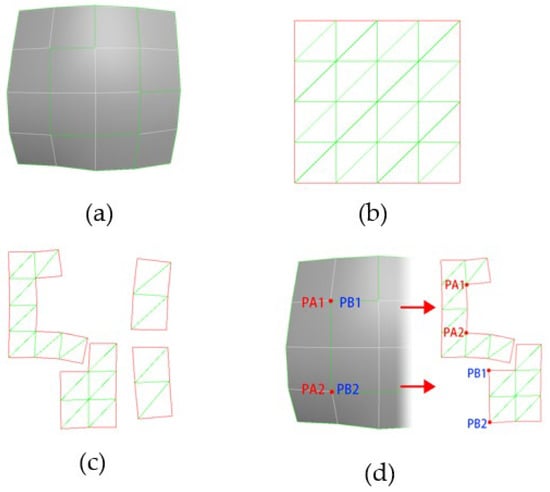
Figure 2.
UV expansions of different three-dimensional surfaces: (a) original 3D Surface; (b) continuous UV Expansion; (c) non-continuous UV Expansion; (d) correspondence of edges in model and in UV Region.
To solve such a problem, we calculate a non-continuous UV region jump texture, which records UV boundary relations on a map in RGB format. As shown in Figure 2d, when PA1 and PA2 (two endpoints of UV edge A) have the same local spatial coordinate PB1 and PB (two endpoints of UV edge B), A and B can be regarded as the same edge in the local space. At this point, all pixel coordinate positions on line segments PA1 and PA2 are recorded into the corresponding pixel values of line segments PB1 and PB2. Since all vertices’ coordinates in the texture space are two-dimensional coordinates in the range [0, 1], R and G channels of the jump texture are used to record the corresponding jump values. Meanwhile, B channel is used to record whether the corresponding local space coordinates of the pixel point are on the three-dimensional surface.
The coordinate transformation texture records the correspondence between the pixel position in the texture space and the local space position on the model surface on a map in RGBA format. Prior to calculating the corresponding local spatial coordinates of any point in the texture space, its triangle index should be retrieved. For any point Pin ΔABC, the area of ΔABC and three small areas of the triangle (ΔABP, ΔBPC and ΔCPA), which are divided by P point, can be calculated. The area of the triangles can be treated as the three vertices’ “contribution” for point P, therefore the corresponding local space coordinates of point P are calculated as:
The coordinates of point A are recorded into the texture map once they are calculated. The three-dimensional coordinate components in local space may be larger than [0, 1], therefore the coordinates need to be compressed to the range that the texture format can be described. Assuming that the absolute value of the maximum component of all vertices’ three-dimensional coordinates in the model’s local space is , the coordinate value recorded in the texture is:
Among them, R channel corresponds to the absolute value of its x component, G channel corresponds to the absolute value of its y component, and B channel corresponds to the absolute value of its z component. A channel is used to describe the negative values of coordinate components and the corresponding relations are shown in Table 1.

Table 1.
Negative mapping.
Finally, the force field texture records the information of external forces that will be received by a droplet at a particular pixel position within the texture space.
3.2. Droplet Type Conversion
We first convert the world space coordinates to texture space coordinates. The world coordinate of the model surface is obtained by the operations of rotation, translation and scaling of its local spatial coordinates. Therefore, for one point in the world coordinate, the corresponding local spatial coordinates can be obtained by inverse transformation. For any point (x, y, z)−1 in the world space, an extra dimension is added and the coordinates of it turn to homogeneous coordinates (x, y, z, 1)−1. Then, the transformation matrix of the model along the X, Y and Z coordinate axes is calculated as:
The transformation matrix after the model rotates θ Angle around the X-axis is calculated as:
The transformation matrix after the model rotates θ Angle around the Y-axis is calculated as:
The transformation matrix after the model rotates θ Angle around the Z-axis is calculated as:
Let , and be the rotation transformation matrix. Finally, for the zoom transformation matrix, the model scales kx, ky and kz times along the X, Y and Z axes, respectively, and the zoom transformation matrix is calculated as:
Therefore, for the point Pw = (x, y, z, 1)−1, where the water droplet collides with the surface in the world space, the collision point Pl in local space can be obtained:
The corresponding UV coordinate point Pu = (u, v) can be queried through Pl. In this way, the transformation from object surface coordinates in world space to corresponding texture space coordinates is completed. Then, we need to reduce the dimension of the physical simulation of water droplets to ensure we can solve it in texture space, an operation of Tangent space transformation is carried out to the external forces in world space. The force under local space is composed of α, β and γ—three components along three coordinate axes of local coordinate system. Therefore, the transformation matrix from local space to world space is:
Texture space is divided by triangular faces, which corresponds to the tangential T and B components of each triangular face surface of the model surface, therefore its normal vector can be obtained:
Therefore, the transformation matrix from texture space to local space is:
For the gravity G and wind Fw in world space, the above transformation matrix can be obtained to the external force Fe = G + Fw can be transformed into texture space:
Since the wind force does not affect the back of the model, its size is mapped to zero when calculating the wind force Fw with its direction parallel to the normal direction of a specific position on the model surface. In summary, the gravity and wind field in texture space is , and the pressure field is .
With the completion of the conversion on the water droplet coordinates, the speed and force of water droplet need to be converted too. In world space, three-dimensional water droplets are subjected to gravity, wind force, air resistance and air buoyancy, etc. With the transformation into texture space, two-dimensional water droplets are affected by gravity, wind force, pressure, friction between water droplets and the object surface, adsorption force and water droplet’s own surface tension. For initial velocity, when three-dimensional water droplets enter texture space, three velocity components can be obtained from transformation matrix.
Thus, the initial velocity of the two-dimensional water droplet obtained after conversion is:
For a two-dimensional water droplet entering the world space, its normal velocity component needs to be calculated during conversion, that is, the initial velocity of the three-dimensional water droplet after conversion is:
3.3. The Trajectory Equation of Water Droplets
The water droplet motion simulation is on a surface or a texture space. The physical computing process is as follows: for water droplets in a given size of two dimension texture space, given the initial position vector , initial velocity , their own quality , the adsorption on the surface of the object, surface tension , the static friction force , friction coefficient , the acceleration of gravity , gravity and wind field , with the time step defined as , try to solve the locus equation of water droplets on the two-dimensional facade. Among them, is determined by the collision point between the three-dimensional water drop and the object; denotes the tangential component of the water drop instant velocity on the object’s surface.
Figure 3 illustrates a water droplet on surface of an object. denotes the force along normal direction in the tangent space of object surface, namely the pressure on the water droplet; denotes the friction force; and are the two components of gravity and wind in the tangential direction of the tangent space.
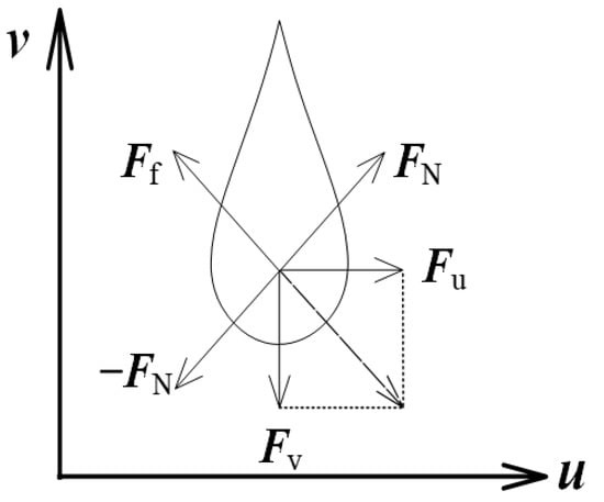
Figure 3.
The pressure distribution on the water droplet.
In , the pressure direction, the water droplet is affected by the adsorption force between surface and itself, its own surface tension and pressure field are calculated as:
denotes the surface tension between the water drop and the surface due to the bending trend, where k is the surface tension coefficient of the liquid, which is related to the type of liquid; represents the curvature of contact surface. Thus, the sliding friction force of the water drop is obtained:
If the speed of the water drop is , the direction of is and the combined force of the water drop in the texture space is . Therefore, the combined force of the water drop in the y and z planes at the moment is calculated as:
According to Equation (7), the tangential acceleration of the water droplet is:
When the droplet particles reach the critical state, the droplet will leave the texture space and enters the three-dimensional space. The critical state includes two cases: (1) when the droplet particles move in the texture space, they go beyond the boundary of unbounded UV; (2) the pressure on the droplet particles is negative.
Finally, velocity-Verlet integral is used to calculate the trajectory equation of water droplets. The velocity expression is:
The position can be described as:
Equations (18) and (19) were substituted into Equations (20) and (21), and then the expression of water drop velocity and position at the moment are obtained, respectively:
The position of water droplet at any time can be obtained through the position of water droplet at the previous time, while the speed and position of water droplets at zero time are known. Therefore, Equation (23) is the trajectory equation of water droplet particles.
3.4. Boundary Water Droplet Transmission
We transform the position of the water droplet. As shown in Figure 4, in each step of physical simulation, a new water droplet movement position is pre-computed. When water droplets move out from a UV region, it should be checked whether droplets’ motion path surpasses the boundary. We set the droplet to move from point A to point B, and passed point P on UV boundary, which was a point on path AB, and queried the corresponding jump information P′ in the jump texture. If P′ exists, the water droplets should be moved to the location.
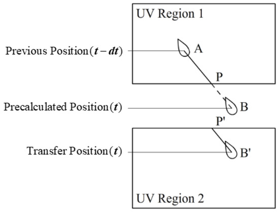
Figure 4.
Water droplet location transmission.
If P′ does not exist, the droplet reached the critical condition and transformed into a three-dimensional droplet.
As shown in Figure 5a, when the droplet location is directly transferred and the droplet particles have not completely left the UV region, part of the droplet volume outside the UV region will not be correctly rendered to the 3D surface, therefore it is necessary to transfer the droplet volume separately.
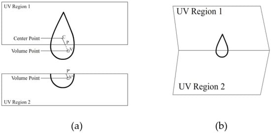
Figure 5.
Restoration of Droplet Volume Transfer: (a) non-continuous UV Region; (b) original 3D Surface.
As shown in Figure 5a, for the droplet’s volume point V, which is outside the UV region, point P, the intersection of VC, which is the linkage between V and the droplet central point C should be calculated. Then, the corresponding jump information P′ in the jump texture will be queried. If P′ exists, the position of the pixel is drawn as:
If P′ does not exist, the point will not be drawn (as shown in Figure 5b).
3.5. Separation and Coalescence of Water Droplets
In [17], when the speed of sliding water droplet exceeds a certain value and moves to the next position, a small water drop will be generated at the original position to form the wake of water drop movement. The mass of sliding water drops reduces the mass of the small water droplet. However, it is usually impossible to form a continuous stream or obtain trail detail only relying on the small water droplets after the separation of the bigger water droplet. Therefore, we increase wake interpolation subdivision by inserting small water droplets according to the subdivision value n between the original position and the new location of the dynamic water droplet through the dichotomy. As shown in Figure 6a, a higher segmentation value can make the trail look more like a continuous flow.
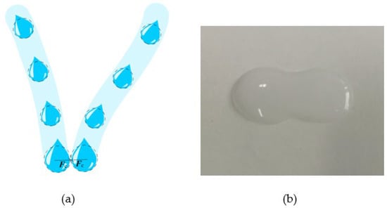
Figure 6.
Separation and coalescence of water droplets: (a) attraction between Droplets; (b) photo of real Liquid Bridge between water droplets.
In [17], the merging phenomenon between droplets is realized by making the droplets move first to lattice points with higher wetting degree. In [24], a spherical collider is established for each three-dimensional droplet. By increasing the attraction between the collision drops when collision occurs, the water drops move closer to each other and merge. Since physical simulation in this paper is mapped to two-dimensional space, collision detection is also carried out in two-dimensional space. As shown in Figure 6b, each droplet contains a two-dimensional circular collider, which is used to quickly detect the collision between droplets. When two water droplets collide, both of the two water droplets will become close to each other due to mutual attraction. When the distance between two water droplets’ centers is less than a certain value, they will merge into one water droplet and continue the movement of the force [25,26,27].
3.6. Liquid Bridge Simulation
As shown in Figure 6b, when one drop touches another, a phenomenon of siphoning will occur between these two drops to produce a liquid bridge [28,29,30,31]. In [18], the complex curved surface operation is used to simulate the liquid bridge. In [19], the direct physical method is used to simulate. As the number of water droplets increases, these methods suffer more computing costs. Therefore, in this study, Gaussian blur and color scale are adopted to process the whole texture, which contains all current water drops to obtain the final results quickly. The process consists of: (a): conducting Gaussian blur [32] on the Alpha channel of the whole texture; (b) conducting color order on the Alpha channel; and (c) mixing the processed Alpha channel and RGB color channel. Figure 7a is the Alpha channel of the original texture; Figure 7b is the result with a fuzzy radius of 4 pixels by Gaussian blur; Figure 7c shows the processed result of color order. The color order parameters include: (1) brightness: 11; (2) gray: 2.35 and (3) dark: 255.
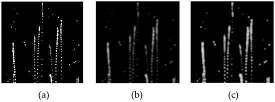
Figure 7.
Quick-Liquid Bridge Simulation of water droplets: (a) alpha channel of the original texture; (b) Gaussian blur processing results; (c) color order processing results.
3.7. Water Droplets Rendering
For two-dimensional water droplets, the normal texture is generated based on the calculated data of water droplets in texture space. In this paper, first the height map is generated, and then it will be transformed into normal texture. The radius and normal height of the droplet are determined by the mass of the droplet. Let the maximum droplet radius be Rm and the mass be mm, and then the radius of any droplet is calculated as:
If the central coordinate of a water drop is C, when drawing height map, the gray value of a point V on the water drop is calculated as:
Hg denotes the gray value of the central point of the droplet:
We substitute Equations (26) and (28) into Equation (27) and obtain:
The height map is then converted into a normal texture and the RGBA value for any pixel in the texture space is: (, , 1, 1). Among them:
lg, rg, ug, dg are the gray values of the pixels up and down around this pixel point respectively. The reflection and refraction effects of water droplets are rendered by capturing the screen background screenshots; warping and deflecting their UV based on normal maps.
4. Experiment
4.1. Experimental Settings
The experiment was carried out based on the Unity 3D engine. The system ran on a computer equipped with an Intel Core i7-7700hq CPU @2.80ghz eight-core CPU and NVIDIA GTX 1050 graphics card. The Unity 3D version was 5.3.4f1 (64-bit). The resolution of two dimension water droplets is 512 × 512 pixels.
4.2. Experimental Procedures
The experimental system consists of two parts. The first part is designed for the physical simulation and rendering of three-dimensional water droplets, and the second part is designed for the physical simulation and rendering of two-dimensional water droplets. The general process of the first part is shown in Figure 8a. In the pretreatment stage, three-dimensional water droplets of different masses are produced. The three-dimensional grid of water droplets used in the experiment is a square surface. The three-dimensional water droplets fall to the surface of the object through physical simulation and are converted into a two-dimensional water droplet in the texture space at the collision point.
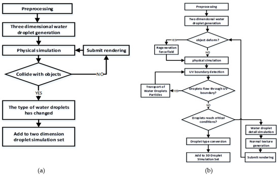
Figure 8.
The processing workflow: (a) the processing workflow for step 1; (b) the processing workflow for step 2.
The full workflow of the second part is shown in Figure 8b. The mass size and speed of the three-dimensional droplets are inherited by the two-dimensional drops and the data conversion is completed in the preprocessing stage. Then, the droplets continue to carry out a physical simulation in the texture space. The droplets leave the texture space on the surface of the object after reaching the critical condition and are converted into three-dimensional droplets again.
4.3. Experimental Result
Figure 9 and Figure 10 show the pre-computed texture results of the three-dimensional facets and the rabbit model surface with discontinuous UV expansion, in which the field texture contains the gravity field.

Figure 9.
Pre-Computed textures of a simple 3D facet.

Figure 10.
Pre-Computed textures of the Stanford Rabbit.
Figure 11 shows the calculation results of the droplet texture on the surface of three-dimensional surface slices and the rabbit model. The entire droplets move in the UV region and the two-dimensional droplets in the tangent space obtain the correct rendering results on the surface of the model.
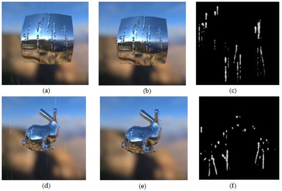
Figure 11.
Water Droplets Movement: (a) rendering Result (on the 3D Facet Surface); (b) wireframe Rendering Result (on the 3D Facet Surface); (c) water droplet Texture (on the 3D Facet Surface); (d) rendering Result (on the Surface of Rabbit Model); (e) wireframe Rendering Result (on the Surface of Rabbit Model); (f) water droplet Texture (on the Surface of Rabbit Model).
Figure 12 shows the simulation results of a water droplet’s movement on a discontinuous surface. In the scene, only gravity is concerned. During the dropping process, the water droplet passed through two discontinuous 3D surfaces and underwent four transformations. After sliding across the first surface, the droplet lost its mass due to leaving behind its wake. Its volume became smaller when it was converted from surface one to a three-dimensional drop and its volume reached its minimum when it was finally converted from surface two to another three-dimensional drop. Figure 13 shows the texture image simulation results of the two surfaces where the wake left by the movement of water droplets on the two surfaces can be seen.

Figure 12.
Drop from Discontinuous Surface: (a) a 3D Water droplet Dropping; (b) colliding with Surface; (c) transforming to a 2D water droplet and dropping; (d) transforming to a 3D Water Droplet and Leaving Surface; (e) continuing to drop; (f) colliding with Surface 2; (g) transforming to a 2D water droplet and dropping; (h) transforming to a 3D water droplet and dropping.
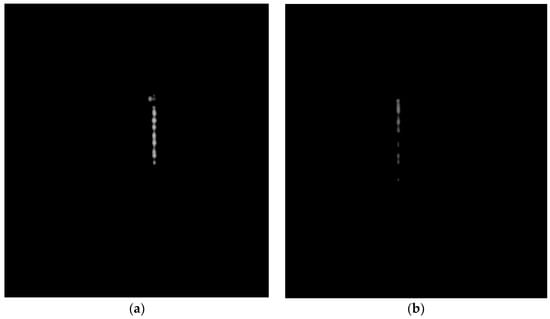
Figure 13.
Texture Mapping Simulation Results of the Two Surfaces. (a) Texture of the First Surface; (b) Texture of the Second Surface.
4.4. Analysis and Discussion
Figure 14 shows the comparison between the simulation results achieved by this method and the real photos.
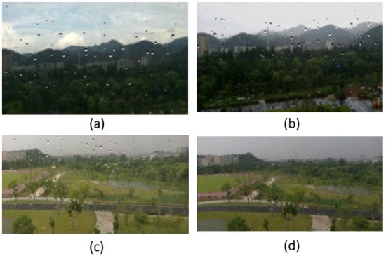
Figure 14.
Raindrop Motion Simulation in Different Circumstances: (a) raindrop Real Photo A; (b) simulation Result A; (c) raindrop Real Photo B; (d) simulation Result B.
As shown in Figure 15, there is a comparison of water droplet motion simulations on a sphere surface using different methods. The ordinary three-dimensional SPH method will cause error simulation results because, without viscosity and surface tension items, water droplet particles cannot slide down along the curved surface when the water droplet particles collide with the sphere surface. After introducing the viscosity and surface tension to the improved SPH method, the correct three-dimensional simulation results can be obtained. In the dimension reduction SPH simulation method, the water drop is drawn on the normal texture and rendered in texture mode. The water drop can slip along the surface but cannot leave the texture space. In the simulation results of the proposed method, the droplet particles are divided into two types. The droplet particles outside the texture space are rendered with a three-dimensional grid, while the droplet particles within the texture space of the object surface are rendered with a normal map. The correct trajectory of the water droplets can be generated and the water droplets can also leave the texture space.
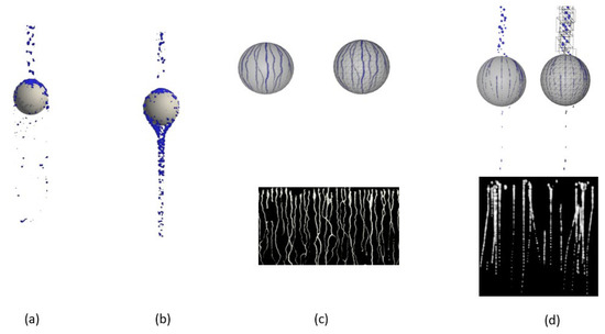
Figure 15.
Simulation Results of Spherical Surface: (a) 3D SPH Method Simulation Result; (b) improved 3D SPH Method Simulation Result; (c) dimension Reduction SPH Method Simulation Result; (d) simulation Result produced by Proposed Method.
Figure 16 shows the simulation results of dimensional reduction SPH and the proposed method applied for the division of the three-dimensional surface of the non-continuous UV region division. The white wireframe in the simulation texture is the range of the UV region. Because the dimension reduction SPH did not process the discontinuous UV region, a large number of droplet particles move out of the UV region in the simulation process, which causes a negative simulation result.

Figure 16.
Simulation result of discontinuous UV surfaces: (a) dimensional reduction SPH simulation result; (b) simulation texture result; (c) proposed method simulation texture; (d) simulation texture result based on the proposed method.
As shown in Figure 17, Figure 18 and Figure 19, in the comparison of the simulation result of different methods for virtual flow tears in different wind conditions, the proposed method achieved almost the same performance as that of the improved 3D SPH with the introduction of viscous and surface tension terms [19] and the reduced dimensional SPH method [23].
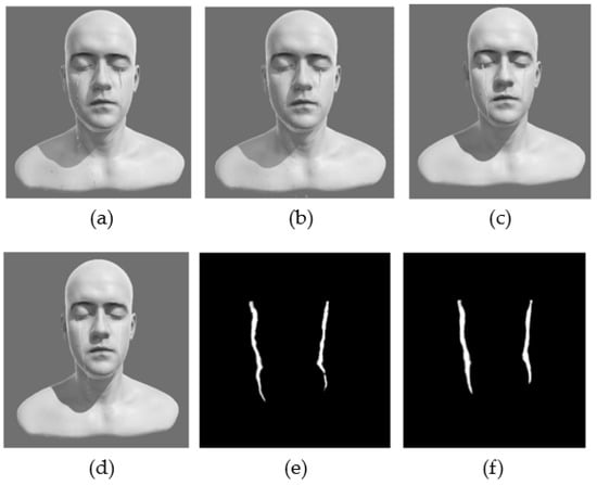
Figure 17.
The comparison of simulation results in the wind condition (0. 0, 0. 0, 0. 0): (a) result of plain 3D SPH simulation; (b) result of improved 3D SPH simulation; (c) result of reduced dimensional SPH simulation; (d) simulation result of the proposed method; (e) mapping result of the downscaled SPH simulation; (f) mapping result of the proposed method.
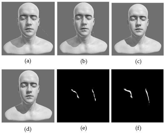
Figure 18.
The comparison of simulation results in the wind condition (10. 0, 0. 0, 0.0): (a) plain 3D SPH simulation result; (b) improved 3D SPH simulation result; (c) reduced SPH simulation result; (d) simulation result of the proposed method; (e) mapping result of the downscaled SPH simulation; (f) mapping result of the proposed method.
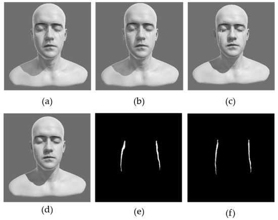
Figure 19.
The comparison of simulation results in the wind condition (0. 0, 0. 0, 5.0): (a) plain 3D SPH simulation result; (b) improved 3D SPH simulation result; (c) reduced SPH simulation result; (d) simulation result of the proposed method; (e) mapping result of the downscaled SPH simulation; (f) mapping result of the proposed method.
As shown in Figure 20, the simulation of the liquid bridge phenomenon by the fusion of water droplets with different methods was carried out. In the explicit surface-based simulation method, the two drops are simply superimposed, whereas the method proposed in this paper enables the drops to produce a good liquid bridge effect during the fusion process.
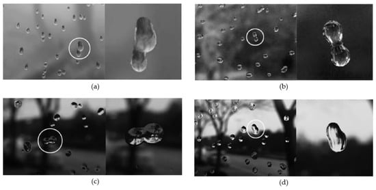
Figure 20.
The comparison of simulation results for wind speed (0.0, 0.0, 5.0): (a) simulation results based on deformable surface model; (b) simulation results based on improved 3D SPH; (c) simulation results based on reduced dimensional SPH; (d) simulation results based on the proposed method.
Table 2 shows the efficiency of the proposed method compared to the 3D SPH and reduced dimensional SPH for different particle numbers, with more than 10,000 triangular slices used in the experiments. Table 3 and Figure 21 show the comparison of the efficiency of the different methods for different numbers of triangular slices on the surface, the maximum number of particles used in the experiments is 5000. The experimental result shows that the simulation efficiency of the proposed method is two times and five times higher than that of the SPH-based 2D and 3D simulation methods, respectively.

Table 2.
Average frame rate of each method with different particle numbers (unit: frame/s).

Table 3.
Average frame rates of each method on the surface of different models (unit: frame/s).
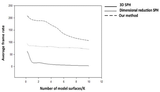
Figure 21.
Average frame rates of each method on the surface of different models.
The experimental result indicates that the proposed method is more efficient than other existing methods. In terms of rendering effect, the water droplets are simply superimposed in the display surface-based simulation method, while the SPH-based method and the proposed method achieve a good liquid bridge effect between water droplets. None of these downscaled raindrop simulation methods could achieve continuous raindrop trails on the surface using the discontinuous UV model, and the trails usually break at the UV cut edge. The plain 3D SPH method does not include the viscosity and surface tension terms in the simulation and the water droplet particles cannot slide down the surface after colliding with the sphere, resulting in incorrect simulation results. With downscaled simulation methods, water droplets are usually drawn on a normal texture and rendered as a texture, and the droplets can slide down the surface but cannot leave the texture space. The proposed method takes the effects of viscosity and surface tension terms into consideration and is able to simulate continuous fluid motion in both the 2D and 3D space. Meanwhile, it ensures that the motion of the droplet is consistent whether the transformation is introduced or not.
In addition, the proposed method achieves good flexibility, e.g., by inserting new drops based on the dichotomy in the two drops on the same trails generated in the two frames before and after, it is possible to simulate the water trails under different rain magnitudes. These existing methods often make it difficult to distinguish whether two drops belong to the same tail or not, and a large number of parameters need to be adjusted to generate water trails with different rainfall levels.
5. Conclusions
In this paper, a novel method for the real-time simulation of water droplet movement on a surface was proposed. Moreover, a comparison of simulation performance between the proposed method and the existing methods was carried out. The proposed method-based real-time simulation was easily obtained and three-dimensional and two-dimensional droplets could be transformed into each other. The proposed method solved the problem that water drops cannot leave the texture space in the existing dimensional reduction simulation methods.
The proposed method achieved a more than two-fold increase in computing efficiency while achieving almost the same result as the SPH method. Compared with other reduced-dimensional simulation methods, the proposed method performed continuous fluid simulation on the surface of a model with discontinuous UV division, which was of wider adoption and enabled 3D and 2D droplets to be converted to each other in any case, addressing the problem that droplets could not leave the texture space in downscaled simulation methods. Furthermore, we simulated liquid bridges between droplets with significantly higher simulation efficiency while achieving similar simulation quality compared to the existing methods.
However, the physical simulation of three-dimensional water droplets in the air was not detailed in this paper, and the simulation was not accelerated using GPU, which could be improved in the future.
Author Contributions
Conceptualization, Z.L. and Z.H.; methodology Z.H.; writing—original draft preparation, Z.H.; writing—review and editing, S.L., L.G. and J.C.; visualization, Z.H.; supervision, J.C.; project administration, L.G.;. All authors have read and agreed to the published version of the manuscript.
Funding
This study is supported by the Natural Science Foundation of Zhejiang Province (No. LY21F020005).
Data Availability Statement
The data is available by contacting the corresponding author.
Conflicts of Interest
The authors declare no conflict of interest.
References
- Pathak, A.; Raessi, M. A 3D, fully Eulerian, VOF-based solver to study the interaction between two fluids and moving rigid bodies using the fictitious domain method. J. Comput. Phys. 2016, 311, 87–113. [Google Scholar] [CrossRef]
- Qinghong, Z.; Shuyan, W.; Huilin, L.; Guodong, L.; Shuai, W.; Guangbo, Z. A coupled Eulerian fluid phase-Eulerian solids phase-Lagrangian discrete particles hybrid model applied to gas-solids bubbling fluidized beds. Powder Technol. 2017, 315, 385–397. [Google Scholar] [CrossRef]
- Tompson, J.; Schlachter, K.; Sprechmann, P.; Perlin, K. Accelerating Eulerian Fluid Simulation With Convolutional Networks. arXiv 2016, arXiv:1607.03597. [Google Scholar]
- Liu, Y.; Dinh, N.; Smith, R. A Validation and Uncertainty Quantification Framework for Eulerian-Eulerian Two-Fluid Model based Multiphase-CFD Solver. Part I: Methodology. arXiv 2018, arXiv:1806.03373. [Google Scholar]
- Adnan, M.; Sun, J.; Ahmad, N.; Wei, J.J. Validation and sensitivity analysis of an Eulerian-Eulerian two-fluid model (TFM) for 3D simulations of a tapered fluidized bed. Powder Technol. 2022, 396, 490–518. [Google Scholar] [CrossRef]
- Samulyak, R.; Wang, X.; Chen, H.-C. Lagrangian particle method for compressible fluid dynamics. J. Comput. Phys. 2018, 362, 1–19. [Google Scholar] [CrossRef]
- Kehl, C.; van Sebille, E.; Gibson, A. Speeding up Python-based Lagrangian Fluid-Flow Particle Simulations via Dynamic Collection Data Structures. arXiv 2021, arXiv:2105.00057. [Google Scholar]
- Grossi, E.; Shabana, A.A. Verification of a Total Lagrangian ANCF Solution Procedure for Fluid–Structure Interaction Problems. J. Verif. Valid. Uncertain. Quantif. 2017, 2, 041001. [Google Scholar] [CrossRef]
- Li, Z.; Farimani, A.B. Graph Neural Network for Lagrangian Fluid Simulation. APS Division of Fluid Dynamics Meeting Abstract. 2020. Available online: https://ui.adsabs.harvard.edu/abs/2020APS..DFDR09002L/abstract (accessed on 10 November 2022). [CrossRef]
- Nadkarni-Ghosh, S.; Bhattacharjee, J. Stability Analysis of Fluid Flows Using Lagrangian Perturbation Theory (LPT): Application to the Plane Couette Flow. Front. Phys. 2018, 6, 37. [Google Scholar] [CrossRef]
- Pfaff, T.; Thuereyb, N.; Gross, M.H. Lagrangian vortex sheets for animating fluids. ACM Trans. Graph. 2012, 31, 1–8. [Google Scholar] [CrossRef]
- Zhu, B.; Yang, X.; Fan, Y. Creating and Preserving Vortical Details in SPH Fluid. Comput. Graph. Forum 2010, 29, 2207–2214. [Google Scholar] [CrossRef]
- Wilczek, M.; Lalescu, C. A novel bridging relation connecting Eulerian and Lagrangian statistics. In Proceedings of the 70th Annual Meeting of the APS Division of Fluid Dynamics, Denver, CO, USA, 19–21 November 2017. [Google Scholar]
- Zwick, D.; Hackl, J.; Balachandar, S. Scalable Methods for Eulerian-Lagrangian Simulation Applied to Compressible Multiphase Flows. APS Division of Fluid Dynamics Meeting Abstract. 2017. Available online: https://ui.adsabs.harvard.edu/abs/2017APS..DFD.L2012Z/abstract (accessed on 10 November 2022).
- Weber, Y.; Jolivet, V.; Gilet, G.; Ghazanfarpour, D. A multiscale model for rain rendering in real-time. Comput. Graph. 2015, 50, 61–70. [Google Scholar] [CrossRef]
- Ding, W.; Zhu, Z.; Chen, X.; Zhang, C.; Liang, Y.; Li, S.; Fan, H.; Feng, H. Real-time rain and snow rendering. In Proceedings of the 2013 Second International Conference on Agro-Geoinformatics (Agro-Geoinformatics), Fairfax, VA, USA, 12–16 August 2013. [Google Scholar]
- Chen, K.C.; Chen, P.S.; Wong, S.-K. A heuristic approach to the simulation of water drops and flows on glass panes. Comput. Graph. 2013, 37, 963–973. [Google Scholar] [CrossRef]
- Zhang, Y.; Wang, H.; Wang, S.; Tong, Y.; Zhou, K. A deformable surface model for real-time water drop animation. IEEE Trans. Vis. Comput. Graph. 2012, 18, 1281–1289. [Google Scholar] [CrossRef]
- Xu, S.; Zhang, X.; Chen, Y.; Yu, H.; Wu, E. Interactive simulation for water drop effects. J. Comput.-Aided Des. Comput. Graph. 2013, 25, 1159–1168. [Google Scholar]
- Yang, M.; Li, X.; Liu, Y.; Yang, G.; Wu, E. A novel surface tension formulation for SPH fluid simulation. Vis. Comput. 2017, 33, 597–606. [Google Scholar] [CrossRef]
- Lin, A.J.; Cheng, F. Modelling Three Dimensional Animated, Detailed, and Emotional Facial Expressions. Int. J. Model. Simul. 2013, 33, 47–53. [Google Scholar] [CrossRef]
- Alkawaz, M.H.; Basori, A.H.; Mohamad, D.; Mohamed, F. Realistic Facial Expression of Virtual Human Based on Color, Sweat, and Tears Effects. Sci. World J. 2014, 2014, 367013. [Google Scholar] [CrossRef]
- Xiao, M.; Liu, Z.; Shi, J.; Jin, W.; Liu, T.; Liu, C.; Liu, B. Simulation method of agents’ tears flowing. J. Comput. Aided Des. Graph. 2015, 27, 1669–1674. [Google Scholar]
- Djado, K.; Egli, R.; Granger, F. Particle-based drop animation on meshes in real time. Comput. Animat. Virtual Worlds 2012, 23, 301–309. [Google Scholar] [CrossRef]
- Adrien, B.; Nate, C.; Manu, P. Dancing droplets: Contact angle, drag, and confinement. APS Division of Fluid Dynamics (Fall), Boston, MA, USA; 2015; A32.009; Available online: https://absimage.aps.org/image/DFD15/MWS_DFD15-2015-002394.pdf (accessed on 10 November 2022).
- Gehrke, S.; Wirth, K.-E. Interaction phenomena between liquid droplets and hot particles—Captured via high-speed camera. Particuology 2009, 7, 260–263. [Google Scholar] [CrossRef]
- Hao, P.; Lv, C.; He, F. Evaporating behaviors of water droplet on superhydrophobic surface. Sci. China Phys. Mech. Astron. 2012, 55, 2463–2468. [Google Scholar] [CrossRef]
- Sprittles, J.E.; Shikhmurzaev, Y.D. Coalescence of liquid drops: Different models versus experiment. Phys. Fluids 2012, 24, 2198–2207. [Google Scholar] [CrossRef]
- Chen, Y.; Zhao, Y.; Gao, H.; Zheng, J. Liquid bridge force between two unequal-sized spheres or a sphere and a plane. Particuology 2011, 9, 374–380. [Google Scholar] [CrossRef]
- Wei, Z.; He, M.; Zhao, W.; Li, Y. Thermodynamic analysis of liquid bridge for fixed volume in atomic force microscope. Sci. China Phys. Mech. Astron. 2013, 56, 1962–1969. [Google Scholar] [CrossRef]
- Hirata, A.; Nishizawa, S.; Sakurai, M. Experimental Results of Oscillatory Marangoni Convection in a Liquid Bridge under Normal Gravity. J. Jpn. Soc. Microgravity Appl. 1997, 14, 122–129. [Google Scholar]
- Ding, Y.; Liao, Y. Optimization and Implementation of Gaussian Blur Algorithm. Mod. Comput. 2010, 8, 77–100. [Google Scholar]
Publisher’s Note: MDPI stays neutral with regard to jurisdictional claims in published maps and institutional affiliations. |
© 2022 by the authors. Licensee MDPI, Basel, Switzerland. This article is an open access article distributed under the terms and conditions of the Creative Commons Attribution (CC BY) license (https://creativecommons.org/licenses/by/4.0/).