2.1. Functional Unit and System Boundary
In this study, a comparative carbon footprint assessment was conducted following the guidelines of the ISO 14040 and ISO 14044 standards to quantify and compare the environmental impacts associated with two representative fabrication methods for alumina-based ceramic membranes: the multichannel membrane produced via extrusion and dip-coating, and the asymmetric hollow fiber membrane manufactured via a phase-inversion process. The main objective of the analysis was to identify the environmental burdens associated specifically with the membrane fabrication phase. The analysis focused exclusively on the fabrication stage of the membranes, encompassing raw material extraction and processing, energy consumption during production, and the management of wastewater and hazardous chemicals generated throughout the manufacturing processes.
The functional unit selected for this study was defined as 1 m2 of effective membrane area suitable for microfiltration applications. Given that multichannel and hollow fiber membranes possess different structural characteristics and fabrication processes, selecting a consistent functional unit allowed for an objective comparison of the environmental impacts between these two distinct membrane types on an equal basis. Thus, the environmental burdens were quantified and evaluated uniformly per unit membrane area, irrespective of structural differences.
The system boundary was established based on a cradle-to-gate approach, covering raw material extraction, processing, energy consumption during manufacturing, and waste treatment, including wastewater disposal and handling of hazardous materials resulting from the fabrication processes. Specifically, in the raw material phase, the analysis accounted for the production and supply of alumina powder, polymeric additives (such as methyl cellulose, polyvinyl alcohol (PVA), polyethersulfone (PESf), and polyvinylpyrrolidone (PVP)), solvents (water, isopropanol (IPA), N-methyl-2-pyrrolidone (NMP)), and other minor additives.
In the manufacturing phase, the processes involved in multichannel membrane production included paste extrusion, drying, support sintering, dip-coating of the MF layer, subsequent drying, and final sintering [
22]. In contrast, the fabrication of hollow fiber membranes consisted of dope preparation, spinning, phase inversion, drying, and a single-step sintering process [
23]. The energy consumption for each of these processes was individually quantified, with particular emphasis on accurately estimating the energy used for sintering, which varied depending on the sintering temperatures and the number of sintering steps.
Additionally, due to the significant environmental impacts associated with wastewater and organic solvent disposal (particularly NMP in the phase-inversion process), wastewater treatment and hazardous waste disposal processes were explicitly included within the system boundary.
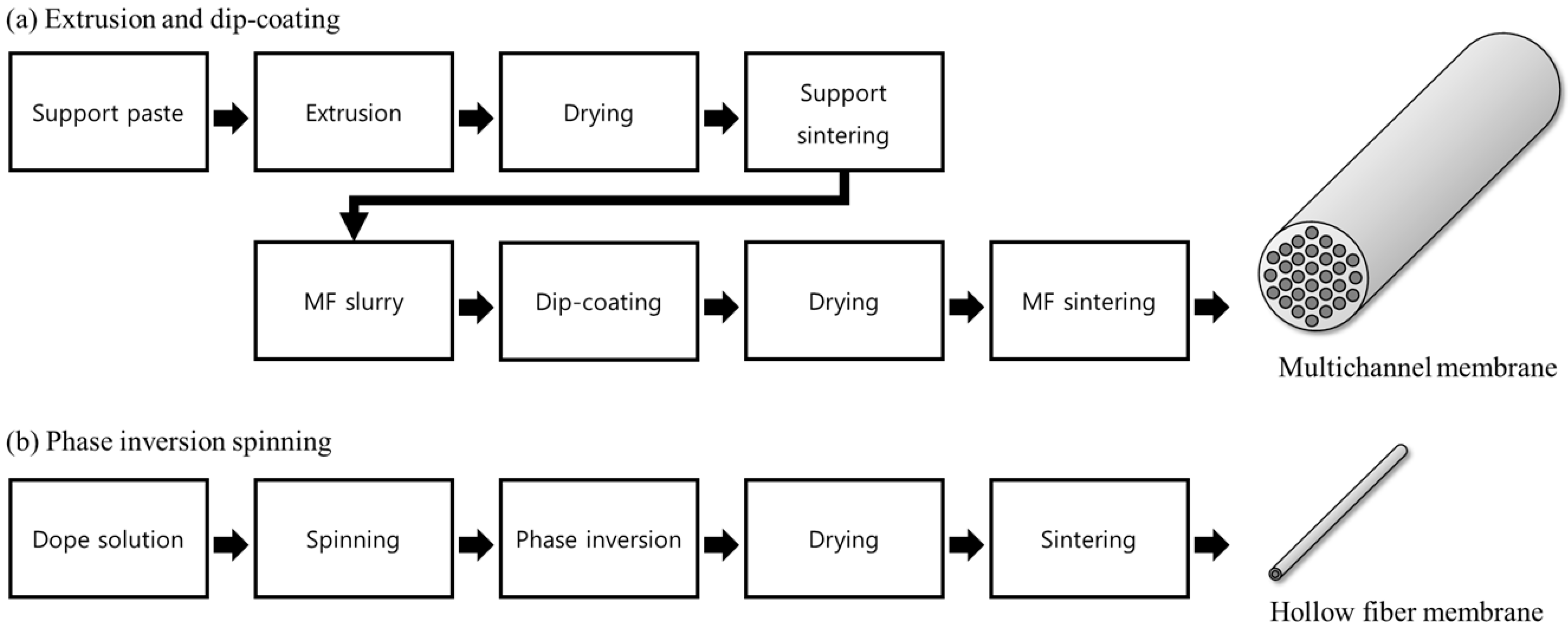
Figure 1 provides a schematic overview of the two membrane fabrication processes assessed in this study. As illustrated in
Figure 1a, the multichannel ceramic membrane manufacturing process involves the preparation of an alumina-based support paste, which is extruded to form a tubular support structure. High-purity α-Al
2O
3 powder (average particle size = 4.8 μm, AM-210, Sumitomo Chemical Co., Tokyo, Japan) was employed to prepare the ceramic support paste. The powder was first dry-blended with methyl cellulose (5 wt%, Sigma-Aldrich, St. Louis, MO, USA) as a binder, followed by the addition of deionized (DI) water (11 wt%) as the main solvent and polyethylene glycol (PEG, MW = 400, 1 wt%, Sigma-Aldrich, St. Louis, MO, USA) as a plasticizer. The mixture was allowed to equilibrate at ambient temperature for 48 h before being processed through a twin-screw extruder (KTE-50S, Kosentech, Gyeonggi-do, Republic of Korea). The resulting green bodies had a tubular geometry (outer diameter = 24 mm) containing 30 parallel channels (each = 2.7 mm inner diameter). These specimens were dried at room temperature for 24 h and subsequently sintered at 1500 °C for 2 h. After drying and initial sintering (support sintering), a porous support with sufficient mechanical strength was obtained. Subsequently, a water-based MF slurry containing alumina particles and polymeric binders was prepared and applied to the support via dip-coating. For the microfiltration (MF) coating layer, sub-micron α-Al
2O
3 powder (average particle size = 0.27 μm, AKP-30, Sumitomo Chemical Co., Tokyo, Japan) was dispersed in a mixture of 2-propanol (Sigma-Aldrich, St. Louis, MO, USA) and DI water, together with polyvinyl alcohol (PVA, MW = 500, Junsei Chemical, Tokyo, Japan) as an organic binder. The resulting slurry was applied to the inner channel surfaces of the tubular supports, which were masked on the exterior, using a laboratory-scale dip-coating unit (EF-4300, E-flex, Gyeonggi-do, Republic of Korea) for 60 s at a withdrawal rate of 1 mm/s. The coated membranes were air-dried for 24 h, followed by final sintering at 1300 °C for 1 h with a controlled heating rate of 5 °C/min. After another drying step, the membrane underwent a second sintering process to achieve a final multichannel ceramic membrane. Although this method requires two separate sintering steps, its major environmental advantage lies in completely avoiding the use of organic solvents throughout the entire fabrication process.
Figure 1b illustrates the phase-inversion spinning process for the hollow fiber ceramic membrane. Initially, a dope solution consisting of alumina particles, polymeric binders (such as PESf), dispersant (e.g., PVP), and the organic solvent NMP was prepared. Commercial α-Al
2O
3 powder (average particle size = 1.1 μm, Sumitomo Chemical, Tokyo, Japan) was employed as the ceramic precursor for hollow fiber membrane fabrication. Polyethersulfone (PESf, Ultrason
® E6020P, BASF, Ludwigshafen, Germany) served as the polymer binder, while polyvinylpyrrolidone (PVP, Sigma-Aldrich, St. Louis, MO, USA) acted as a dispersant. N-methyl-2-pyrrolidone (NMP, 99.5%, Samchun Pure Chemical Co., Ltd., Gyeonggi-do, Republic of Korea) was used as the organic solvent. The formulation of the spinning dope was prepared with an Al
2O
3:NMP:PESf:PVP weight ratio of 120:67:12:1. The raw materials were blended under continuous mechanical stirring for approximately 36 h at room temperature to obtain a homogeneous suspension. The resulting dope solution was subsequently degassed under vacuum for 1 h to eliminate air bubbles generated during mixing. The dope solution was then extruded through a spinneret into a coagulation bath (typically water), causing rapid phase inversion and solidification of the fiber, resulting in a characteristic asymmetric structure featuring a finger-like macrovoid interior and a sponge-like porous exterior. For spinning, the dope solution was fed from a pressurized reservoir using N
2 gas, while ultrapure water (10 mL/min) was simultaneously introduced as the bore fluid through a syringe pump (Fusion 100, Chemyx, Stafford, TX, USA). The hollow fiber extrusion passed through an air gap of approximately 10 cm before entering the external coagulation bath (tap water). Fibers were maintained in the bath for 24 h to enable solvent–non-solvent exchange and complete phase inversion. The as-spun fibers were thoroughly rinsed with water to remove residual solvent, and then they were dried in an oven at 100 °C overnight. Finally, sintering was carried out in a muffle furnace at 1450 °C for 2 h to produce mechanically robust ceramic hollow fibers. This fabrication approach simplifies the process by requiring only one sintering step but mandates the use of considerable amounts of the hazardous organic solvent NMP, thereby increasing the potential environmental and health impacts.
Thus, the two membrane fabrication processes, despite using the same base material (alumina), exhibit distinct environmental profiles in terms of material usage, energy consumption, and waste generation. This study aims to quantitatively evaluate how these process differences influence the overall environmental sustainability of ceramic membrane production, thereby providing practical insights for environmentally preferable ceramic membrane fabrication methods.
2.2. Membrane Fabrication
These two fabrication processes not only influence the resulting pore structure and mechanical properties of the membranes but also differ significantly regarding raw material usage, energy consumption, and environmental impacts, all of which have been thoroughly analyzed in this study.
Table 1 summarizes the consumption of raw materials and the sintering conditions required to produce a unit membrane area of 1 m
2. Raw material usage data were based on actual laboratory-scale production and normalized per square meter of effective membrane area. The area-based weights reported in
Table 1 were determined from the mass of the membranes after sintering, when only alumina remained. During the sintering process, all polymeric binders and solvents are completely removed; therefore, the final mass corresponds solely to the alumina content. The dry mass of each sintered membrane was measured using an analytical balance (CAS, Gyeonggi-do, Republic of Korea) and divided by the total effective membrane surface area. For multichannel ceramic membranes, the effective surface area was calculated as the sum of the internal wall areas of all channels, based on the measured channel diameters and lengths. For hollow fiber membranes, it was calculated from the measured outer diameter and length of each fiber, multiplied by the total number of fibers. Since the formulation ratios of polymeric additives and solvents relative to alumina in the green body are fixed for each fabrication method, the corresponding initial masses of these organic components can be calculated in reverse from the measured alumina mass. This approach ensures that the calculated area-based weights inherently account for the contribution of all pore walls, as the effective membrane surface area calculation includes all internal channel surfaces for multichannel membranes and the full surface for hollow fiber membranes.
For the multichannel membrane, alumina usage was the highest at approximately 3073.1 g/m2, which appears greater than that of the hollow fiber membrane due to its lower surface area per unit volume, rather than excessive material consumption. In contrast, the hollow fiber membrane has a much smaller diameter, leading to a higher surface area-to-volume ratio and, therefore, requiring less alumina (approximately 1159.2 g/m2) per unit membrane area. In the multichannel process, methyl cellulose (MC) was used as a binder, while PVA and isopropanol (IPA) were employed in the preparation of the MF dip-coating suspension to enhance the coating uniformity and particle adhesion. The entire fabrication process used only water and IPA as solvents, without involving any toxic organic solvents. In contrast, the hollow fiber membranes were fabricated via a phase-inversion process using NMP as the primary solvent, with approximately 647.2 g/m2 consumed. The polymeric additives PESf and PVP were used at 115.9 g/m2 and 9.7 g/m2, respectively, to facilitate membrane formation and stabilize the pore structure. Although a large volume of water was used in the coagulation bath, this water was contaminated with NMP through solvent exchange during phase inversion, requiring subsequent wastewater treatment within the system boundary.
Regarding the sintering conditions, the multichannel ceramic membranes required two separate sintering steps: an initial sintering of the support layer at 1500 °C, followed by a second sintering step for the MF layer at 1300 °C. In contrast, hollow fiber membranes were manufactured through a single sintering step at 1450 °C. These differences in raw material consumption and sintering conditions directly impact energy consumption and associated carbon emissions, providing a critical basis for the environmental sustainability comparison of the two ceramic membrane fabrication routes.
2.3. Membrane Characterization
Various characterization methods were employed to evaluate and compare the structural properties and filtration performance of the fabricated multichannel and phase-inversion hollow fiber ceramic membranes.
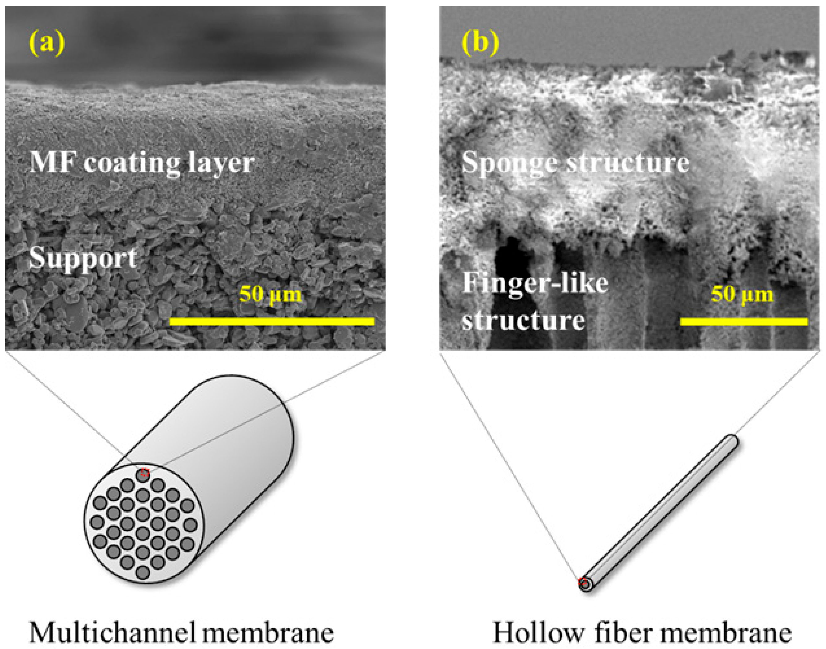
First, the cross-sectional microstructures of the membranes were observed using scanning electron microscopy (SEM, SNE-4500 M, SEC Co., Ltd., Gyeonggi-do, Republic of Korea). For the multichannel ceramic membranes, cross-sectional samples were prepared by cutting the tubular membranes to expose both the inner and outer surfaces. These samples were coated with platinum prior to SEM analysis. Similarly, hollow fiber membranes were sectioned to obtain cross-sectional views under identical SEM conditions. The SEM images were used to qualitatively evaluate the porous structure, coating layer thickness, and structural asymmetry of each membrane type.
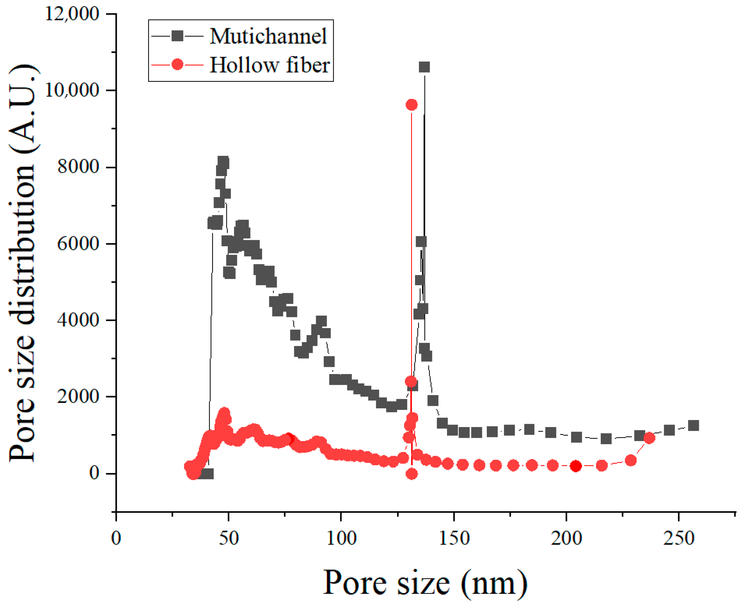
The pore size distributions of the membranes were quantitatively measured using a capillary flow porometer (CFP-1100, PMI, New York, NY, USA) with Galwick® (surface tension = 15.9 dyn/cm) as the wetting liquid. Prior to measurement, the instrument was factory-calibrated by the manufacturer using certified reference membranes. In this analysis, membrane samples were mounted under identical conditions and saturated with a wetting liquid. Gas was then applied incrementally, and the pressure required for gas penetration through membrane pores was measured to determine the pore size and pore size distribution. The average pore sizes for both the multichannel and hollow fiber membranes were found to be in the range of approximately 100–150 nm, confirming their suitability for microfiltration (MF) applications. Pore size distribution curves were primarily used to compare the dominant pore size and the breadth of pore size distributions between the two membrane types.
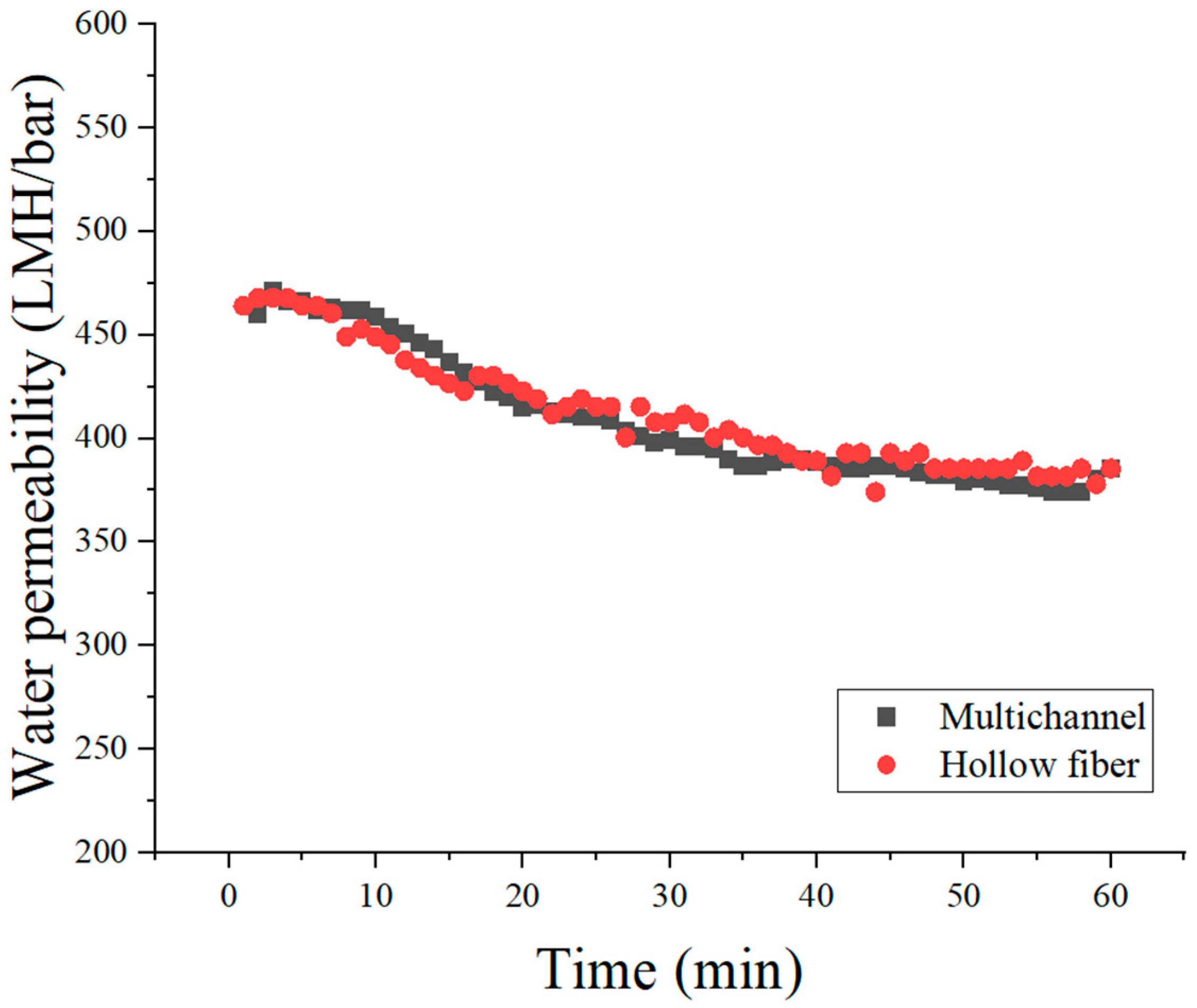
Filtration performance, specifically water permeability, was assessed using a constant-pressure filtration apparatus (SepraTek, Daejeon, Republic of Korea). Membrane samples were mounted in a filtration cell, and pure water flux was measured at a constant applied pressure of 2 bar and at a controlled temperature of 25 °C. Permeate flux values, representing the amount of water permeating per unit membrane area per hour, were determined after initial stabilization of the flux rate. These measurements enabled direct comparison of water permeability between multichannel and hollow fiber ceramic membranes.
Through this comprehensive characterization approach, the structural similarities and differences between the two ceramic membranes, along with their fundamental filtration performance, were systematically analyzed. These results served as a crucial reference point for subsequent environmental impact evaluations.
2.4. Carbon Footprint Analysis
In this study, the environmental assessment is limited to global warming potential (GWP100), expressed as CO2-equivalent emissions. This focus was chosen for two main reasons: (i) CO2-equivalent emissions are the most standardized and widely reported indicator for environmental performance, enabling robust comparison between different manufacturing routes; and (ii) consistent and high-quality life-cycle inventory data for other environmental categories, such as water usage, ecotoxicity, and resource depletion, are scarce for ceramic membrane fabrication processes. Expanding the scope to multiple impact categories would require additional primary data collection and a broader inventory, which is beyond the scope of the present work. Nevertheless, the methodological framework established here can be readily extended in future studies to include additional LCA indicators for a more holistic evaluation.
In this study, an inventory analysis was conducted based on the raw materials and energy consumption involved in the fabrication processes of multichannel ceramic membranes and phase-inversion hollow fiber membranes. The inventory data were derived from actual laboratory-scale fabrication experiments and normalized per 1 m2 of effective membrane area to enable a direct comparison of environmental impacts between the two different membrane manufacturing processes.
Table 1 summarizes the types and quantities of raw materials consumed in each fabrication route. For the multichannel ceramic membrane, the primary raw materials included alumina powder, methyl cellulose (MC), polyvinyl alcohol (PVA), isopropanol (IPA), and water, with alumina accounting for the largest portion as the main component of both the support and MF coating layers. In contrast, the hollow fiber membrane fabricated via the phase-inversion method utilized relatively smaller amounts of alumina but required substantial quantities of the organic solvent N-methyl-2-pyrrolidone (NMP) and polymeric additives, including polyethersulfone (PESf) and polyvinylpyrrolidone (PVP). The environmental impacts arising from raw material production and energy consumption were evaluated based on carbon emissions. The carbon emission factors for the raw materials employed are presented in
Table 2.
These emission factors were obtained from the relevant literature and publicly available databases, reflecting cradle-to-gate values. For alumina (Al
2O
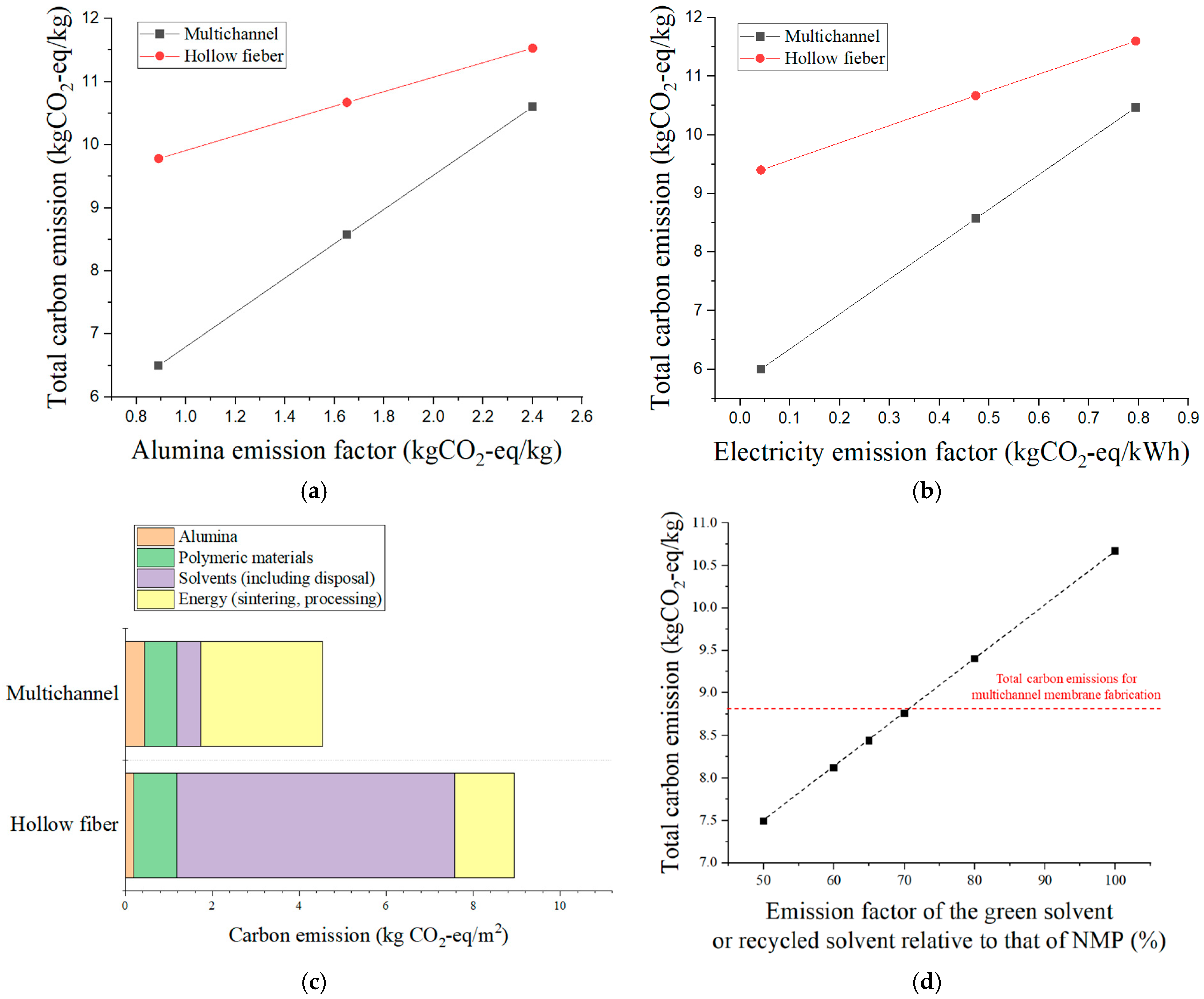
3), the literature reports a wide range of cradle-to-gate carbon emission factors, from 0.89 to 2.40 kg CO
2-eq/kg, depending on the production route, particle size, powder flowability, and the energy source used in the Bayer process [
25]. For example, hydropower-based refining processes have been reported at the lower end of the range (~0.89 kg CO
2-eq/kg), while coal-fired processes can reach values as high as ~2.40 kg CO
2-eq/kg. Intermediate values, such as 1.44–1.72 kg CO
2-eq/kg, are associated with natural gas-based or thermal-energy Bayer processes [
26]. In this study, we adopted a representative value of 1.65 kg CO
2-eq/kg, which lies within the reported range and reasonably reflects the average for commercially available Al
2O
3 powders. This representative value was applied to both membrane fabrication routes to ensure a consistent basis for comparison. To account for the variability in this parameter, a sensitivity analysis was conducted by applying the lower- and upper-bound values from the literature range. For NMP, the carbon emissions associated with wastewater treatment were also considered. The wastewater stream was assumed to consist of the water used as a coagulation bath and the residual NMP from the dope solution, which was treated by incineration [
33]. For PVP, a direct cradle-to-gate carbon emission factor could not be found; therefore, we referred to the literature reporting emission factors of similar polymeric materials in the range of 7–8 kg CO
2-eq/kg and adopted the mid-value of 7.5 kg CO
2-eq/kg [
30]. Since PVP was used only in trace amounts as a dispersant, contributing less than 0.1% to the total carbon footprint, the use of this approximate value was deemed acceptable. For electricity, the 2024 emission factor was used, and the global average value was applied for the base scenario [
34]. In the sensitivity analysis, we also evaluated the impact of electricity emission factor variability by considering the average values from the five lowest-emission countries (Norway, Switzerland, Sweden, France, and Costa Rica; primarily renewable-based energy mixes) and the five highest-emission countries (Kosovo, Kazakhstan, Mongolia, South Africa, and India; fossil fuel-dominated energy mixes). This approach enabled us to assess the influence of extreme variations in electricity grid carbon intensity on the overall carbon footprint results.
The electricity consumption for the sintering process was estimated based on the rated power of the muffle furnace (28 kW, ST-1600, SentroTech, Strongsville, OH, USA; chamber volume ≈ 100 L) and the heating schedule for each firing cycle. For the support sintering process (1500 °C), the heating and holding durations were 295 min and 120 min, respectively. For the MF membrane (1300 °C), the heating and holding times were 255 min and 60 min, respectively, while for the hollow fiber membrane (1450 °C) they were 285 min and 60 min, respectively. All processes were followed by natural cooling without active heating.
While a simple nameplate-based calculation (rated power × total heating time) assumes continuous full-power operation and, thus, overestimates the actual consumption, the furnace typically operates at full power during the heating ramp and at a reduced duty cycle during the holding stage. In this study, we assumed 100% of rated power during the heating stage and 55% of rated power during the holding stage, which reflects typical operating conditions for laboratory-scale muffle furnaces.
The total electricity consumption (kWh) for each sintering cycle was calculated as follows:
where P
rated is the furnace’s rated power (kW), and t
heating and t
holding are the heating and holding times (h), respectively. Based on this approach, the total energy consumption per sintering cycle was approximately 606 MJ (168 kWh) for the support sintering, 484 MJ (134 kWh) for MF membrane sintering, and 534 MJ (148 kWh) for hollow fiber membrane sintering.
Under our loading conditions—less than 50% of the chamber volume filled per firing cycle—each sintering batch yielded approximately 51 m2 of membrane area. The total energy consumption per unit membrane area (MJ/m2) was therefore obtained by dividing the total batch energy (MJ) by the processed membrane area (51 m2). Based on this approach, the specific energy consumption values were approximately 11.9 MJ/m2 for the support sintering, 9.5 MJ/m2 for MF membrane sintering, and 10.5 MJ/m2 for hollow fiber membrane sintering.
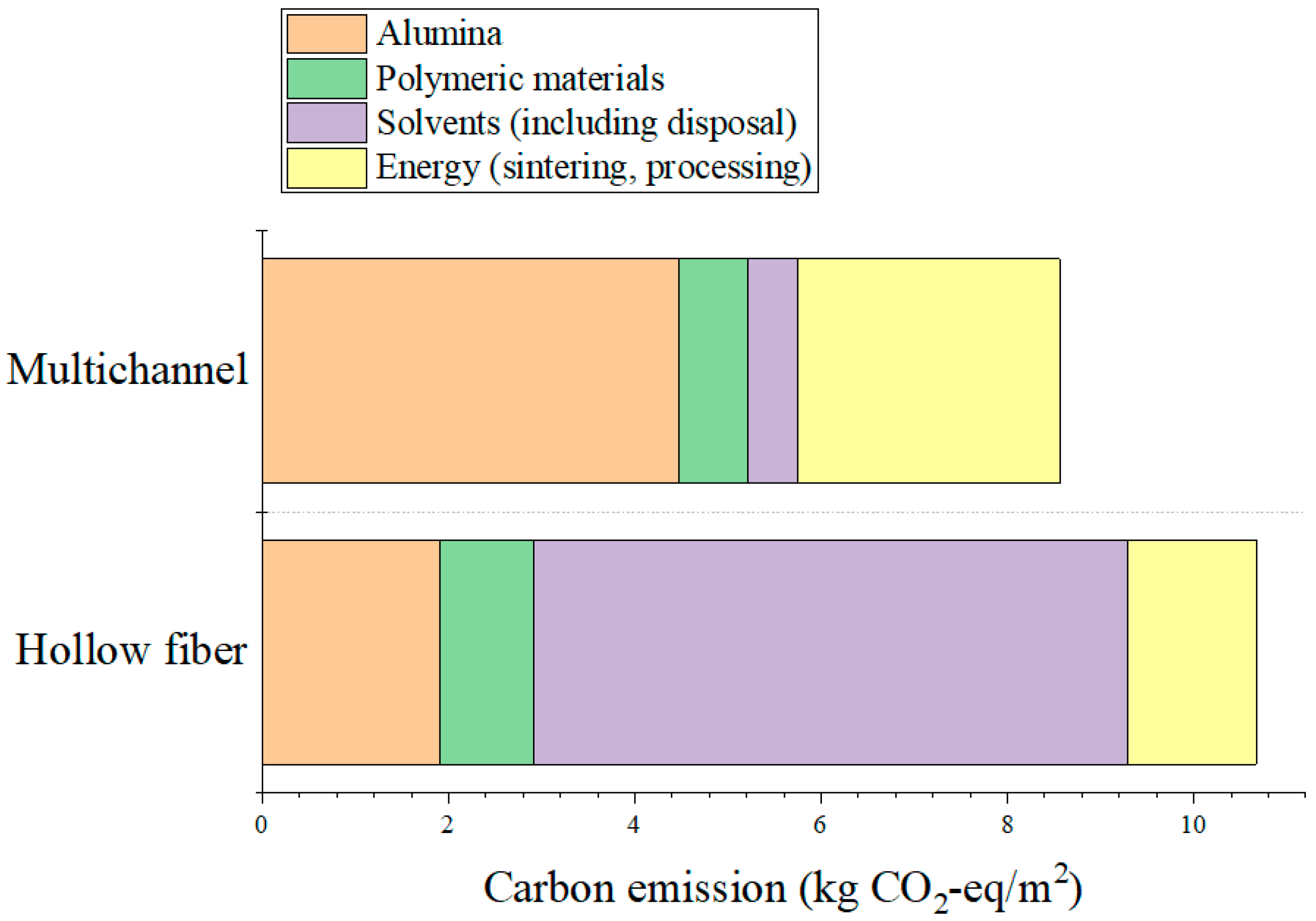
Based on the inventory analysis and carbon emission factors, carbon emissions resulting from the consumption of raw materials and energy were calculated for each manufacturing process. This provided a quantitative basis for comparing the relative environmental impacts between the two ceramic membrane fabrication methods.
