Abstract
Membrane technology is widely used in various aspects of wastewater treatment; however, single membrane technology has a series of disadvantages, such as high selectivity, poor recycling performance, and susceptibility to contamination. In this study, a treatment method combining an advanced oxidation process and membrane separation technology was proposed, and a geopolymer-based Fenton-like catalytic tubular membrane (GFM) was prepared by using H2O2 as a blowing agent by the direct foaming method. It was shown that the optimum conditions for the preparation of the membrane were a water glass modulus of 1.8 M, the addition of foaming agent of 1 mL, and a thickness of the membrane of 6.5 mm, with a flux of 6942 L·m−2·h−1. Due to the characteristics of the tubular membrane, the possibility of adding hydrogen peroxide directly inside the membrane allows an optimal Fenton-like removal, which is better than outside the membrane, thus reducing the consumption of hydrogen peroxide. The tubular membrane has a multi-stage porous structure, high flux, and a high specific surface area (68.74 m2/g). The GFM/H2O2 Fenton-like system formed is capable of almost completely degrading all kinds of synthetic dyes under various stringent conditions, and the XRD, FTIR, and TG analyses and cycling tests showed that the GFM has excellent stability and a significant advantage in terms of reusability.
1. Introduction
Currently, global tensions over water issues are rising, and the sustainable management of water resources is essential to maintaining prosperity and peace in the world. It has been reported that about 8 × 10⁵ tons of synthetic dyes are generated globally each year, and this amount is expected to continue to grow [1], especially as the rapid development of various application industries, such as textiles, paints and coatings, construction, and plastics, generates large amounts of dye wastewater, making it difficult to deal with the large amount of wastewater discharges [2], These discharges consist of a variety of organic and inorganic pollutants that contaminate water bodies and soils, destroy aquatic ecosystems, and jeopardize human health. Dye wastewater is considered a persistent pollutant, causing serious negative impacts and thus attracting widespread attention [3,4].
So far, the methods used to remove dye wastewater include flocculation [5], activated carbon adsorption [6], microbial degradation [7], membrane separation [8], electrocatalysis [9], and advanced oxidation processes (AOPs) [10]. Although each of these methods has its advantages, such as the ease of operation and low cost of flocculation, and the high efficiency of activated carbon adsorption, they also have certain limitations [11]. Among them, membrane separation technology is a technique that has been widely used in water purification technology [12], with the advantages of small equipment size, simple operation, high removal effect, and low cost [13]. However, membrane separation technology is easily affected by fouling during long-term use, leading to pore clogging and membrane contamination [14]. Furthermore, membrane filtration can only effectively remove the color through physical retention, adsorption, or electrostatic rejection, the dye molecules will not be degraded and instead become concentrated, requiring additional treatment processes. Because of their low permeability, non-pressure-driven membrane processes (such forward osmosis) are rarely discussed even though they have a low tendency to foul [15]. As a result, it is crucial to address these challenges in the membrane separation process.
Fenton technology plays a crucial role in advanced oxidation processes (AOPs). It effectively degrades various dyes in wastewater non-selectively through powerful oxidants like hydroxyl radicals, which are generated by hydrogen peroxide and iron ion catalysts. This is generally considered to be the most effective treatment method [16]. By combining Fenton-like catalytic technology with membrane separation technology, membranes with catalytic functions can be prepared. These membranes can quickly direct pollutants to active sites on the membrane surface, improving reaction velocity and enhancing the efficiency of the membrane separation process. Additionally, the mineralization function of the membrane helps degrade pollutants, enhancing its anti-fouling performance and effectively preventing membrane contamination, thus addressing the shortcomings of traditional membrane separation technology. Compared with other systems like photocatalysis, photo-Fenton, and ozonation treatment, Fenton technology is more affordable and advantageous [17]. Non-homogeneous Fenton-like systems produce less iron sludge and fewer residual products than homogeneous Fenton, reducing secondary contamination. In particular, non-homogeneous Fenton is more capable of treating dye wastewater in stringent environments, achieving highly efficient removal [18,19]. Research on Fenton-like catalyst membranes for the treatment of dye wastewater has gained increasing attention. Naiku Xu et al. [20] prepared polyacrylonitrile (PAN)/poly(acrylic acid) (PAA) composite nanofibrous membranes and loaded them with iron ions using layer-by-layer sequential electrostatic spinning. These membranes, used with hydrogen peroxide to form a Fenton-like system, demonstrated a removal efficiency of methylene blue (MB) up to 97.0% over 30 operating cycles. Chen et al. [21] synthesized powdered MnO2/C-CNT using a hydrothermal process and then used vacuum-assisted filtration coupled with PVDF to prepare MnO2/C-CNT@poly (vinylidene fluoride) (PVDF) membranes. These membranes achieved the complete removal of the organic dyes MB and Rh B primarily through 1O2 radical oxidation, and they maintained an excellent cycling stability.
An appropriate carrier can improve the ease of operation, structural stability, and affordability of catalytic materials. The phrases “geopolymer” and “geopolymerization” were first used by Davidovits in 1972 [22]. Geopolymer is an inorganic polymer gel material with a three-dimensional network structure obtained by the hydrolysis–condensation reaction of aluminosilicates activated by alkaline solutions [23]. Its properties are similar to those of ceramics, but when compared with traditional cement, ceramics, and organic polymers, it has superior mechanical strength properties and chemical resistance, low cost, and low CO2 emissions, which are of great significance for both actual industrial production and meeting the requirements of sustainable development. In addition, it is an excellent catalyst carrier material since it can effectively immobilize the metal ions [24]. Huang et al. [25] prepared a biochar/geopolymer composite catalyst membrane (BC/GM) with hydrogen peroxide to produce hydroxyl radicals capable of degrading nearly 100% of tetracycline (pH 5.0, 60 °C, 5 h) through an in situ simultaneous carbonization and self-activation process. He et al. [26] prepared a graphene oxide GO/geopolymer with a super-hydrophilic multifunctionality by utilizing a fly ash composite membrane coupled with photocatalytic degradation to remove MB, and the removal efficiency reached 84% at 120 min under light conditions. Therefore, porous geopolymer materials have great potential for wastewater treatment due to their suitable porous structure and metal immobilization ability. However, studies on geopolymer-based catalyst tubular membranes for dye wastewater treatment have not yet been published.
In this study, a geopolymer-based Fenton-like catalyst tubular membrane loaded with iron ions was prepared by combining an advanced oxidation process and membrane technology. In the dye wastewater degradation experiment, due to the characteristic of tubular membrane, compared with other separation membranes or catalysts, the membrane can pass hydrogen peroxide into the channel of the tubular membrane and directly contact the tubular membrane and then undergo a Fenton-like reaction, which can reduce the consumption of hydrogen peroxide, which has certain economic value in practical engineering. Additionally, this research provides environmentally friendly materials and preparations and alleviates the problem of dye emissions in industrial applications. Additionally, it tests the membranes’ ability to remove multiple synthetic dyes from wastewater under different conditions, and it aims to provide an efficient and environmentally friendly method for dye wastewater treatment. The goal is to overcome the shortcomings of existing technologies and promote practical progress in industrial applications.
2. Material and Methods
2.1. Experimental Materials and Reagents
The granulated blast furnace slag used in this study was provided by Guangxi Beihai Chengde Group, and its chemical composition and content are listed in Table 1. Sodium silicate, potassium silicate, and sodium hydroxide (96%) were purchased from Foshan Zhongfa Water Glass Company Ltd. (Foshan, China) in Guangdong Province, and ferric nitrate nine hydrate, hydrogen peroxide (30 wt.%), and sodium dodecyl sulphate were purchased from Guangdong Guanghua Science and Technology Company Limited. Crystalline violet (CV), rhodamine B (Rh B), and methyl orange (MO) were purchased from Shanghai Macklin Biochemical Technology Co. (Shanghai, China). The deionized water was produced by the laboratory of the School of Chemistry and Chemical Engineering, Guangxi University.

Table 1.
Main chemical composition and content of slag.
2.2. Preparation of Catalytic Tubular Membrane
The modulus of the sodium water glass was 1.3 M (17.94 g NaOH, 100.00 g industrial 3.37 M water glass) and 1.8 M (200.00 g Na2SiO3, 165.20 g H2O, 43.824 g NaOH). An amount of 25 g of slag, 30 g of sodium water glass, and 5 g of potassium silicate were mixed and stirred at 800 rpm for 5 min to obtain GM. After mixing, 5 g of ferric nitrate hydrate (which melted to liquid at 100 °C), 0.04 g of surfactant K12, and finally different proportions of H2O2 were added sequentially, and the mixture continued to be stirred (1500 r pm, 1 min). The homogeneous slurry was poured into polypropylene plastic molds of different sizes (17, 21, 25, and 30 mm in diameter at the bottom of the cylinder, respectively). Polypropylene rods (6, 8, and 10 mm in diameter) were inserted into the center, and their positions were fixed with perforated rubber plugs. The molds were placed in an oven at 60 °C for foaming and maintenance (the rods were removed after 20 min) and continued to be cured for 24 h. The catalytic tubular membrane was obtained after demolding. The preparation flow chart is shown in Figure 1a.
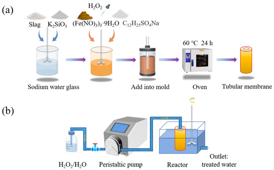
Figure 1.
(a) Process flowchart for the preparation of the geopolymer-based Fenton-like catalyst tubular membrane; (b) schematic diagram of the dye degradation device in the intermittent membrane reactor.
2.3. Experimental Equipment and Apparatus
The physical composition of the samples was analyzed by X-ray diffraction (Rigaku MineFlex, Rigaku, Kyoto, Japan). The molecular structure and functional group changes of the samples were detected by Fourier transform infrared spectroscopy (Nicolet IS50, Thermo Scientific, Waltham, MA, USA). The morphology and elemental composition of the samples were observed using a scanning electron microscope (TESCAN MIRA LMS, Brno, Czech Republic) connected to an energy spectrum analyzer. Specific surface area and mesoporous pore size distribution of the samples were determined using a Gemini VII2390 (Micromeritics, Norcross, GA, USA). Sample cross sections were captured and analyzed using image j image analysis software to obtain the macroporous pore size distribution of the samples. The TG-DSC (STA 449 F3 Jupiter, NETZSCH, Selb, Bavaria, Germany) was used to characterize the temperature–mass change relationship and the rate of change of the samples. The chemical state and structural analysis of the elements of the samples and their relative content variations were studied using X-ray photoelectron spectroscopy (Thermo Scientific K-Alpha, Waltham, MA, USA).
In addition, the surface hydrophilicity of the membrane was evaluated using a water contact angle measurement device (JY-82C Video Contact Angle Measuring Instrument, Chengde Dingsheng, China). The hydrophilicity of the membrane could be determined by measuring the contact angle formed by water droplets with the membrane surface. The free radicals generated during degradation were captured using paramagnetic resonance spectroscopy (Bruker EMXPLUS, Saarbrücken, Germany).
Bulk density was measured using the geometric method, the homogeneous slurry was poured into a regular mold with a length, width, and height of 2 cm × 2 cm × 2 cm, three dried specimens were weighed to obtain the average value of m1, the diameter and thickness of each specimen were measured with vernier calipers, the volume of the specimen was calculated to obtain the average value, and the volume density ρ1 was obtained by the calculation of the following Equation (1) (the unit is g⋅cm−3):
The true density was measured using the gravimetric bottle method, which is similar to the gravity bottle. A certain mass m2 of powder was poured into the bottle for 10 min, and then the volume of powder v2 was measured. Its true density ρ2 was calculated from the following Equation (2) (the unit is g⋅cm−3):
According to Equation (3), the sample porosity (α) can be calculated as follows:
2.4. Study on Dye Wastewater Removal Efficiency
The membranes were evaluated by intermittent catalytic degradation experiments of several soluble dye wastewaters commonly used in the textile industry by geopolymer-based Fenton-like catalyst tubular membranes. The prepared membranes were washed with deionized water to remove the excess alkali in the samples to prevent the hydrogen peroxide from being consumed by the alkali in large quantities when entering the membrane interior, and the water flux and dye wastewater degradation performance of the membranes were tested by the simple membrane device made in the laboratory. The experimental setup is shown in Figure 1b, and the water flux was calculated by using the following Equation (4) [27]:
where J (kg·m−2·h−1) is the water flux, m (kg) is the mass of water, A (m2) is the effective filter area, and t (h) is the infiltration time. The membrane was immobilized in a device filled with dye wastewater (100 mL–2000 mL, 10–100 mg/L) in an intermittent reaction vessel, and H2O2 was passed through the hollow pipe of the membrane with simultaneous stirring, and the removal efficiency of the various dyes (CV, Rh B, and MO) were experimentally determined in different acidic and alkaline environments (pH = 3, 7, and 9) and at different temperatures (T = 25, 35 and 45 °C).
To measure the concentration of dyes in synthetic dye wastewater, a UV-visible spectrophotometer (UV 3600 Plus, SHIMADZU Corporation, Kyoto, Japan) was used. Measurements were made at the wavelength corresponding to the maximum absorbance (λmax) of the dyes. The maximum wavelengths of crystalline violet, rhodamine B, and methyl orange were 580 nm, 555 nm, and 467 nm, respectively. The removal efficiency of the dyes for the performance of GFM was calculated by the following Equation (5):
where C0 (mg·L−1) is the initial concentration of the dye, and Ct (mg·L−1) is the concentration of the dye after the degradation reaction.
The stability and reusability of membranes were evaluated by a cycling test, in which the membrane was dried in an oven and recycled.
3. Results and Discussion
3.1. Study of the Preparation Conditions of Tubular Membranes
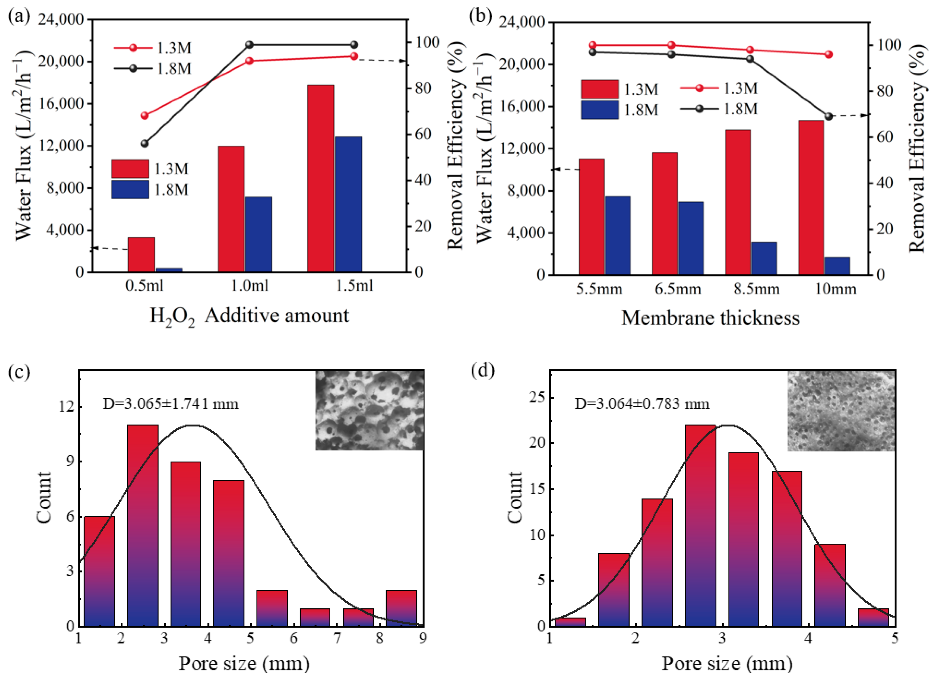
In the laboratory-made intermittent reaction device, the hollow tubes of the prepared membranes were inflowed with H2O2, a Fenton-like reaction occurred when it came in contact with the membranes, and it broke down the pollutants. We used CV wastewater as a pollutant to experimentally study the optimal preparation conditions. In this process, the water flux becomes a key factor determining the performance of the membranes. The membranes with various water fluxes and stable microstructures can be obtained by altering the preparation conditions [28]. As shown in 2a, with the increase of H2O2 amount, the inorganic membrane’s water flux rose steadily. This is because H2O2 is decomposed rapidly in the presence of a strong alkali to release oxygen, and the more oxygen released in the mixed slurry, the larger the inorganic membrane’s pore diameter, which leads to an impact on the flux. Figure 2b shows that the thickness of membrane also had a certain effect on the flux. However, contrary to the 1.3 M membranes, the flux of the 1.8 M membranes decreased with the increase of membrane thickness, which may be attributed to the fact that, as the membrane thickness increased, the amount of water adsorbed on it increased. The large pore of the 1.3 M membranes counteracted this unfavorable factor to maintain the flux, and the fact that 1.8 M membranes’ flux was significantly lower than the 1.3 M membranes’ is equally strong evidence of this point, which is confirmed in Figure 2c,d.It can be seen that the average pore size for the 1.8 M membrane was 3.0 mm, while the average pore size for the 1.3 M membrane was 3.7 mm. The results (Figure 2a,b) showed that the flux would limit the dye removal performance of the membrane to a certain extent. At 0.5 mL of H2O2, the flux of the 1.8 M membrane was 383.2 L·m−2·h−1, and its final efficiency of dye removal was merely 54%, while when the H2O2 added was 1.0 mL and the membrane thickness was 8.5 mm, the flux of the 1.8 M GFM was 3142 L·m−2·h−1, and it hardly affected the removal efficiency. However, considering that the membrane thickness leads to an increase in sample volume and loss rate, the larger the pore size, the higher the water flux, which means that the compressive strength of the inorganic membrane decreases [29]. Eventually, the tubular membrane with sodium water glass of 1.8 M, an H2O2 addition of 1.0 mL, and a membrane thickness of 6.5 mm was selected for the next studies (abbreviation GFM), and its water flux was 6942 L·m−2·h−1, which helped with to the dye removal performance.

Figure 2.
The water flux and removal efficiency of dyes of 1.3 M membranes and 1.8 M membranes with (a) different levels of H2O2 (membrane thickness = 6.5 mm); (b) different membrane thicknesses (H2O2 =1.0 mL); the pore size distribution of (c) 1.3 M membrane (D = 3.65 mm); (d) 1.8 M membrane (D = 3.06 mm).
3.2. Study on Dye Wastewater Removal Efficiency of GFM
The removal efficiency of CV, Rh B, and MO with the input of H2O2 inside and outside the membrane is demonstrated in Figure 3. It is evident from the data that the removal of dyes in general increased with the increase of H2O2 input. When 0.5 mL of H2O2 was added inside and outside the membrane, the removal efficiency of CV was 57.6% inside the membrane and 55.6% outside the membrane; when 2 mL of H2O2 was added, the removal rate of CV was 99.2% inside the membrane and 98.1% outside the membrane. It was observed that, under all conditions of H2O2 input, the dye removal efficiency was consistently higher within the membrane compared to the exterior. This finding suggests that the augmentation of H2O2 inputs results in the generation of a greater number of reactive oxides, thereby exerting a favorable influence on the removal efficiency of both CV and Rh B. The results demonstrated that the dye removal efficiency within the membrane was superior to that outside the membrane, which can be attributed to the increase in the number of reactive oxides produced by the elevated H2O2 inputs. The removal effect inside the membrane was better than outside the membrane and may be related to the increased propensity of H2O2 to interact and react with pollutants within the membrane environment. Furthermore, the findings revealed that the addition of H2O2 inside and outside the membrane did not exhibit a substantial difference in the degradation of MO, which may be associated with its negative charge and weak binding capacity with the membrane. The surface of geopolymer is abundant in hydroxyl groups, which partially ionize the surface in the solution to render it negatively charged and more likely to adsorb positive ions [30]. Additionally, due to the chemical stability of MO itself, the oxidative reaction is not significant compared to the other two dyes.
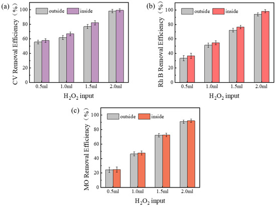
Figure 3.
Effects of adding H2O2 inside and outside the membrane on dye removal efficiency: (a) CV, (b) Rh B, (c) MO.
According to the experimental results, the addition of hydrogen peroxide inside the membrane is more likely to cause membrane clogging, nanoscale pore reduction, and porosity reduction, while the addition of hydrogen peroxide outside the membrane has almost no effect on the pore size of the membrane, but it is easy to make the membrane break from the center and lead to membrane damage.
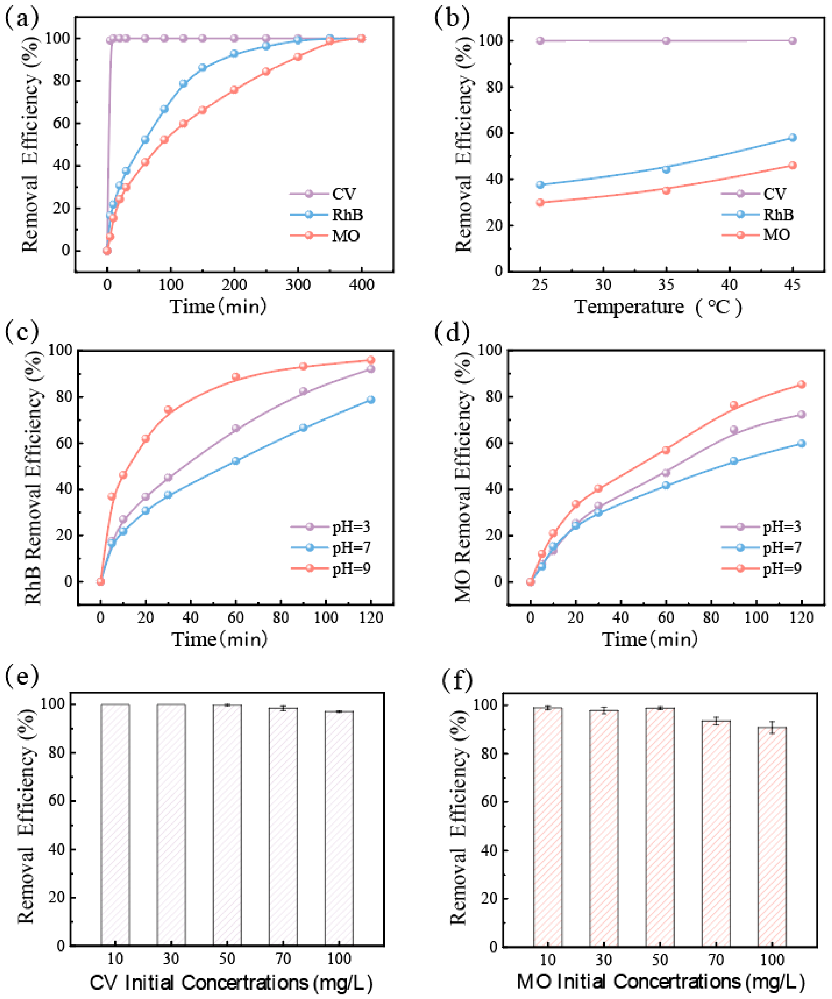
In order to evaluate the practical application of GFM, dye removal performance was tested in different environments. As shown in Figure 4a, several kinds of dye wastewater were effectively degraded by GFM in the intermittent reactor. Of them, the removal efficiency of CV reached 100% in 5 min, while Rh B and MO were slower, but the removal efficiency could reach more than 99% by the end of the degradation. The pH and temperature had a great influence on the degradation performance of the catalyst in the Fenton-like reaction. As shown in Figure 4b, the test explored the effect of temperature on the removal efficiency of dyes by GFM, and the absorbance of dye wastewater was measured 30 min after the reaction. When compared to room temperature, the rate of CV removal was barely enough time to observe the change due to the excessively rapid performance, whereas the removal efficiency of Rh B and MO increased by almost 20% at 45 °C. It can be seen that the higher temperature is beneficial to the catalytic reaction, and an appropriately elevated temperature can accelerate the degradation rate of dye wastewater. Moreover, since the Fenton-like reaction typically requires an acidic environment, Figure 4c,d illustrates the removal efficiency of CV, Rh B, and MO in various pH environments. These three dyes were effectively degraded over a wider pH range (3–9), and it was discovered that GFM degraded more quickly at low and high pH levels than in neutral environments, which is conducive to showing its potential for application in actual wastewater treatment. Figure 4e,f further depicts the effect of the initial concentration of dye on the removal efficiency, and it tended to decrease as the initial concentration of dye increased due to the fact that, with other conditions being equal, the activated oxygen produced was limited and could only degrade a certain number of dye molecules. When the initial concentration reached 100 mg/L, the removal efficiency was still stable at 90%.
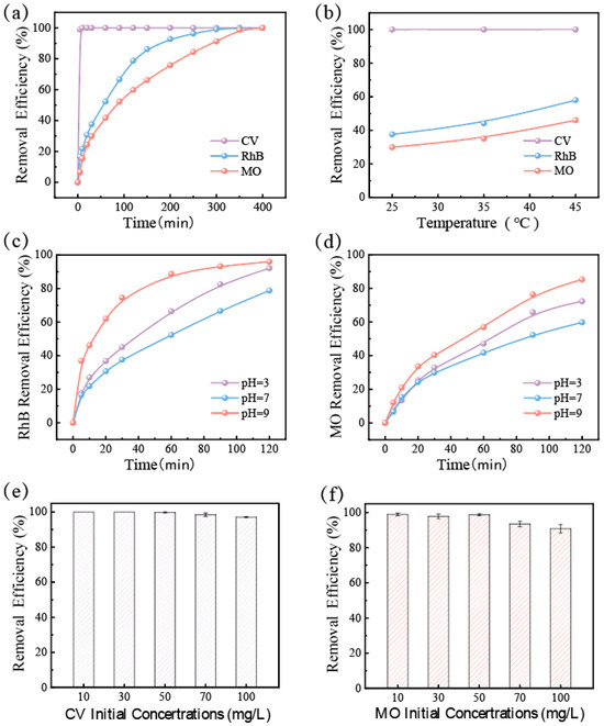
Figure 4.
For GFM: (a) removal efficiency curves of different dyes (CV, RhB, and MO) within 400 min; (b) removal efficiency curves of different dyes (CV, RhB, and MO) at different temperatures (30 min after reaction); removal efficiency of the dyes (c) MO and (d) RhB in different pH environments; removal efficiency of the dyes (e) CV, (f) MO in different initial concentrations.
3.3. Characterization of GFM
The structure of GFM can be classified into two components: the porous interior and the dense surface. Figure 5a shows a cross-sectional SEM image of GFM. It can be clearly seen that the interior of GFM is filled with macropores and mesopores of different sizes. GM was foamed to create a porous structure, and these pores were randomly distributed inside the tubular membrane. The pore reaction and iron ion loading resulted in pore clogging and collapse, which could make a stable gradient porous structure with high flux and provide more active sites. Otherwise, the pore shapes of inorganic membranes prepared from sodium water glass are regularly spherical [31], which is also reflected in the above Figure 5a. Figure 5b,c shows the outer surface of the GFM cylinder and the inner surface of the hollow tube, respectively. The GFM’s mouth and dense outer structure improve the hardness and resistance of the membrane and provide more operability for the GFM in practical engineering applications. Figure 5d,e presents the energy spectrum mapping of the GFM’s section and outer surface. It reveals a more uniform distribution of the elements in the sample, indicating that the slurry was thoroughly mixed and that the Fe element was successfully loaded, and its content was slightly higher in the interior of the membrane than on the surface.
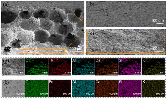
Figure 5.
The SEM images: (a) cross-sectional of GFM; (b) outer surface of GFM (i.e., the support layer); (c) inner surface of GFM (hollow tube); EDS of (d) cross-sectional and (e) outer surface.
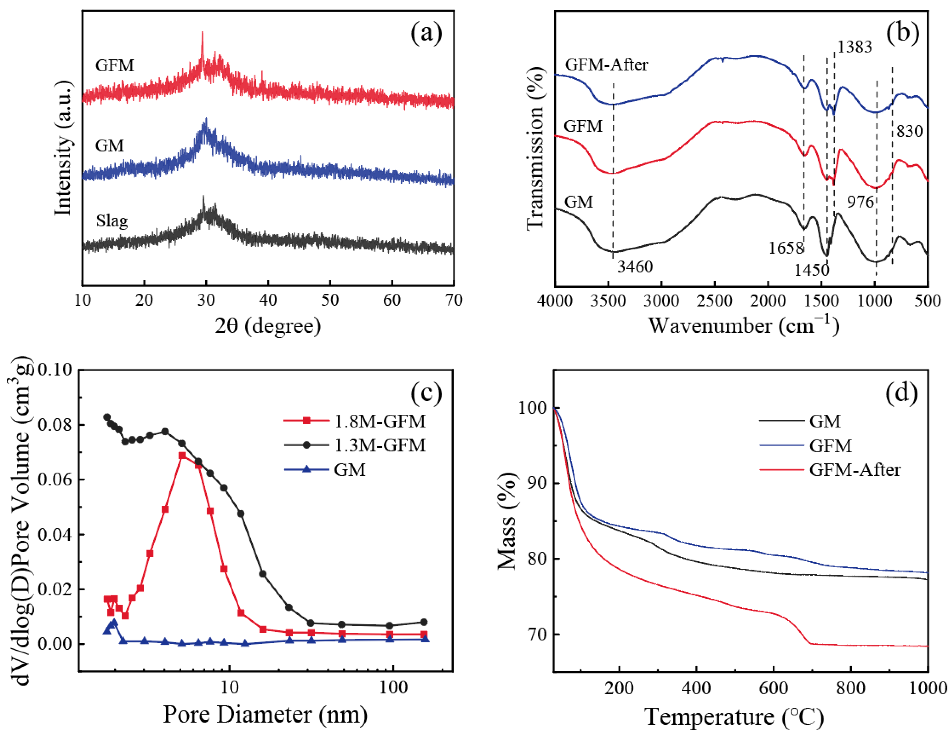
The X-ray diffraction patterns of samples are shown in Figure 6a. Slag and GM show a broad diffuse peak at 2θ = 20–35°, which is a typical characteristic peak of amorphous aluminosilicates [32]. After doping with iron, the GFM did not produce new crystalline phases and maintained the original silica–aluminate gel structure, which is suitable for the GFM to retain the high mechanical strength of the material’s three-dimensional network structure. Owing to the disordered and tunable properties of the porous structure of GFM, its amorphous structure had higher flow rates than the crystalline structure for filtration and adsorption, which facilitated the control of membrane flux. Infrared spectroscopic tests were carried out on GM, GFM, and GFM after the reaction (GFM-After), and the results are shown in Figure 6b. The broadband peak at 3460 cm−1 is the stretching vibration peak of the O-H group, and the bending vibration peak of O-H-O located at 1658 cm−1 is slightly enhanced in GFM compared to GM. The intensity of the absorption peak after the reaction is relatively weakened, which originates from the intermolecular hydrogen bonding of the bound water [33]. A more pronounced change is seen around 1383–1450 cm−1, which primarily corresponds to the stretching vibrational peak of CO32−, as a result of the high concentration of sodium that remained in the sample during the drying process, and it reacted with atmospheric CO2 to generate carbonates [31]. The strong absorption peak at 976 cm−1 is a typical asymmetric stretching vibration peak of Si-O-Si/Al for geopolymer. The intensity of this peak was weakened after the reaction and a new shoulder peak appeared at 830 cm−1, which might be related to the asymmetric stretching vibration of the Al-O bond in the [AlO4] tetrahedral moiety [34]. In general, the structure of GFM-After has a strong stability.
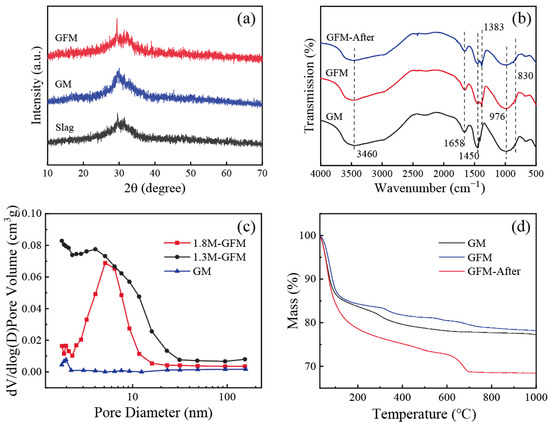
Figure 6.
(a) XRD patterns of slag, GM, and GFM; (b) FTIR spectra of GM, GFM, and GFM-After; (c) Mesopore pore size distribution of GM, 1.3M-GFM, and 1.8M-GFM; (d) TG curves of GM, GFM, and GFM-After.
Figure 6c shows the mesopore pore size distributions of GM as well as 1.3M-GFM and 1.8M-GFM prepared under the same optimal conditions illustrated above (H2O2 = 1 mL, membrane thickness = 6.5 mm). It is noticeable that the pore size of the membrane after foaming was much larger than before, and the 1.8M-GFM nanopores were concentrated around 5 nm. The pore size of the 1.3M-GFM was larger than 1.8M-GFM, which is in accordance with the previous results of the distribution of pore sizes of the macropores and flux. The comparison of their BET surface area and pore volume is listed in Table 2. The BET surface area of 68.74 m2/g for 1.8M-GFM was far larger than that of 20.41 m2/g for 1.3 M-GFM, which can be well explained by the fact that the dye removal efficiency of 1.8M-GFM is not inferior or even better with a flux smaller than 1.3 M-GFM because it has a larger surface area and provides more reaction sites.
Table 2.
Comparison of BET surface area for GM, 1.3M-GFM, and 1.8M-GFM.
Figure 6d displays the TG curves of GM, GFM, and GFM-After. It indicates the mass loss of the samples with a function of temperature. It is evident that GFM had lower mass loss and was more thermally stable. The weight loss of the sample was concentrated below 200 °C, and the change was not visible after 300 °C. In particular, the fastest weight loss rate of GM was at 100 °C, mainly due to the evaporation of free water. The mass loss of GFM-After reached 31.6%, and there was a peak at 700 °C. This mass loss may have resulted from the creation of additional carbonates following the interaction of the geopolymer with water. Therefore, GFM still had good stability when treating dye wastewater at high temperatures.
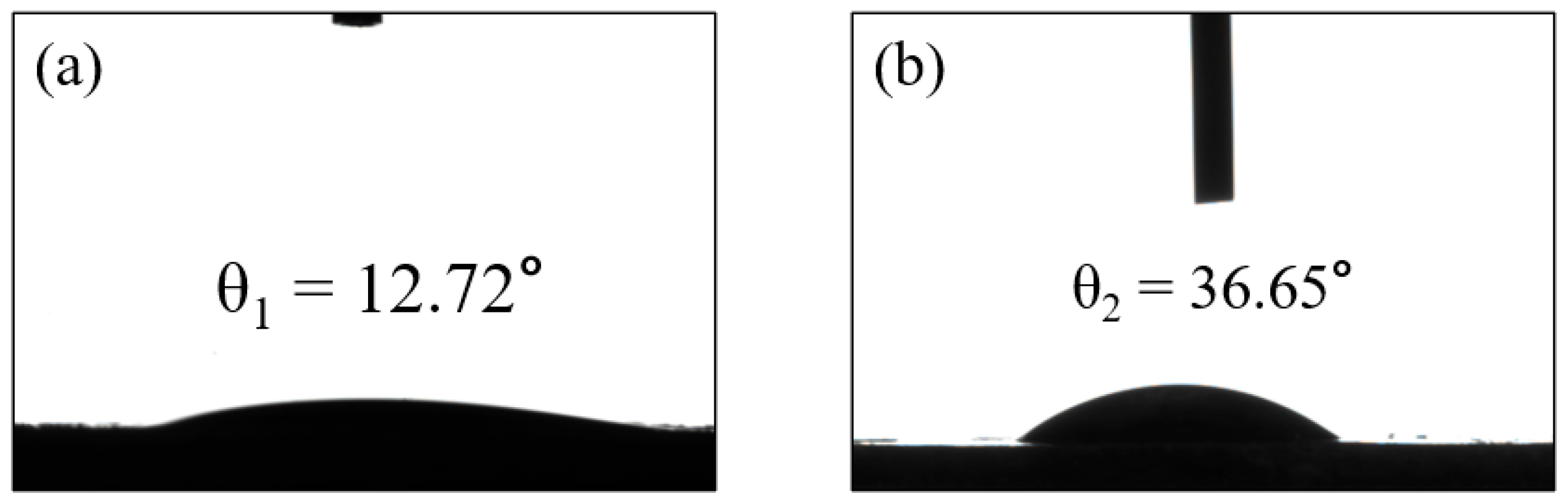
A common technique for determining the hydrophobicity/hydrophilicity of a membrane is to measure the water contact angle. If θ is less than 90°, some of the surface is hydrophilic, and the smaller the contact angle, the better the hydrophilicity, indicating that the water diffuses faster over the surface. Figure 7a,b shows the measurements of the static water contact angle of GM and GFM, which are 12.72° ± 0.5° and 36.65° ± 0.5°, respectively. From the results of the water contact angle, it is clear that the geopolymer is very hydrophilic, and the water contact angle of the GFM slightly increased. The porosity of the membrane is also one of the key conditions for evaluating the membrane performance. The bulk density of the GFM was 0.8533, the true density was 2.02, which was found using the specific gravity bottle method, and the porosity was calculated to be 58%, which is high enough to allow water to penetrate the surface more easily to promote wetting, satisfying its good mechanical stability properties. The performance characteristics of GFM described above all support the hydrophilic nature, which is advantageous in all water treatment-related applications, as it promotes efficient water transport and contributes to the overall performance and durability of the membrane [35]. Performance comparisons with other substrate membranes are listed in Table 3; compared to other catalytic membranes, GFM shows high flux and efficient dye removal.
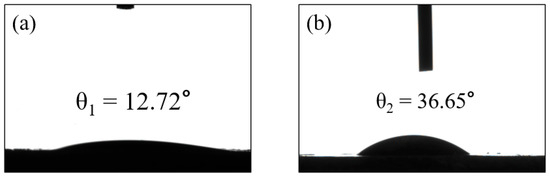
Figure 7.
The water contact angles of (a) GM and (b) GFM.
Table 3.
Comparison of the characteristics and performances of different carrier membranes.
3.4. The Mechanism of Dye Removal by GFM
We found that, when GFM and H2O2 exist alone, they can barely affect the degradation of dyes, while in the GFM/H2O2 reaction system, the removal efficiency improved significantly. The removal efficiency of CV was up to 100% in 5 min. The above results fully demonstrate that the reaction occurred after H2O2 passed through the hollow tube and had contact with GFM, and it relied on the sufficiently large flux diffusion to act on the pollutants, not through physical retention but through Fenton-like oxidation, to remove dyes. In this event, hydroxyl radicals are the main active substances.
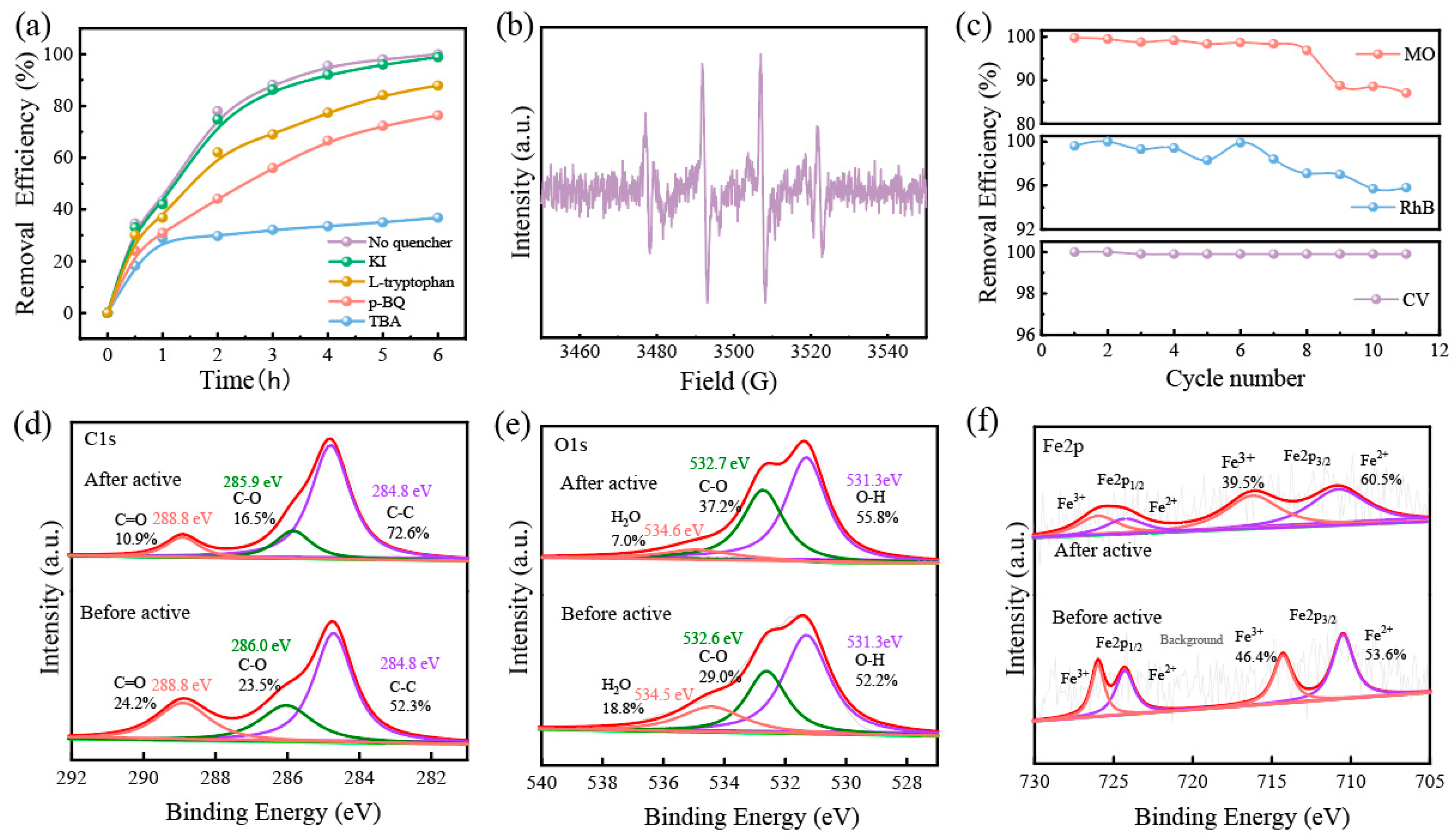
In order to further analyze the degradation mechanism, we used Rhodamine B for quenching experiments; TBA, KI, p-BQ, and L-histidine as ·OH, ·OHsurf, ·O2−, and 1O2 bursting agents, respectively [42]; as well as a blank group for control experiments (50 mg/L, 200 mL, pH = 7). The results are shown in Figure 8a. There was no discernible difference in the removal efficiency of Rh B after KI and L-histidine were added, which could indicate that little leached iron was homogeneously catalyzed with H2O2 in the solution. Nevertheless, the removal efficiency of Rh B dropped by nearly 60% after the addition of hydroxyl radical bursting agent TBA, and these findings conclude that ·OH was the main active substance for degrading dyes. The free radicals generated in the GFM/H2O2 system were detected by EPR (in Figure 8b). A distinct characteristic peak ratio of 1:2:2:1 quadratic signal corresponding to ·OH was detected, confirming that GFM/H2O2 can catalyze the production of ·OH reactive substances from H2O2 for the effective removal of dye wastewater.
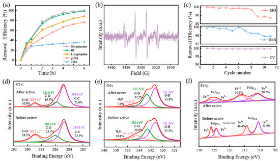
Figure 8.
(a) removal efficiency of RhB with different free radical scavengers; (b) EPR; (c) cyclic degradation tests of GFM; the XPS spectra of (d) C 1s, (e) O 1s, and (f) Fe 2p of GFM and GFM-After.
To assess the stability of GFM, a cycling test was performed for dye removal. As shown in Figure 8c, among them, the removal efficiency of MO decreased to 87.6% at the eighth cycle, which might be related to the attenuation of membrane flux and the depletion of iron ions. In general, GFM was able to maintain more than a 90% degradation efficiency after 11 cycles in the three dye wastewaters, which is strong evidence that the GFM is capable of good stability for long-term wastewater treatment.
The XPS analysis of GFM and GFM-After was performed to understand the changes before and after the reaction and to study the mechanism. The atomic percentages of GFM and GFM-After determined by XPS are listed in Table 4. The binding energies of C1s in Figure 8d are 284.8 eV, 285.9 eV, and 288.8 eV, which are attributed to the C-C, C-O-H, and C=O peaks, respectively [43]. In the C1s spectra, the bound form of carbon was enriched. This may be attributed to the presence of organic substances, such as sodium dodecyl sulfate, and the reaction of the sodium salt with atmospheric CO2 to form carbonates [31]. The binding energies of O1s in Figure 8e are 531.3 eV, 532.6 eV, and 534.5 eV, and they can be ascribed to defective oxides and metal hydroxides (-OH), C-O, and adsorbed water (H2O), respectively. There was a certain shift in the binding energies of O1s with a slight increase after the reaction, probably as a result of the redox reaction of the electron transfer in the Fenton-like process [44]. The XPS spectra of Fe2p are shown in Figure 8f. Fe2p3/2 and Fe2p1/2 are the two major asymmetric peaks located at 712.5 eV and 725.2 eV, respectively. The Fe2p3/2 peak (716.1 eV) and Fe2p1/2 peak (725.9 eV) are attributed to Fe3+, and the binding energies of Fe2+ were 710.5 eV (Fe2p3/2) and 724.3 eV (Fe2p1/2), respectively. This indicates that the loaded iron exists in +2 and +3 valence states [45]. In the Fenton-like system, the oxidation of Fe2+ to Fe3+ led to a decrease in the Fe2+peak area and a decrease in the relative content; yet, as can be seen from the figure, the relative content of Fe(II) after the reaction increased instead of decreasing (53.6% to 60.5%). The relative content of Fe(II) after the reaction increased instead of decreasing (53.6% to 60.5%); moreover, the iron ions were consumed while the relative content of metal hydroxide (-OH) increased, which may be related to the formation of FeO(OH) [46], thereby permitting the redox cycling of Fe (III) ↔ Fe (II), which facilitated hydroxyl radical generation [47]. More specifically, the Fe3+/Fe2+ interconversion resulted in the continuous reduction of Fe3+ to a dynamic equilibrium with Fe2+, becoming an effective driving force for the production of ·OH, which in turn attacked the structure of the pollutant for degradation. This ensures that the GFM has excellent recyclability.
Table 4.
Atomic percentages of GFM and GFM-After determined by XPS.
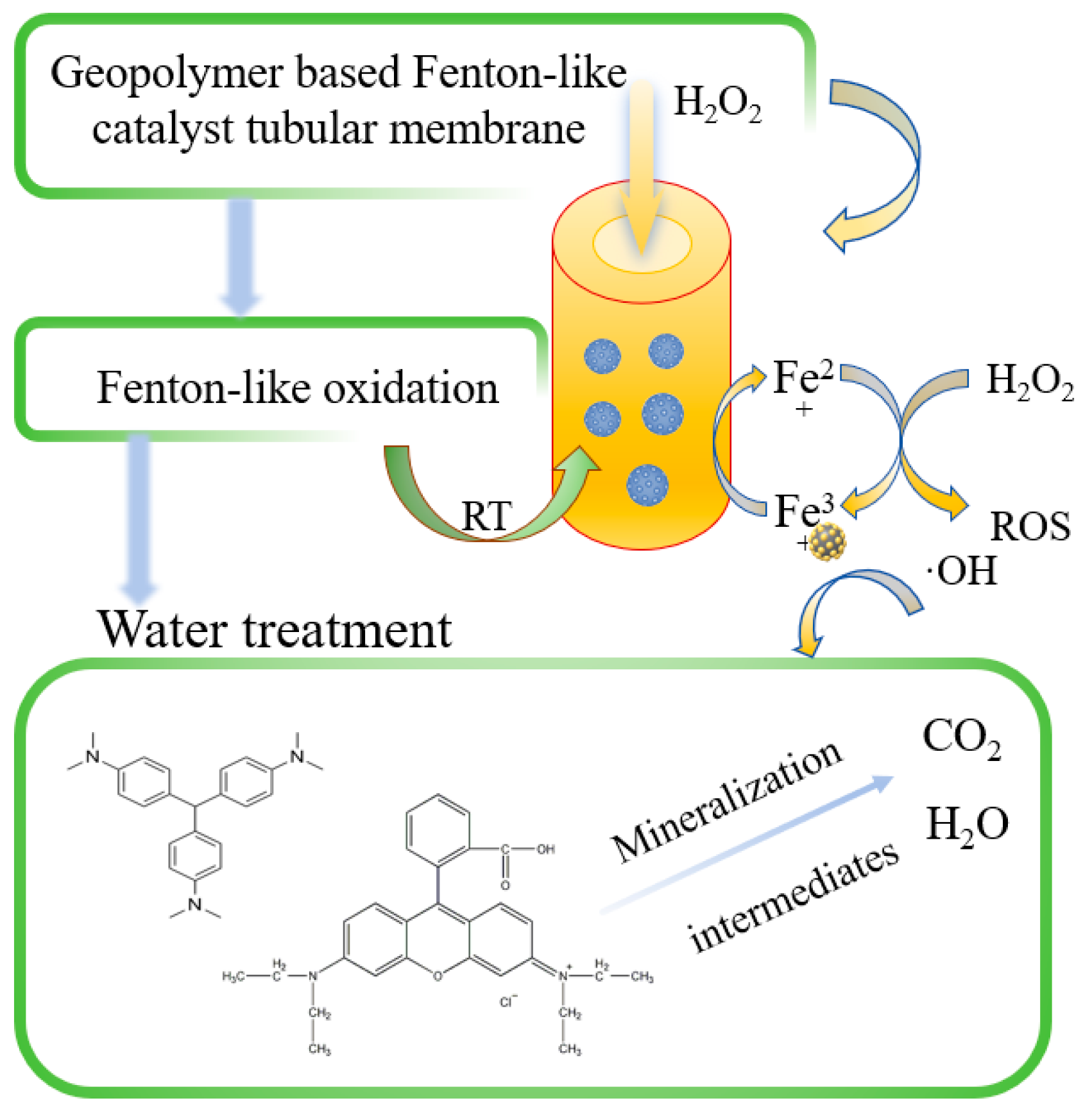
The reaction process of the GFM/H2O2-like Fenton system in Figure 9 was divided into several steps. First, once H2O2 was passed into the system, it immediately contacted with and diffused the GFM, which can provide higher accessibility to the catalyst active sites. Then, ·OH was generated to attack the central carbon atom of the dye molecule, which was degraded by N-demethylation [48]. The benzene ring structure was destroyed, and the chromophore disappeared. The GFM had a porous structure and large enough flux to make the mass transfer process more rapid and effective so that the pollutants were degraded into intermediates while diffusing rapidly from the solid–liquid interface into the solution and then further oxidized and finally degraded into inorganic compounds, such as CO2 and H2O. The combination of the Fenton-like catalyst and membrane can reduce the mass transfer path of ROS, and in the long run, the Fenton-like catalytic membrane eliminated the clogging problem caused by membrane contamination and improved the catalytic performance and the reuse rate of the single-membrane treatment. The membrane matrix of the Fenton-like catalytic membrane can filter and intercept the other pollutants with larger particle sizes, and it ensures that the membrane has enough flux, thus making the catalytic performance more efficient and feasible.
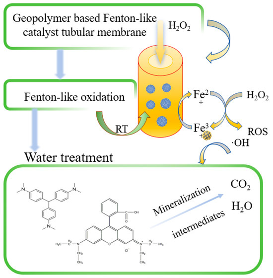
Figure 9.
Mechanism of GFM/H2O2 Fenton-like systems.
4. Conclusions
This work demonstrates the feasibility of coupling membrane separation with Fenton-like technology by investigating the use of a simple direct foaming method with inexpensive, environmentally friendly, and readily available raw materials for the preparation of a geopolymer-based Fenton-like catalytic tubular membrane loaded with iron ions.
This process can be adapted to obtain tubular membranes with different fluxes by adjusting the foaming parameters and formulations, and we used it for dye wastewater treatment. The catalytic tubular membrane showed high removal efficiency and excellent stability in dye degradation tests. A detailed characterization of its chemical composition, macro-microstructure, and porosity was also carried out. These preliminary results indicate that the GFM and its membrane devices have a promising potential for water treatment. Taking into account the limited scope of the study, further research could be conducted to evaluate the performance of the material for other pollutants in aqueous media and in complex environments (e.g., mixed dyes, inorganic salt ions, etc.).
The tubular membrane solves the problems of membrane susceptibility to fouling, poor recycling performance and iron sludge formation in the Fenton process, harsh reaction conditions, and, due to the characteristics of the tubular membrane, the consumption of hydrogen peroxide, which is costly to store can be reduced, thus expanding the potential for industrial value production.
Author Contributions
Conceptualization and writing—original draft, P.X.; Formal analysis and Funding acquisition, X.C.; Investigation, K.C.; Writing—review & editing, X.D.; Validation, Q.Y. All authors have read and agreed to the published version of the manuscript.
Funding
This research was funded by the Chinese Natural Science Fund (No. 51772055) and the Guangxi Natural Science Fund (No. 2022GXNSFDA035062).
Data Availability Statement
Data are available on request.
Conflicts of Interest
The authors declare no conflict of interest.
References
- Solayman, H.M.; Hossen, M.A.; Abd Aziz, A.; Yahya, N.Y.; Leong, K.H.; Sim, L.C.; Monir, M.U.; Zoh, K.-D. Performance evaluation of dye wastewater treatment technologies: A review. J. Environ. Chem. Eng. 2023, 11, 109610. [Google Scholar] [CrossRef]
- Slama, H.B.; Chenari Bouket, A.; Pourhassan, Z.; Alenezi, F.N.; Silini, A.; Cherif-Silini, H.; Oszako, T.; Luptakova, L.; Golińska, P.; Belbahri, L. Diversity of Synthetic Dyes from Textile Industries, Discharge Impacts and Treatment Methods. Appl. Sci. 2021, 11, 6255. [Google Scholar] [CrossRef]
- Rasero, C.R.; Jimenez, V.M.; Franco, M.F.A.; González, C.F.; Tercero, J.P.; Correa, E.M.C. Use of Zero-Valent Iron Nanoparticles (nZVIs) from Environmentally Friendly Synthesis for the Removal of Dyes from Water—A Review. Water 2024, 16, 1607. [Google Scholar] [CrossRef]
- Nguyen, T.H.; Nguyen, D.V.; Hatamoto, M.; Takimoto, Y.; Watari, T.; Do, K.-U.; Yamaguchi, T. Harnessing iron materials for enhanced decolorization of azo dye wastewater: A comprehensive review. Environ. Res. 2024, 258, 119418. [Google Scholar] [CrossRef] [PubMed]
- Artifon, W.; Mazur, L.P.; de Souza, A.A.U.; de Oliveira, D. Production of bioflocculants from spent brewer’s yeast and its application in the treatment of effluents with textile dyes. J. Water Process Eng. 2022, 49, 102997. [Google Scholar] [CrossRef]
- Cao, Y.; Yang, L.; Liu, F.; Yu, Q. Adsorption experiments and mechanisms of methylene blue on activated carbon from garden waste via deep eutectic solvents coupling KOH activation. Biomass Bioenergy 2024, 182, 107074. [Google Scholar] [CrossRef]
- Wang, Y.-Q.; Ding, J.; Pang, J.-W.; Wu, C.-D.; Sun, H.-J.; Fang, R.; Ren, N.-Q.; Yang, S.-S. Promotion of anaerobic biodegradation of azo dye RR2 by different biowaste-derived biochars: Characteristics and mechanism study by machine learning. Bioresour. Technol. 2024, 396, 130383. [Google Scholar] [CrossRef]
- Nawaz, H.; Umar, M.; Nawaz, I.; Ullah, A.; Tauseef Khawar, M.; Nikiel, M.; Razzaq, H.; Siddiq, M.; Liu, X. Hybrid PVDF/PANI Membrane for Removal of Dyes from Textile Wastewater. Adv. Eng. Mater. 2022, 24, 2100719. [Google Scholar] [CrossRef]
- Patel, R.P.; Pataniya, P.M.; Siraj, S.; Sahatiya, P.; Sumesh, C.K. Simultaneous production of green hydrogen and decontamination of dye wastewater using WSe2–CuO/graphite electrochemical cell. Int. J. Hydrogen Energy 2024, 55, 815–827. [Google Scholar] [CrossRef]
- Cheng, Z.; Luo, S.; Li, X.; Zhang, S.; Thang Nguyen, T.; Guo, M.; Gao, X. Ultrasound-assisted heterogeneous Fenton-like process for methylene blue removal using magnetic MnFe2O4/biochar nanocomposite. Appl. Surf. Sci. 2021, 566, 150654. [Google Scholar] [CrossRef]
- Adane, T.; Adugna, A.T.; Alemayehu, E. Textile Industry Effluent Treatment Techniques. J. Chem. 2021, 2021, 5314404. [Google Scholar] [CrossRef]
- AlHadithy, Z.E.; AbdulRazak, A.A.; Al-Ghaban, A.M.H.A.; Alsalhy, Q.F.; Meskher, H.; Al-Juboori, R.A.; Katibi, K.K.; Lawal, D.U. Advancements in Water Treatment with MXene-Enhanced Membranes: A Review of Current Progress and Future Directions. Water Air Soil Pollut. 2024, 235, 809. [Google Scholar] [CrossRef]
- Grylewicz, A.; Mozia, S. Polymeric mixed-matrix membranes modified with halloysite nanotubes for water and wastewater treatment: A review. Sep. Purif. Technol. 2021, 256, 117827. [Google Scholar] [CrossRef]
- Nthunya, L.N.; Chong, K.C.; Lai, S.O.; Lau, W.J.; Maldonado, E.A.L.; Camacho, L.M.; Shirazi, M.M.A.; Ali, A.; Mamba, B.B.; Osial, M.; et al. Progress in membrane distillation processes for dye wastewater treatment: A review. Chemosphere 2024, 360, 142347. [Google Scholar] [CrossRef]
- Shaffer, D.L.; Werber, J.R.; Jaramillo, H.; Lin, S.; Elimelech, M. Forward osmosis: Where are we now? Desalination 2015, 356, 271–284. [Google Scholar] [CrossRef]
- Tanveer, R.; Yasar, A.; Nizami, A.-S.; Tabinda, A.B. Integration of physical and advanced oxidation processes for treatment and reuse of textile dye-bath effluents with minimum area footprint. J. Clean. Prod. 2023, 383, 135366. [Google Scholar] [CrossRef]
- Huddersman, K.; Ekpruke, A.; Asuelimen, L. Application of AOPs in the treatment of OSPAR chemicals and a comparative cost analysis. Crit. Rev. Environ. Sci. Technol. 2019, 49, 277–317. [Google Scholar] [CrossRef]
- Xavier, S.; Gandhimathi, R.; Nidheesh, P.V.; Ramesh, S.T. Comparison of homogeneous and heterogeneous Fenton processes for the removal of reactive dye Magenta MB from aqueous solution. Desalination Water Treat. 2015, 53, 109–118. [Google Scholar] [CrossRef]
- Saleh, R.; Taufik, A. Degradation of methylene blue and congo-red dyes using Fenton, photo-Fenton, sono-Fenton, and sonophoto-Fenton methods in the presence of iron(II,III) oxide/zinc oxide/graphene (Fe3O4/ZnO/graphene) composites. Sep. Purif. Technol. 2019, 210, 563–573. [Google Scholar] [CrossRef]
- Xu, N.; Han, J.; Feng, Y.; Xiao, C. Polyacrylonitrile/poly(acrylic acid) layer-by-layer superimposed composite nanofiber membrane with low iron ion leaching-out and stable methylene blue-removing performance. J. Membr. Sci. 2022, 641, 119935. [Google Scholar] [CrossRef]
- Chen, B.; Hu, X.; Wang, J.; Li, R.; Shen, L.; Xu, Y.; Zhang, M.; Hong, H.; Lin, H. Novel catalytic self-cleaning membrane with peroxymonosulfate activation for dual-function wastewater purification: Performance and mechanism. J. Clean. Prod. 2022, 355, 131858. [Google Scholar] [CrossRef]
- Nurlina, N.; Pratama, J.H.; Pambudi, A.B.; Rahmawati, Z.; Subaer, S.; Abdullah, M.M.A.B.; Gusrizal, G.; Fansuri, H. A review of geopolymer membrane for water treatment. Appl. Clay Sci. 2024, 251, 107301. [Google Scholar] [CrossRef]
- Ji, Z.; Zhang, G.; Liu, R.; Qu, J.; Liu, H. Potential applications of solid waste-based geopolymer materials: In wastewater treatment and greenhouse gas emission reduction. J. Clean. Prod. 2024, 443, 141144. [Google Scholar] [CrossRef]
- Ji, Z.; Pei, Y. Bibliographic and visualized analysis of geopolymer research and its application in heavy metal immobilization: A review. J. Environ. Manag. 2019, 231, 256–267. [Google Scholar] [CrossRef]
- Huang, J.; Li, Z.; Zhang, J.; Zhang, Y.; Ge, Y.; Cui, X. In-situ synchronous carbonation and self-activation of biochar/geopolymer composite membrane: Enhanced catalyst for oxidative degradation of tetracycline in water. Chem. Eng. J. 2020, 397, 125528. [Google Scholar] [CrossRef]
- He, P.; Zhang, F.; Zhang, Y.; Chen, H. Multifunctional fly ash-based GO/geopolymer composite membrane for efficient oil-water separation and dye degradation. Ceram. Int. 2023, 49, 1855–1864. [Google Scholar] [CrossRef]
- Liu, L.; Deng, X.; He, Y.; Cui, X.-M. Synthesis of composite zeolite membrane by low-temperature water bath for efficient dynamic hardwater softening. J. Environ. Chem. Eng. 2023, 11, 109482. [Google Scholar] [CrossRef]
- Masi, G.; Rickard, W.D.A.; Vickers, L.; Bignozzi, M.C.; van Riessen, A. A comparison between different foaming methods for the synthesis of light weight geopolymers. Ceram. Int. 2014, 40, 13891–13902. [Google Scholar] [CrossRef]
- Xu, M.-X.; He, Y.; Liu, Z.-H.; Tong, Z.-F.; Cui, X.-M. Preparation of geopolymer inorganic membrane and purification of pulp-papermaking green liquor. Appl. Clay Sci. 2019, 168, 269–275. [Google Scholar] [CrossRef]
- Papa, E.; Medri, V.; Landi, E. Geopolymer-hydroxyapatite composite foams for wastewater remediation. Ceram. Int. 2024, 50, 50377–50387. [Google Scholar] [CrossRef]
- Zhang, Z.; Yu, H.; Xu, M.; Cui, X. Preparation, characterization and application of geopolymer-based tubular inorganic membrane. Appl. Clay Sci. 2021, 203, 106001. [Google Scholar] [CrossRef]
- Chen, C.; Xu, M.-x.; Deng, X.; He, Y.; Cui, X. Preparation of metakaolin-based geopolymer membrane and its application in black liquor treatment. Appl. Clay Sci. 2023, 232, 106773. [Google Scholar] [CrossRef]
- Zhao, B.; Deng, X.; He, Y.; Xiao, P.; Dhmees, A.S.; Cui, X. Carbonic anhydrase immobilized on Zn(II)-geopolymer membrane for CO2 capture. Biochem. Eng. J. 2024, 208, 109364. [Google Scholar] [CrossRef]
- Lv, X.; Qin, Y.; Liang, H.; Cui, X. Effects of modifying agent on rheology and workability of alkali-activated slag paste for 3D extrusion forming. Constr. Build. Mater. 2021, 302, 124062. [Google Scholar] [CrossRef]
- Al-Sammarraie, E.S.A.; Sabirova, T.M.; Meskher, H.; Al-Juboori, R.A.; Zyryanov, G.V.; Alsalhy, Q.F. Nanocomposite UF membrane of PVC/nano-silica modified with SDS for carwash wastewater treatment. Environ. Sci. Adv. 2025, 4, 469–488. [Google Scholar] [CrossRef]
- Zhang, G.; Lu, L.; Wang, H.; Lin, H.; Li, J.; Yan, Y.; Cui, J.; Jiang, J. Bio-Inspired Underwater Superoleophobic Aramid Nanofiber-Based Aerogel Membranes for Highly Efficient Removal of Emulsified Oils and Organic Dyes. Langmuir 2024, 40, 13995–14006. [Google Scholar] [CrossRef]
- Wang, Y.; Liu, Z.; Wei, X.; Liu, K.; Wang, J.; Hu, J.; Lin, J. An integrated strategy for achieving oil-in-water separation, removal, and anti-oil/dye/bacteria-fouling. Chem. Eng. J. 2021, 413, 127493. [Google Scholar] [CrossRef]
- Zhang, G.; Li, Y.; Gao, A.; Zhang, Q.; Cui, J.; Zhao, S.; Zhan, X.; Yan, Y. Bio-inspired underwater superoleophobic PVDF membranes for highly-efficient simultaneous removal of insoluble emulsified oils and soluble anionic dyes. Chem. Eng. J. 2019, 369, 576–587. [Google Scholar] [CrossRef]
- Mansor, E.S.; Ali, H.; Abdel-Karim, A. Efficient and reusable polyethylene oxide/polyaniline composite membrane for dye adsorption and filtration. Colloid Interface Sci. Commun. 2020, 39, 100314. [Google Scholar] [CrossRef]
- Ding, C.; Zhang, M.; Lyu, B.; Guo, Z.; Xing, N.; Pang, X.; Wu, T.; Jiang, Y.; Zhang, R.; El-Gendi, A.; et al. Micropore engineering of polyamide loose nanofiltration membrane for efficient dye/salt separation. J. Membr. Sci. 2024, 705, 122932. [Google Scholar] [CrossRef]
- Alani, H.A.; Alsalhy, Q.F.; Al-Saadi, S.; Alani, F.H.; Meskher, H.; Al-Juboori, R.A.; Russo, F.; Chiappetta, G.; Di Luca, G.; Figoli, A. Terephthalic-co-glycerol-g-fumaric Acid: A Promising Nanopolymer for Enhancing PPSU Membrane Properties. ChemEngineering 2025, 9, 12. [Google Scholar] [CrossRef]
- Shen, Y.; Xiao, Y.; Zhang, H.; Fan, H.; Li, Y.; Yan, Z.; Zhang, W.-H. Synthesis of magnetic biochar-supported Fe-Cu bimetallic catalyst from pulp and paper mill wastes for the Fenton-like removal of rhodamine B dye. Chem. Eng. J. 2023, 477, 146823. [Google Scholar] [CrossRef]
- Xu, X.; Li, H.; Zhang, Q.; Hu, H.; Zhao, Z.; Li, J.; Li, J.; Qiao, Y.; Gogotsi, Y. Self-Sensing, Ultralight, and Conductive 3D Graphene/Iron Oxide Aerogel Elastomer Deformable in a Magnetic Field. ACS Nano 2015, 9, 3969–3977. [Google Scholar] [CrossRef] [PubMed]
- Yao, Y.; Chen, H.; Qin, J.; Wu, G.; Lian, C.; Zhang, J.; Wang, S. Iron encapsulated in boron and nitrogen codoped carbon nanotubes as synergistic catalysts for Fenton-like reaction. Water Res. 2016, 101, 281–291. [Google Scholar] [CrossRef]
- Wang, L.; Zhou, C.; Yuan, Y.; Jin, Y.; Liu, Y.; Jiang, Z.; Li, X.; Dai, J.; Zhang, Y.; Siyal, A.A.; et al. Catalytic degradation of crystal violet and methyl orange in heterogeneous Fenton-like processes. Chemosphere 2023, 344, 140406. [Google Scholar] [CrossRef]
- Samir, B.; Bakhta, S.; Bouazizi, N.; Sadaoui, Z.; Allalou, O.; Le Derf, F.; Vieillard, J. TBO Degradation by Heterogeneous Fenton-like Reaction Using Fe Supported over Activated Carbon. Catalysts 2021, 11, 1456. [Google Scholar] [CrossRef]
- Mateus, L.; Moreno-Castilla, C.; López-Ramón, M.V.; Cortés, F.B.; Álvarez, M.Á.; Medina, O.E.; Franco, C.A.; Yebra-Rodríguez, Á. Physicochemical characteristics of calcined MnFe2O4 solid nanospheres and their catalytic activity to oxidize para-nitrophenol with peroxymonosulfate and n-C7 asphaltenes with air. J. Environ. Manag. 2021, 281, 111871. [Google Scholar] [CrossRef]
- Guo, S.; Yang, Z.; Zhang, H.; Yang, W.; Li, J.; Zhou, K. Enhanced photocatalytic degradation of organic contaminants over CaFe2O4 under visible LED light irradiation mediated by peroxymonosulfate. J. Mater. Sci. Technol. 2021, 62, 34–43. [Google Scholar] [CrossRef]


Disclaimer/Publisher’s Note: The statements, opinions and data contained in all publications are solely those of the individual author(s) and contributor(s) and not of MDPI and/or the editor(s). MDPI and/or the editor(s) disclaim responsibility for any injury to people or property resulting from any ideas, methods, instructions or products referred to in the content. |
© 2025 by the authors. Licensee MDPI, Basel, Switzerland. This article is an open access article distributed under the terms and conditions of the Creative Commons Attribution (CC BY) license (https://creativecommons.org/licenses/by/4.0/).