Article

Titanium Meets Carbon: Enhanced Reusable Filters for Oil–Water Separation and Environmental Remediation

by
Amir-Hadi Boroumand
1,
Kayla Laguana
1,
Eric Dudley
1,
Pilar Cuadros-Arias
1,
Adrian Rubio
1,
Zachary Shin
1,
Jack Webster
2 and
Mingheng Li
1,*
1
Department of Chemical and Materials Engineering, California State Polytechnic University, Pomona, CA 91768, USA
2
Department of Materials Science and Engineering, University of California, Irvine, CA 92697, USA
*
Author to whom correspondence should be addressed.
Separations 2025, 12(4), 83; https://doi.org/10.3390/separations12040083
Submission received: 6 March 2025 / Revised: 27 March 2025 / Accepted: 27 March 2025 / Published: 30 March 2025

Abstract

:
To mitigate the environmental effects of oil spills, a novel hydrophilic–oleophobic mixed-coated filter was developed for efficient oil–water separation and surface oil recovery. The coating consisted of titanium dioxide nanoparticles (TiO2) and ultra-fine carbon black powder, deposited onto a 304 stainless-steel mesh substrate via spray deposition, followed by high-temperature sintering. This process induced a phase transition in TiO2 from anatase to rutile, and formed a TiC khamrabaevite. The filter’s performance was evaluated using contact angle measurements and filtration tests with a motor oil–water mixture, while SEM, EDS, and XRD analyses characterized its morphology and coating structure. Contact angle testing confirmed that carbon modification significantly enhanced the oleophobicity of the TiO2 filter, and SEM imaging demonstrated higher substrate coating adhesion, enabling multiple reuse cycles. These findings highlight the potential of TiO2 carbon composite coatings in improving oil spill remediation technologies by offering a reusable and efficient filtration system.

1. Introduction

From 1970 to 2023, 1864 accidental oil spills occurred, and approximately 4.5 billion gallons of oil were discharged from tankers globally [1]. The long-term consequences of oil pollution are devastating, leading to decreased biodiversity, habitat destruction, and overall poor wildlife health of marine ecosystems [2]. Additionally, oil spills impose significant financial burdens, such as cleanup costs, loss of recreational revenue, and economic disruptions for local businesses and industries [3]. In 2023 alone, the U.S. government spent USD 92 million to restore waterways and communities affected by oil spills [4]. One of the largest spills in history is the 2010 Deepwater Horizon Spill. Approximately 210 million gallons of oil spilled into the Gulf of Mexico, resulting in severe habitat degradation and economic losses of USD 17 billion [5]. Although there are efforts to transition to renewable energy, the global dependence on oil remains high and continues to rise, increasing the risk of future spills [6]. The long-lasting consequences of oil spills highlight the need for effective prevention and response strategies.
Contemporary solutions to address these environmental concerns are limited in terms of effectiveness and practicality. Current oil cleanup methods include absorption, dispersion, skimming, in situ burning, and bioremediation. Absorption involves using absorbent materials to soak up and retain spilled surface oil. These “sorbent materials” selectively absorb oil, effectively removing it from water [7,8]. Though viable, each sorbent is designed for specific oil spill conditions, which limits its flexibility and availability to help in unpredictable environments like harsh ocean climates. Furthermore, the addition of sorbent materials adds excessive amounts of mass to the spill and creates oil-soaked waste [8,9]. Dispersion employs spraying chemicals on the top layer of oil spills, decomposing oil into finer particles. These added chemicals also increase water toxicity and are harmful to nearby marine life [10,11]. Skimming involves collecting oil off the surface of the water, either through suction or adhesion methods. For example, vacuum skimmers use hoses to suck an oil–water mixture off the surface of spill areas, or oil-attracting ropes cause oil adherence for cleanup. However, this method has been cited to demonstrate poor oil recovery [11,12]. In situ burning requires burning the surface layer of oil spills. This process leaves behind heavy oil residue and produces black smoke and poly-aromatic hydrocarbons (PAHs), impacting aquatic ecosystems and air quality [13,14]. Bioremediation introduces microorganisms to the spill environment. These microorganisms use oil as an energy source for effective oil degradation. Compared to the methods discussed, bioremediation offers a more environmentally friendly solution. However, it is a slow process, and its effectiveness depends on the conditions of the spill environment [15].
To address the drawbacks of current methods, this study focused on improving a more recent solution: oleophobic and hydrophilic coatings for efficient oil–water separation. This method allows clean water to pass through coated filters, while oil is retained and captured for reuse. Studies of oleophobic and hydrophilic surface treatments date to 2000, where a difference between the hexadecane contact angle and the water contact angle for titanium dioxide (TiO2) thin film surfaces was discovered [16]. Since then, more research has been completed to further support the potential of TiO2 coatings in oil–water separation. Ross et al. [17] proposed a hydrophilic–oleophobic coating derived from a titanium (IV) isopropoxide precursor to TiO2. This study also determined the most optimal bonding technique to adhere TiO2 onto paper- and cotton-based substrates. Subsequently, Sico et al. [18] studied the potential of TiO2 nanopowder coatings on varying aperture sizes of 304 stainless steel mesh substrates. Although promising, both solutions exhibited a decline in oil–water separation ability after repeated use, rendering them unreliable for large-scale applications.
This study proposes a novel approach to oil–water separation by developing a mixed coating of carbon black and TiO2 nanopowder on a 304 stainless steel mesh. Previous research has shown that carbon black enhances the photocatalytic activity of TiO2, improving its ability to degrade organic pollutants. These studies used a sol-gel method to deposit the TiO2 precursors onto the tested films and doped TiO2 with carbon black under visible light [19,20,21,22]. Our study sought to observe the synergistic effect of carbon black and TiO2 in providing more active sights for TiO2–oil interaction, while attempting to conserve the photocatalytic properties of carbon enhancement.
To achieve a strong coating, the coefficient of thermal expansion (CTE) of the substrate and the coating must be considered. An optimal difference between the two CTE’s should be less than 10% to ensure proper adherence and prevent cracking during the sintering process, which can cause the coating to flake off during use and decrease reusability [23]. Studies carried out on the CTE of TiO2 nanoparticles [24] and 304 stainless steel [25,26] show a significant difference between the two values at 425 °C, a temperature close to the sintering temperature for these filters. This indicates a thermal expansion incompatibility between the substrate and the coating, in which the addition of carbon can create an improvement in overall adherence, increasing the reusability of the filters.
To achieve a thin and even coating, a TiO2 was spray-deposited onto the stainless-steel mesh substrate pasted with carbon black, replacing the traditional sol-gel method. Opting for spray deposition over the traditional sol-gel method makes for a more efficient and scalable process. The following groups were tested: TiO2 coating, carbon black coating, and TiO2–carbon composite coating. Each group’s separation efficiency, oleophobicity, hydrophilicity, and reusability were assessed through filtration tests and contact angle measurements. The filters were analyzed via scanning electron microscope (SEM), X-ray diffraction (XRD), and energy-dispersive spectroscopy (EDS) to evaluate the coating’s adhesion, elemental composition, and structural characterization. An effective separation was observed, showing a positive impact on separation and reusability of the filters with the addition of the carbon black to the TiO2 coating.

2. Materials and Methods

2.1. Materials

2.1.1. Substrate Material

The substrate material and aperture size were kept consistent to evaluate the performance of each coating. A 304 stainless steel mesh substrate with an aperture size of 0.18 mm was chosen for its ability to resist corrosion, suitable for marine water applications. The corrosion resistance of stainless steels is dependent on the composition, thickness, and denseness of the materials passive film [27]. It should be noted that other forms of stainless steel such as 316 stainless steels could offer more corrosion resistance at a higher production cost. One study investigated the corrosion resistance of 304 and 316 stainless steels in a marine environment; the results demonstrated higher passivation in 316 samples over 304 [28]. However, for the scope of this study, the corrosion resistance properties of 304 stainless steel will suffice. Another property significant to the filter is the thermal expansion of the stainless steel. Forms of stainless steel with lower CTE would reduce thermal cracking that occurs during the sintering process. The linear CTE of 316 stainless steel has been cited to be 16 ppm/k for the temperature range of 25 °C–700 °C [29], varying from the cited CTE of 304 stainless steel by 5.7% [30]. Although 316 stainless steel offers improved coating–substrate adhesion, its minimal thermal expansion variation and higher cost led to the selection of 304 stainless steel as the substrate.

2.1.2. TiO2 Nanopowder Material

Titanium dioxide nanopowder, obtained from Sigma-Aldrich (St. Louis, MO, USA), was selected for the formulation of the TiO2–carbon composite coating due to its well-established photocatalytic properties [31]. TiO2 is a widely studied heterogeneous binary metal oxide photocatalyst with extensive applications in environmental remediation [32]. Upon exposure to ultraviolet (UV) radiation, it absorbs photons, leading to the generation of electron–hole pairs on its surface. These charge carriers facilitate redox reactions, resulting in the formation of hydroxyl radicals (-OH) and superoxide anions (O2), which exhibit strong oxidative properties [33]. Consequently, the photocatalytic activity of TiO2 enables the degradation of organic pollutants and the inactivation of a broad spectrum of microorganisms, making it a highly effective material for environmental and antimicrobial applications [34,35].

2.1.3. Carbon Black Material

Carbon black powder was chosen for the coating due to its high specific surface area, which can exceed 1000 m2/g. A high specific surface area is crucial as it increases the number of active sites available for interactions [36]. Furthermore, it enhances the bonding capacity of TiO2 to the stainless-steel mesh substrate, creating a more stable and uniform coating that improves its ability to interact with oil. Additionally, the presence of carbon significantly enhances the photocatalytic and hydrophilic properties of the coating. A study concluded that carbon-doped TiO2 films exhibit a shift in the specific wavelength at which light is absorbed from 370 to 410 nm. This red shift resulted in superior visible-light photocatalytic activity and significantly increased oil contact angle under visible-light illumination [37].

2.2. Coated Filter Preparation

A standardized coating procedure was followed to ensure each filter had an even and consistent coating to mitigate inaccurate data. Substrates were first cut into circles with a 3 cm radius, sanitized with isopropyl alcohol, and then rinsed with de-ionized water before the application of its coating. The TiO2-coated filter, depicted in Figure 1A, was prepared by mixing 10 g of nanopowder with 70 mL of pH 3 acetic acid. The mixed solution was then transferred to a commercially available paint sprayer, evenly applying the coating to the substrate. The coated filter was then sintered at 450 °C for 30 min to evaporate the acetic acid. The carbon black filter, depicted in Figure 1B, was constructed in a similar fashion, the filters were first pasted with a thin layer of acetic acid to ensure adhesion of the powder. The carbon powder was then sifted across both sides of the filter and pasted with a sponge brush to ensure even distribution of the carbon across the filter. The carbon filter was then sintered at 450 °C. The composite coating, depicted in Figure 1C, combined both methods, utilizing a pre-sintered carbon-coated filter, and atomizing TiO2 onto the substrate, then sintering at 800 °C for 30 min.

2.3. Performance Testing

2.3.1. Oil Filtration Test

A standardized procedure for a timed gravity filtration test was conducted to quantify each coating separation ability with respect to one another [17,18,38,39]. Then, 20 mL of 5 W-20 motor oil was poured into a separatory funnel. The coated substrate was placed on the porous plate of a Büchner funnel, ensuring that the oil will pass through the funnel into a graduated cylinder. Once prepared, the separatory funnel valve was opened, allowing oil to flow on top of the substrate. The filters are then allowed to gravity-filtrate over time, where the filtrate volume was recorded approximately every second.
The reusability of the oleophobic filters were evaluated by running the filtration test for successive trials on the same filter. The filter was used for a total of 3 trials with 30 min of UV irradiation at 405 nm between each trial. In doing so, the photocatalysis of the TiO2 was elevated, leading to higher levels of self-cleaning highlighted in [40,41,42], mitigating the effect of contaminants on successive filtration trials.

2.3.2. Contact Angle Test

The oleophobicity and hydrophilicity of the coated filter were evaluated using a static contact angle measurement. The static contact angle test was conducted to assess the wettability of the coated substrate when exposed to oil. A droplet of 5 W-20 motor oil was carefully deposited onto the coated surface using a micropipette to ensure consistency in droplet size. A Canon EOS Rebel T5i camera (Tokyo, Japan) was used to capture a high-resolution image of the droplet at the moment of contact with the substrate. The contact angle, defined as the angle formed at the interface between the oil droplet, the solid surface and the surrounding air was then measured using ImageJ software (version 1.54) with the Drop Analysis plugin, as depicted in Figure 2. This measurement provides insight into the surface energy and oil repellency of the coating, where a higher contact angle indicates greater oleophobicity.

3. Results and Discussion

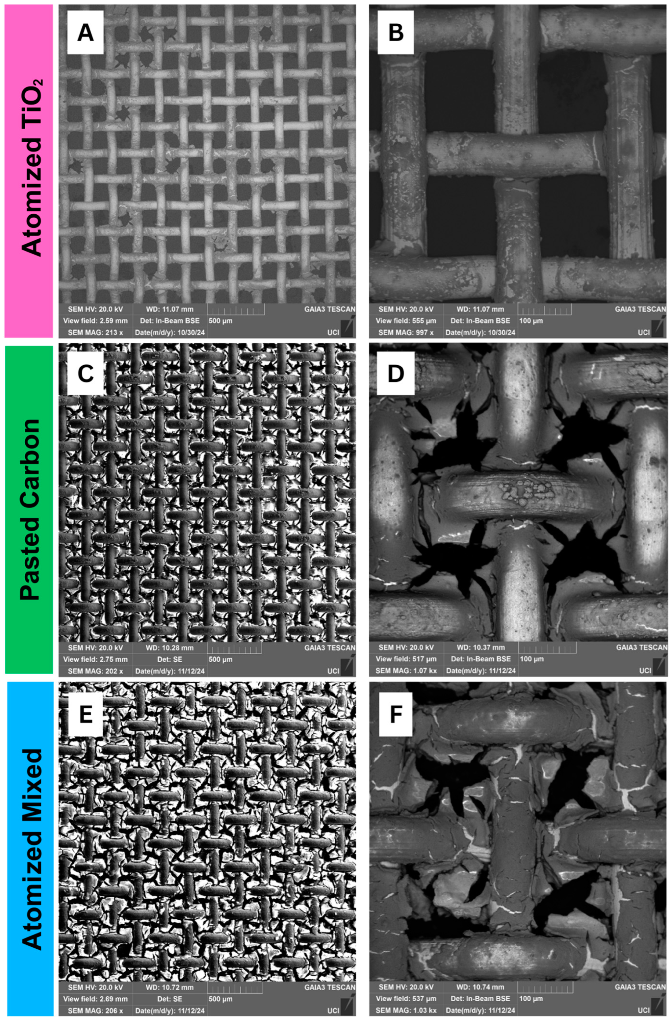
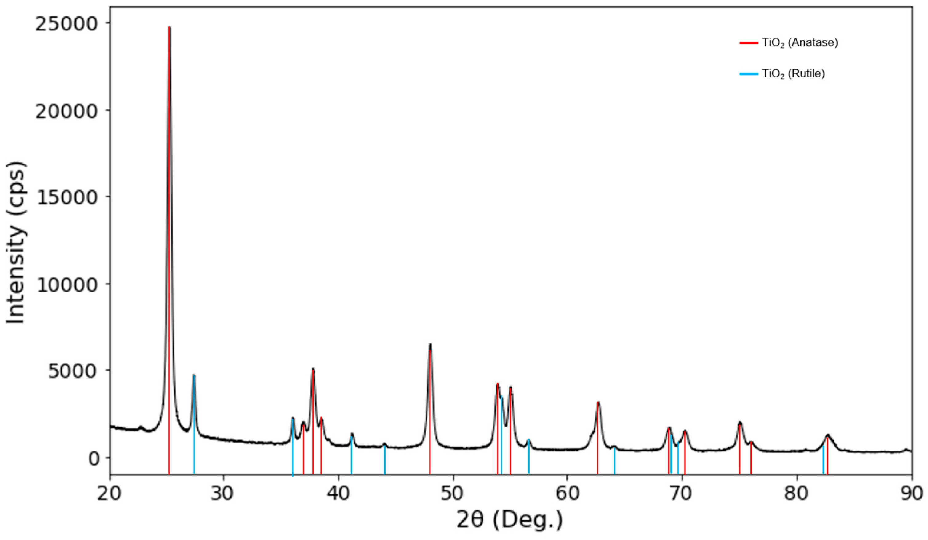
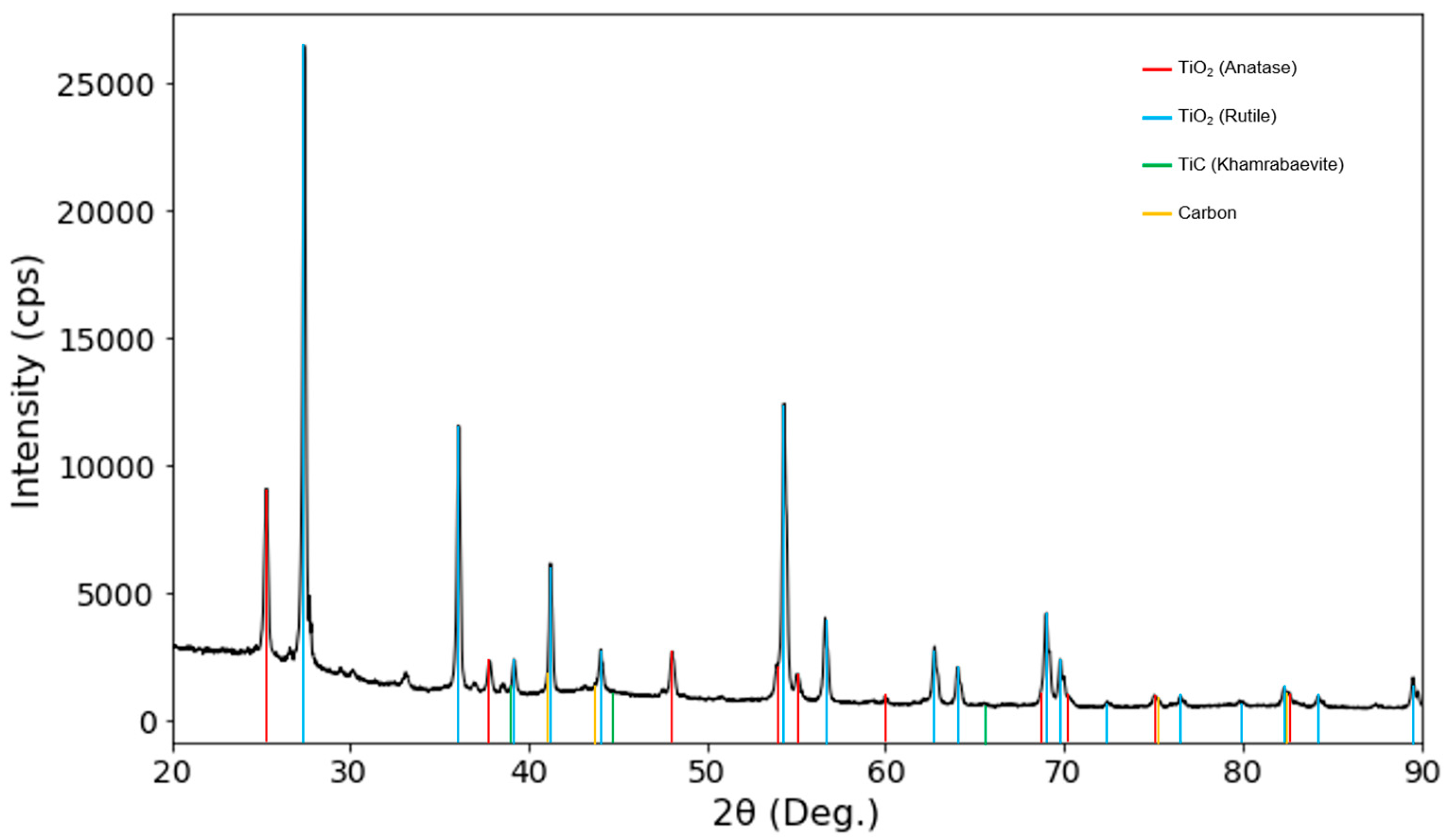
3.1. Structural Analysis

The images in Figure 3 below were obtained via SEM imaging of the coated substrate samples. The surface morphology of all three samples can be evaluated from these images. Different coating methods resulted in varying levels of agglomeration, cracking and surface roughness. It should be noted that in the 500 μm images (Figure 3A–C), the agglomerations of the coating can be seen reducing aperture size, with the pasted carbon sample having the highest level of agglomeration and the atomized coating sample having the lowest. These agglomerations have the possibility of restricting oil flow through the substrate, falsely attributing higher oleophobicity to the sample. However, even with the agglomeration of the TiO2 sample, the mixed coating demonstrated a higher contact angle and oil retention time.
Furthermore, thermal cracking of the filter coating is exhibited on all three samples. However, when analyzing the lower magnification SEM images, shown in Figure 3A–C, the atomized TiO2 sample display higher levels of thermal cracking across the entire sample. There are numerous methods to mitigate thermal cracking; the average linear coefficient of thermal expansion (CTE) for carbon steel has been cited to be 16.92 ppm/K [29], utilizing a coating with a similar CTE would reduce cracking and increase adherence to the substrate. In comparison, the pasted carbon and mixed-coating sample exhibited much lower levels of thermal cracking. This resulted in higher adhesion to the substrate at elevated temperatures and mitigated fatigue, accounting for the reusability of the mixed-coated substrate compared to the single-use TiO2 filter.

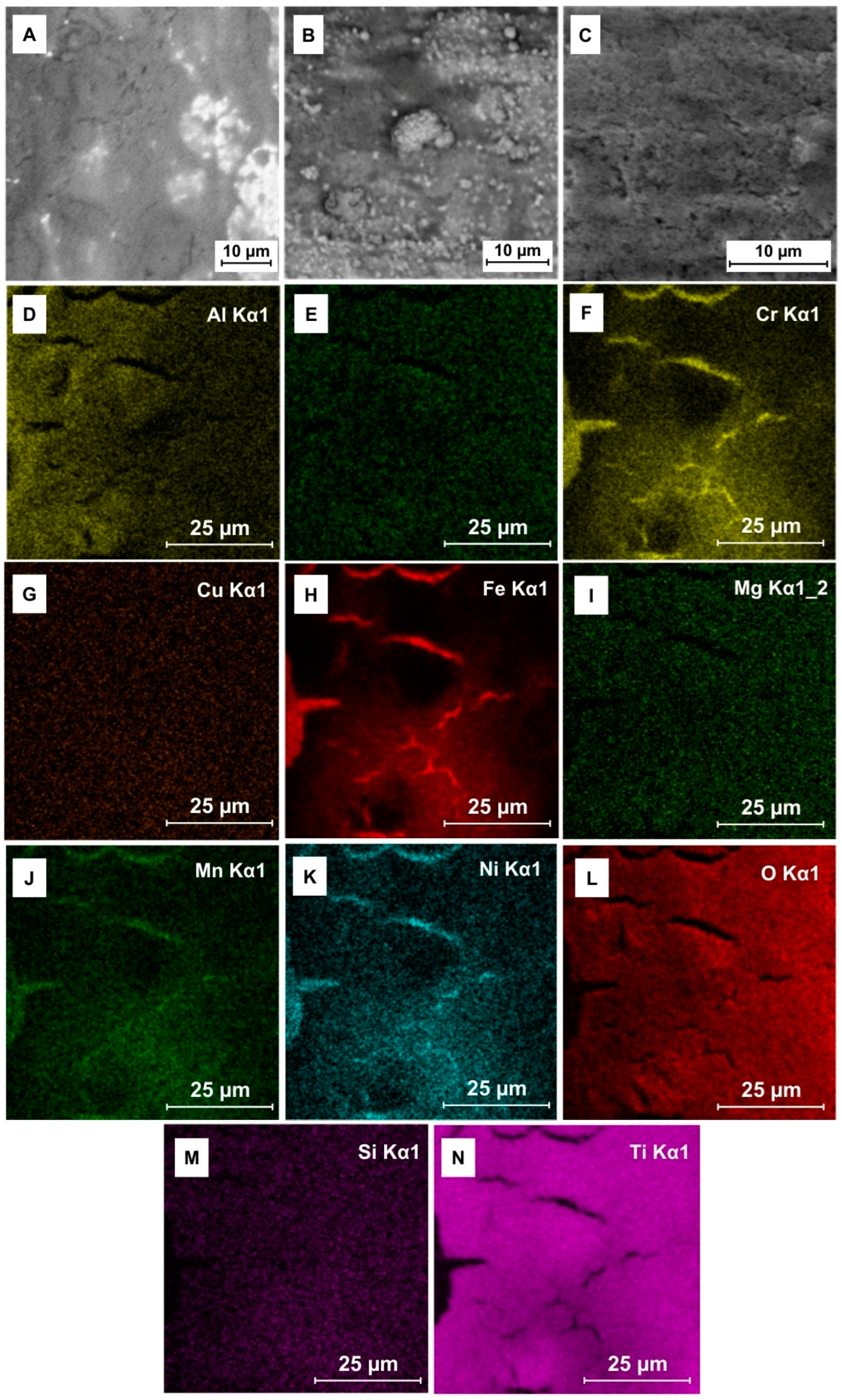
3.2. Elemental Analysis

Elemental analysis and structural characterization of the samples were conducted via XRD and EDS testing. An XRD was performed with a Rigaku Ultima III at the Irvine Materials Research Institute (IMRI). Figure 4 was obtained from the room temperature, non-heat-treated TiO2 powder utilized for the filter coating, the peak at the 2 θ value of 24.8° confirmed the anatase phase of TiO2 [43]. Anatase TiO2 has been cited as having higher photocatalytic activity than rutile TiO2 as a result of higher hydroxyl groups, surface area, and porosity [44,45], providing higher self-cleaning abilities practical for real-world applications.
Figure 5 was obtained from the atomized mixed-coating powder after sintering at 800 °C for 45 min. The graph depicts an increase in rutile-phase TiO2 and lower anatase phase fractions compared to the non-heat-treated TiO2. Rutile TiO2 is thermodynamically favored at higher temperatures [46,47]. Temperatures above 600 °C have been cited to frequent phase transitions from anatase into the rutile phase, with a lower capacity of 270 mA h g−1 [47,48,49,50]. It should be noted that temperature-driven phase transitions are dependent on the particle size and processing method, which could account for the wide range of temperatures from 400 to 1200 °C cited in the literature [50,51]. However, when considering temperature-dependent kinetics in air, bulk anatase phase was considered to irreversibly transition to rutile at approximately 600 °C [50,52,53]. Thus, the atomized samples were sintered at 450 °C to retain higher anatase phase fractions. There have been numerous articles discussing the use of additives to disrupt the transition from anatase to rutile. The use of acetic acid, benzoic acid, and aluminum and iron doping have all been shown to inhibit the transition from anatase to rutile [54,55,56] at higher temperatures. Investigating these inhibitory effects could be beneficial to retain higher anatase phase fractions while preserving the thermal driving force for Ti-C bonding.
Further XRD analysis depicts the formation of the TiC khamrabaevite. The bonding temperature of titanium to carbon has been cited to occur in the range of 400 °C–1050 °C, varying based on the structure of titanium, bonding process, and carbon concentration [49,57]. An article discussing carbon-doped titanium dioxide describes the mechanism of replacing a lattice oxygen with a carbon molecule in anatase TiO2. At 426.85 °C, Ti-O bonds are ruptured, and replaced by Ti-C bonds in the lattice [58].

3.3. Trace Element EDS

Elemental composition analysis of the coated filter was performed using energy dispersive-spectroscopy (EDS) with the Tescan Gaia 3 scanning electron microscope at the IMRI. EDS analysis provides critical insight into the elemental distribution across the filter coating, confirming the presence of key trace elements. The relative abundance of elements was visualized using EDS color maps, which illustrate spatial variations in elemental composition. To ensure statistical accuracy, point spectrum analysis was conducted at 10 randomized locations on the atomized mixed-coating sample shown in Figure 6C. The averaged spectrum data revealed that the coating primarily consisted of 40.72% by weight iron (Fe) related to the substrate material, 25.29% oxygen (O), 17.84% titanium (Ti), and 6.29% carbon (C). It should also be noted that the EDS analysis has the possibility of detecting contaminants in the sample. One example would be an elevated levels of oxygen that could be attributed to the surface oxide layer of stainless steels. These findings highlight the composition and potential interactions of the coating materials, which may influence the filter’s performance in oil separation applications.

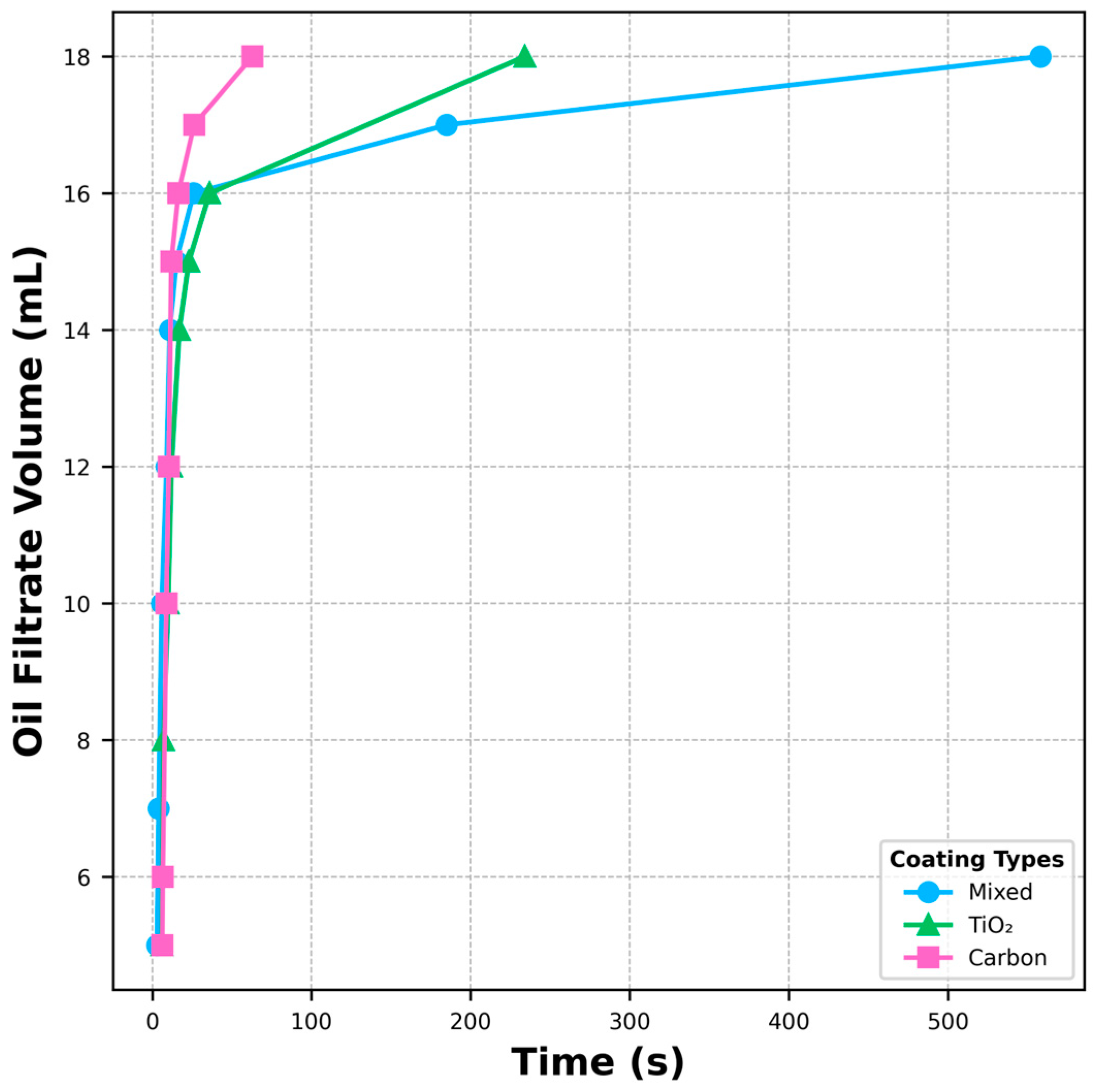
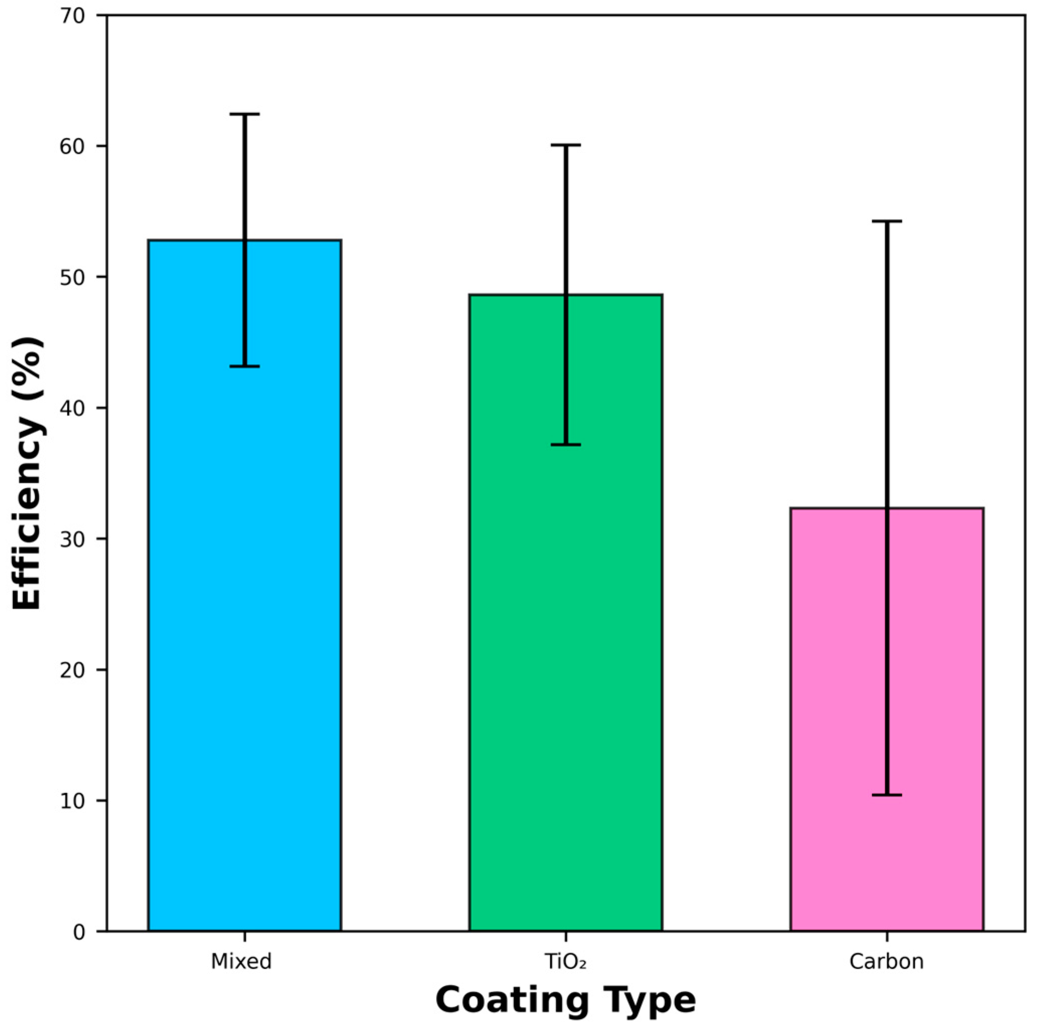
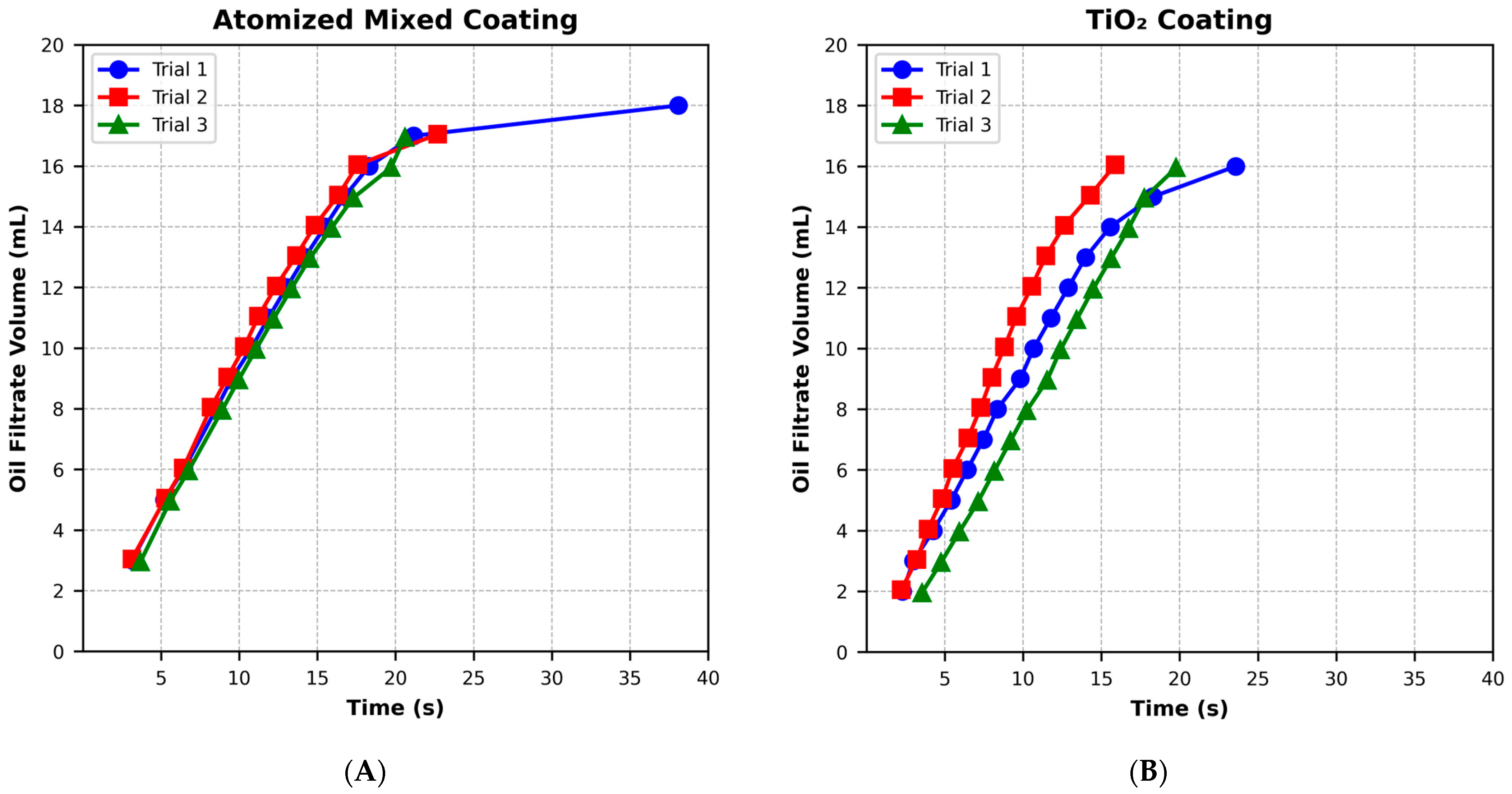
3.4. Oil Filtration and Oil–Water Separation Efficiency

Figure 7 presents the results of the oil filtration test conducted on various coating samples. A lower volume of oil filtrate indicates enhanced oleophobic properties and improved oil–water separation efficiency. While all three filters demonstrated filtration capability, the atomized mixed-coating filter exhibited superior performance compared to both carbon and TiO2-coated filters. This enhanced efficiency highlights the potential for improved reusability of the mixed-coating filter relative to previous iterations employing a TiO2 coating.
The oil retention efficiency of each filter was assessed by analyzing the ratio of retained oil to filtrate. The mixed-coating filter exhibited a greater capacity to retain oil over extended periods compared to the TiO2 and carbon-coated filters. This prolonged retention contributed to its higher overall filtration efficiency, as demonstrated in Figure 8.
Figure 9 demonstrates the reusability of the carbon-modified TiO2 composite coating and the traditional TiO2 coating. A comparison of these two coatings was conducted as both demonstrated high filtration capabilities compared to the carbon coating. The graph depicting the successive trials for the carbon-modified TiO2 composite (mixed) coating demonstrates little variation in the oil filtration as a function of time for each trial. Comparatively, the TiO2 coating exhibited a drop in its ability to retain surface oil after its first use in trial 1. These findings reinforce the higher performance of the carbon-modified coating for multiple uses compared to the TiO2 coating. The gravity filtration apparatus and video demonstrations of the oil/water separation performance of the coated filter are provided in the Supplementary Materials.

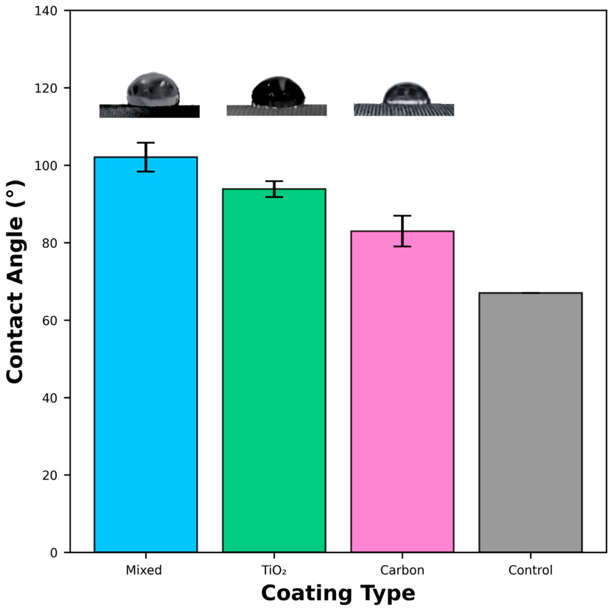
3.5. Wettability of Different Coating Methods

Figure 10 depicts the data analysis of the static contact angles measured for the composite, carbon, and TiO2 coatings, as well as a non-coated substrate used as a control. A contact angle measures the interaction between a droplet and a surface, quantifying surface tension using Young’s Equation [59]. Wettability refers to the capacity of a liquid to sustain contact with a surface, influenced by the liquid’s surface tension and the interaction at the liquid–surface interface [59]. A high contact angle indicates low wettability, which means a droplet will remain cohesive and not spread across the surface. A low contact angle indicates high wettability, which means a droplet will adhere and spread across the surface [60,61,62].
For a water droplet, a low contact angle indicates high wettability, typically allowing water and other polar liquids to pass through. All coated filters were tested with water to confirm that they retained hydrophilic properties of the control filter. Water droplets were absorbed into the filter too quickly to measure a contact angle, indicating very high hydrophilicity.
For an oil drop, a high contact angle signifies low wettability to nonpolar liquids, suggesting that oil would be retained on the coated filter. Studies support that a higher oil droplet contact angle indicates higher oleophobicity [61,62]. The control mesh has a contact angle of approximately 67°. Both the carbon and the control mesh have a contact angle value is less than 90°; thus, these filters harbor no oleophobic properties. Both the composite and TiO2 coatings exhibited higher contact angles than 90°, indicating their oleophobicity. A comparison between the composite and TiO2 filter contact angles demonstrate 9.57 percent increase in the composite filter over the TiO2-coated filter. Recent projects leveraging titanium dioxide for its oleophobic properties have been able to achieve contact angles ranging from approximately 90° to 100° for single-coated substrates [17,18]. The composite-coated filter, manufactured with a single-layered coating of TiO2, exhibited a contact angle of 103°. This indicates the enhanced oleophobic properties of the composite coating.

4. Conclusions

Traditional TiO2 coatings have been vastly utilized for their oleophobic properties. This study highlights the effect of modifying traditional TiO2 coatings with a carbon black nanopowder. The results demonstrated a higher contact angle for the carbon modified coating, as well as the SEM imaging confirming greater adherence to the substrate when compared to traditional TiO2 and carbon coatings. These findings can be leveraged to create processes that effectively separate polar and non-polar compounds. One such application is for the recovery of surface oil from ocean spills, mitigating their environmental impacts. Moving forward, further studies exploring the TiC khamrabaevite effect on substrate performance could be investigated by analyzing the thermal expansion of the compound and other intrinsic properties it may hold. Further studies should also investigate additives to inhibit temperature-driven phase transitions from anatase to rutile. In doing so, the substrate would be able to retain higher fractions of anatase–phase TiO2 which has been cited to increase photocatalytic activity. This would be beneficial for the decomposition of organic pollutants that the filter may come in contact with. Overall, this research advances our understanding of effective coatings for oil–water separations and lays the foundation for future work in this field. By building upon these findings, future studies can further refine methodologies, expand applications, and drive innovations that have the potential to diminish the impact of ocean oil spills.

Supplementary Materials

The following supporting information can be downloaded at: https://www.mdpi.com/article/10.3390/separations12040083/s1, Figure S1: Gravity filtration apparatus for video demonstration; Video S1: Advanced separation ability of composite-coated substrate; Video S2: Scooping simulation of oil spills.

Author Contributions

Conceptualization, M.L.; methodology, A.-H.B., K.L., E.D., P.C.-A., A.R., Z.S. and J.W.; formal analysis, A.-H.B., K.L., E.D., P.C.-A., A.R., Z.S. and J.W.; investigation, A.-H.B., K.L., E.D., P.C.-A., A.R., Z.S. and J.W.; data curation, A.-H.B., K.L., E.D., P.C.-A., A.R., Z.S. and J.W.; writing—original draft preparation, A.-H.B., K.L., E.D., P.C.-A., A.R., Z.S., J.W.; writing—review and editing, M.L.; visualization, A.-H.B.; supervision, M.L.; project administration, M.L.; funding acquisition, M.L. All authors have read and agreed to the published version of the manuscript.

Funding

This work is partially funded by the California State University Council on Ocean Affairs, Science & Technology (COAST-GDP-2023-004).

Data Availability Statement

Data are contained within the article.

Acknowledgments

The authors would like to acknowledge the Irvine Materials Research Institute (IMRI) for their assistance with SEM, XRD, and EDS analysis.

Conflicts of Interest

The funders had no role in the design of the study; in the collection, analyses, or interpretation of data; in the writing of the manuscript; or in the decision to publish the results.

Abbreviations

The following abbreviations are used in this manuscript:
CTECoefficient of thermal expansion
EDSEnergy-dispersive spectroscopy
IMRIIrvine Materials Research Institute
SEMScanning electron microscope
XRDX-ray diffraction

References

  1. Our World Data. Oil Spills. Available online: https://ourworldindata.org/oil-spills (accessed on 1 January 2025).
  2. Friedland, A.; Relyea, R. Environmental Science for the AP® Course, 4th ed.; W.H. Freeman & Company: New York, NY, USA, 2023; ISBN 978-1-319-46948-1. [Google Scholar]
  3. Asif, Z.; Chen, Z.; An, C.; Dong, J. Environmental Impacts and Challenges Associated with Oil Spills on Shorelines. J. Mar. Sci. Eng. 2022, 10, 762. [Google Scholar] [CrossRef]
  4. 2023 DARRP Highlights: Over $92 Million to Restore 7 Polluted Waterways and Communities; National Oceanic and Atmospheric Administration (NOAA), Damage Assessment, Remediation, and Restoration Program (DARRP): Baton Rouge, LA, USA, 2023.
  5. US Environmental Protection Agency. Deepwater Horizon—BP Gulf of Mexico Oil Spill. Available online: https://www.epa.gov/enforcement/deepwater-horizon-bp-gulf-mexico-oil-spill (accessed on 25 January 2025).
  6. Our World Data. Energy Mix. Available online: https://ourworldindata.org/energy-mix (accessed on 1 January 2025).
  7. Oliveira, L.M.T.M.; Saleem, J.; Bazargan, A.; Duarte, J.L.D.S.; McKay, G.; Meili, L. Sorption as a Rapidly Response for Oil Spill Accidents: A Material and Mechanistic Approach. J. Hazard. Mater. 2021, 407, 124842. [Google Scholar] [CrossRef] [PubMed]
  8. Egyetem, Ó. (Ed.) Proceedings of the International Conference “Global Environmental Changes and Environmental Health: Environmental and Economic Impact on Sustainable Development”, 7th ICEEE—2016, Budapest, Hungary, 17–19 November 2016; Óbuda University: Budapest, Hungary, 2017. ISBN 978-963-449-063-0.
  9. Wahi, R.; Chuah, L.A.; Choong, T.S.Y.; Ngaini, Z.; Nourouzi, M.M. Oil Removal from Aqueous State by Natural Fibrous Sorbent: An Overview. Sep. Purif. Technol. 2013, 113, 51–63. [Google Scholar] [CrossRef]
  10. Prince, R.C. Oil Spill Dispersants: Boon or Bane? Environ. Sci. Technol. 2015, 49, 6376–6384. [Google Scholar] [CrossRef]
  11. How Do Oil Spills out at Sea Typically Get Cleaned up?|Response.Restoration.Noaa.Gov. Available online: https://response.restoration.noaa.gov/about/media/how-do-oil-spills-out-sea-typically-get-cleaned.html (accessed on 16 March 2025).
  12. Ventikos, N. A High-Level Synthesis of Oil Spill Response Equipment and Countermeasures. J. Hazard. Mater. 2004, 107, 51–58. [Google Scholar] [CrossRef]
  13. Understanding Oil Spills And Oil Spill Response. Available online: https://www.epa.gov/sites/default/files/2018-01/documents/ospguide99.pdf (accessed on 16 March 2025).
  14. Fritt-Rasmussen, J.; Wegeberg, S.; Gustavson, K. Review on Burn Residues from In Situ Burning of Oil Spills in Relation to Arctic Waters. Water. Air. Soil Pollut. 2015, 226, 329. [Google Scholar] [CrossRef]
  15. Baniasadi, M.; Mousavi, S.M. A Comprehensive Review on the Bioremediation of Oil Spills. In Microbial Action on Hydrocarbons; Kumar, V., Kumar, M., Prasad, R., Eds.; Springer: Singapore, 2018; pp. 223–254. ISBN 978-981-13-1839-9. [Google Scholar]
  16. Nakajima, A.; Koizumi, S.; Watanabe, T.; Hashimoto, K. Photoinduced Amphiphilic Surface on Polycrystalline Anatase TiO2 Thin Films. Langmuir 2000, 16, 7048–7050. [Google Scholar] [CrossRef]
  17. Ross, H.; Nguyen, H.; Nguyen, B.; Foster, A.; Salud, J.; Patino, M.; Gan, Y.X.; Li, M. Filter Modified with Hydrophilic and Oleophobic Coating for Efficient and Affordable Oil/Water Separation. Separations 2022, 9, 269. [Google Scholar] [CrossRef]
  18. Sico, J.; Tang, B.; Flores, D.; Mouawad, R.; Punsalan, R.; Gan, Y.X.; Li, M. Fabrication and Characterization of TiO2 Coatings on 304 Stainless-Steel Substrate for Efficient Oil/Water Separation. Coatings 2023, 13, 1920. [Google Scholar] [CrossRef]
  19. Yu, G.; Chen, Z.; Zhang, Z.; Zhang, P.; Jiang, Z. The Photocatalytic Activity and Stability of a Nanosized TiO2 Film Prepared by Carbon Black Modified Method. Catal. Today 2004, 90, 305–312. [Google Scholar] [CrossRef]
  20. Mao, C.-C.; Weng, H.-S. Promoting Effect of Adding Carbon Black to TiO2 for Aqueous Photocatalytic Degradation of Methyl Orange. Chem. Eng. J. 2009, 155, 744–749. [Google Scholar] [CrossRef]
  21. Li, L.; Zhu, W.; Zhang, P.; Chen, Z.; Han, W. Photocatalytic Oxidation and Ozonation of Catechol over Carbon-Black-Modified Nano-TiO2 Thin Films Supported on Al Sheet. Water Res. 2003, 37, 3646–3651. [Google Scholar] [CrossRef]
  22. Ma, J.; Tang, Y.; Lu, G.; Wang, Y.; Niu, W.; Fu, D.; Zhang, K.; Bahnemann, D.W.; Pan, J.H. Incorporating Mesoporous Anatase TiO2 Spheres to Conductive Carbon Black Filled PVDF Membrane for Self-Cleaning Photo(Electro)Catalytic Filtration. J. Phys. Chem. C 2023, 127, 7998–8005. [Google Scholar] [CrossRef]
  23. Tan, K.H.; Rahman, H.A.; Taib, H. Coating Layer and Influence of Transition Metal for Ferritic Stainless Steel Interconnector Solid Oxide Fuel Cell: A Review. Int. J. Hydrogen Energy 2019, 44, 30591–30605. [Google Scholar] [CrossRef]
  24. Mashreghi, A. Determining the Volume Thermal Expansion Coefficient of TiO2 Nanoparticle by Molecular Dynamics Simulation. Comput. Mater. Sci. 2012, 62, 60–64. [Google Scholar] [CrossRef]
  25. Fang, D.; Qie, J.; Deng, H. Study on Thermal Physical Properties of 304 Stainless Steel. In Proceedings of the 6th International Symposium on High-Temperature Metallurgical Processing, Orlando, FL, USA, March 15–19 2015; Jiang, T., Hwang, J.-Y., Alvear, F.G.R.F., Yücel, O., Mao, X., Sohn, H.Y., Ma, N., Mackey, P.J., Battle, T.P., Eds.; Springer International Publishing: Cham, Switzerland, 2015; pp. 99–104, ISBN 978-3-319-48603-1. [Google Scholar]
  26. Desai, P.D.; Ho, C.Y. Thermal Linear Expansion of Nine Selected AISI Stainless Steels; Thermophysical and Electronic Properties Information Analysis Center; CINDAS: Lafayette, IN, USA, 1978; p. 12. [Google Scholar]
  27. Qin, P.; Ma, H.; Cui, Y.; Liu, R.; Ju, P.; Wang, F.; Liu, L. The Corrosion Behavior of 316 Stainless Steel under the Cooperative Effect of Plastic Stress and UV Illumination in 3.5 Wt% NaCl Solution. Corros. Sci. 2023, 223, 111466. [Google Scholar] [CrossRef]
  28. Dhaiveegan, P.; Elangovan, N.; Nishimura, T.; Rajendran, N. Corrosion Behavior of 316L and 304 Stainless Steels Exposed to Industrial-Marine-Urban Environment: Field Study. RSC Adv. 2016, 6, 47314–47324. [Google Scholar] [CrossRef]
  29. Halmešová, K.; Trojanová, Z.; Koukolíková, M.; Brázda, M.; Džugan, J.; Huang, W. Effect of Laser Power on Thermal Properties of Multimaterial Structure Inconel 718 and Stainless Steel 316L Processed by Directed Energy Deposition. J. Alloys Compd. 2022, 927, 167082. [Google Scholar] [CrossRef]
  30. Yang, Y.; Liu, S.; Li, J.; Bian, X.; Guo, Z. Inhibitory Effect of Ni-P Coating on Thermal Expansion of Carbon Steel. Surf. Coat. Technol. 2017, 315, 484–489. [Google Scholar] [CrossRef]
  31. Anucha, C.B.; Altin, I.; Bacaksiz, E.; Stathopoulos, V.N. Titanium Dioxide (TiO2)-Based Photocatalyst Materials Activity Enhancement for Contaminants of Emerging Concern (CECs) Degradation: In the Light of Modification Strategies. Chem. Eng. J. Adv. 2022, 10, 100262. [Google Scholar] [CrossRef]
  32. Photocatalysis—An Overview|ScienceDirect Topics. Available online: https://www.sciencedirect.com/topics/earth-and-planetary-sciences/photocatalysis (accessed on 23 February 2025).
  33. Hsu, C.-Y.; Mahmoud, Z.H.; Abdullaev, S.; Ali, F.K.; Ali Naeem, Y.; Mzahim Mizher, R.; Morad Karim, M.; Abdulwahid, A.S.; Ahmadi, Z.; Habibzadeh, S.; et al. Nano Titanium Oxide (Nano-TiO2): A Review of Synthesis Methods, Properties, and Applications. Case Stud. Chem. Environ. Eng. 2024, 9, 100626. [Google Scholar] [CrossRef]
  34. Younis, A.B.; Haddad, Y.; Kosaristanova, L.; Smerkova, K. Titanium Dioxide Nanoparticles: Recent Progress in Antimicrobial Applications. WIREs Nanomed. Nanobiotechnol. 2023, 15, e1860. [Google Scholar] [CrossRef] [PubMed]
  35. Bodaghi, H.; Mostofi, Y.; Oromiehie, A.; Zamani, Z.; Ghanbarzadeh, B.; Costa, C.; Conte, A.; Del Nobile, M.A. Evaluation of the Photocatalytic Antimicrobial Effects of a TiO2 Nanocomposite Food Packaging Film by in vitro and in vivo Tests. LWT Food Sci. Technol. 2013, 50, 702–706. [Google Scholar] [CrossRef]
  36. Khodabakhshi, S.; Fulvio, P.F.; Andreoli, E. Carbon Black Reborn: Structure and Chemistry for Renewable Energy Harnessing. Carbon 2020, 162, 604–649. [Google Scholar] [CrossRef]
  37. Hsu, S.-W.; Yang, T.-S.; Chen, T.-K.; Wong, M.-S. Ion-Assisted Electron-Beam Evaporation of Carbon-Doped Titanium Oxide Films as Visible-Light Photocatalyst. Thin Solid Film. 2007, 515, 3521–3526. [Google Scholar] [CrossRef]
  38. Sadler, E.; Crick, C.R. Suction or Gravity-Fed Oil-Water Separation Using PDMS-Coated Glass Filters. Sustain. Mater. Technol. 2021, 29, e00321. [Google Scholar] [CrossRef]
  39. Kroeger, R.M.; DeKay, H.G. Measurement of Gravity Filtration. J. Am. Pharm. Assoc. 1951, 40, 213–215. [Google Scholar] [CrossRef]
  40. Madaeni, S.S.; Ghaemi, N. Characterization of Self-Cleaning RO Membranes Coated with TiO2 Particles under UV Irradiation. J. Membr. Sci. 2007, 303, 221–233. [Google Scholar] [CrossRef]
  41. Nishimoto, S.; Tomoishi, S.; Kameshima, Y.; Fujii, E.; Miyake, M. Self-Cleaning Efficiency of Titanium Dioxide Surface under Simultaneous UV Irradiation of Various Intensities and Water Flow. J. Ceram. Soc. Jpn. 2014, 122, 513–516. [Google Scholar] [CrossRef]
  42. Graziani, L.; Quagliarini, E.; Bondioli, F.; D’Orazio, M. Durability of Self-Cleaning TiO2 Coatings on Fired Clay Brick Façades: Effects of UV Exposure and Wet & Dry Cycles. Build. Environ. 2014, 71, 193–203. [Google Scholar] [CrossRef]
  43. Li, W.; Liang, R.; Hu, A.; Huang, Z.; Zhou, Y.N. Generation of Oxygen Vacancies in Visible Light Activated One-Dimensional Iodine TiO2 Photocatalysts. RSC Adv. 2014, 4, 36959–36966. [Google Scholar] [CrossRef]
  44. Tayade, R.J.; Surolia, P.K.; Kulkarni, R.G.; Jasra, R.V. Photocatalytic Degradation of Dyes and Organic Contaminants in Water Using Nanocrystalline Anatase and Rutile TiO2. Sci. Technol. Adv. Mater. 2007, 8, 455–462. [Google Scholar] [CrossRef]
  45. Naniwa, S.; Kato, K.; Yamakata, A.; Yamamoto, A.; Yoshida, H. A Quantitative Study on the Relationship of Specific Surface Area and Carrier Lifetime to Photocatalytic Activity of Anatase TiO2 Nanoparticles. ACS Catal. 2023, 13, 15212–15218. [Google Scholar] [CrossRef]
  46. Katal, R.; Masudy-Panah, S.; Tanhaei, M.; Farahani, M.H.D.A.; Jiangyong, H. A Review on the Synthesis of the Various Types of Anatase TiO2 Facets and Their Applications for Photocatalysis. Chem. Eng. J. 2020, 384, 123384. [Google Scholar] [CrossRef]
  47. Yao, S.; Ma, Y.; Xu, T.; Wang, Z.; Lv, P.; Zheng, J.; Ma, C.; Yu, K.; Wei, W.; Ostrikov, K. (Ken) Ti–C Bonds Reinforced TiO2@C Nanocomposite Na-Ion Battery Electrodes by Fluidized-Bed Plasma-Enhanced Chemical Vapor Deposition. Carbon 2021, 171, 524–531. [Google Scholar] [CrossRef]
  48. Su, D.; Dou, S.; Wang, G. Anatase TiO2: Better Anode Material Than Amorphous and Rutile Phases of TiO2 for Na-Ion Batteries. Chem. Mater. 2015, 27, 6022–6029. [Google Scholar] [CrossRef]
  49. Gorthy, R.; Wasa, A.; Land, J.G.; Yang, Z.; Heinemann, J.A.; Bishop, C.M.; Krumdieck, S.P. Effects of Post-Deposition Heat Treatment on Nanostructured TiO2-C Composite Structure and Antimicrobial Properties. Surf. Coat. Technol. 2021, 409, 126857. [Google Scholar] [CrossRef]
  50. Hanaor, D.A.H.; Sorrell, C.C. Review of the Anatase to Rutile Phase Transformation. J. Mater. Sci. 2011, 46, 855–874. [Google Scholar] [CrossRef]
  51. Dubey, R.S. Temperature-Dependent Phase Transformation of TiO2 Nanoparticles Synthesized by Sol-Gel Method. Mater. Lett. 2018, 215, 312–317. [Google Scholar] [CrossRef]
  52. Ghosh, T.B.; Dhabal, S.; Datta, A.K. On Crystallite Size Dependence of Phase Stability of Nanocrystalline TiO2. J. Appl. Phys. 2003, 94, 4577–4582. [Google Scholar] [CrossRef]
  53. Hirano, M.; Nakahara, C.; Ota, K.; Tanaike, O.; Inagaki, M. Photoactivity and Phase Stability of ZrO2-Doped Anatase-Type TiO2 Directly Formed as Nanometer-Sized Particles by Hydrolysis under Hydrothermal Conditions. J. Solid State Chem. 2003, 170, 39–47. [Google Scholar] [CrossRef]
  54. Rozman, N.; Sever Škapin, A.; Tobaldi, D.M.; Dražić, G.; Nadrah, P. Tailoring the Crystalline and Amorphous Phase Ratios of TiO2 through the Use of Organic Additives during Hydrothermal Synthesis. Ceram. Int. 2024, 50, 37033–37040. [Google Scholar] [CrossRef]
  55. Byrne, C.; Fagan, R.; Hinder, S.; McCormack, D.E.; Pillai, S.C. New Approach of Modifying the Anatase to Rutile Transition Temperature in TiO2 Photocatalysts. RSC Adv. 2016, 6, 95232–95238. [Google Scholar] [CrossRef]
  56. Vásquez, G.C.; Peche-Herrero, M.A.; Maestre, D.; Gianoncelli, A.; Ramírez-Castellanos, J.; Cremades, A.; González-Calbet, J.M.; Piqueras, J. Laser-Induced Anatase-to-Rutile Transition in TiO2 Nanoparticles: Promotion and Inhibition Effects by Fe and Al Doping and Achievement of Micropatterning. J. Phys. Chem. C 2015, 119, 11965–11974. [Google Scholar] [CrossRef]
  57. Yu, C.; Fu, L.; Xiao, H.; Lv, Q.; Gao, B. Effect of Carbon Content on the Microstructure and Bonding Properties of Hot-Rolling Pure Titanium Clad Carbon Steel Plates. Mater. Sci. Eng. A 2021, 820, 141572. [Google Scholar] [CrossRef]
  58. Di Valentin, C.; Pacchioni, G.; Selloni, A. Theory of Carbon Doping of Titanium Dioxide. Chem. Mater. 2005, 17, 6656–6665. [Google Scholar] [CrossRef]
  59. Moldoveanu, S.C.; David, V. Selection of the HPLC Method in Chemical Analysis; Elsevier: Chantilly, VA, USA, 2016; ISBN 978-0-12-803711-9. [Google Scholar]
  60. Ranowsky, A. Contact Angle and Surface Tension—A Fascinating Liaison. Available online: https://www.cscscientific.com/csc-scientific-blog/how-does-contact-angle-relate-to-surface-tension (accessed on 19 March 2025).
  61. Wang, Y.; Gong, X. Special Oleophobic and Hydrophilic Surfaces: Approaches, Mechanisms, and Applications. J. Mater. Chem. A 2017, 5, 3759–3773. [Google Scholar] [CrossRef]
  62. Wan Ikhsan, S.N.; Yusof, N.; Aziz, F.; Ismail, A.F.; Jaafar, J.; Wan Salleh, W.N.; Misdan, N. Superwetting Materials for Hydrophilic-Oleophobic Membrane in Oily Wastewater Treatment. J. Environ. Manag. 2021, 290, 112565. [Google Scholar] [CrossRef]
Figure 1. Stainless steel samples on mesh size 80 with (A) atomized TiO2 coating; (B) pasted TiO2 coating; and (C) atomized mixed coating.
Separations 12 00083 g001
Figure 2. Image J contact angle analysis of oil droplet on (A) the TiO2–carbon composite-coated layer using (B) the DropSnake method in drop Shape analysis plugin, (C) and the Low Bond Axisymmetric Drop Shape Analysis (LB-ADSA) method in the Drop Snake Analysis plugin.
Separations 12 00083 g002
Figure 3. Backscattered surface electron image of the (A) atomized TiO2 sample at 213× magnification, (B) atomized TiO2 sample at 997× magnification, (C) pasted carbon sample at 202× magnification, (D) pasted carbon sample at 1070× magnification, (E) atomized mixed coating sample at 206× magnification, and (F) atomized mixed coating sample at 1030× magnification.
Separations 12 00083 g003
Figure 4. X-ray diffractogram of non-heat-treated TiO2 nano powder with phase references.
Separations 12 00083 g004
Figure 5. X-ray diffractogram of 800 °C heat-treated mixed coating powder with phase references.
Separations 12 00083 g005
Figure 6. (A) Backscattered EDS mapping of atomized TiO2 sample; (B) backscattered EDS mapping of pasted carbon sample; (C) backscattered EDS mapping of atomized mixed coating sample; (DN) EDS mapping of specified elements.
Separations 12 00083 g006
Figure 7. Volume of oil filtrate as a function of time.
Separations 12 00083 g007
Figure 8. Filter oil retention efficiency.
Separations 12 00083 g008
Figure 9. Reusability testing of (A) atomized mixed and (B) TiO2 coatings.
Separations 12 00083 g009
Figure 10. Contact angles for differing coating methods.
Separations 12 00083 g010
Disclaimer/Publisher’s Note: The statements, opinions and data contained in all publications are solely those of the individual author(s) and contributor(s) and not of MDPI and/or the editor(s). MDPI and/or the editor(s) disclaim responsibility for any injury to people or property resulting from any ideas, methods, instructions or products referred to in the content.

