Article

Effect of Positively Charged Lipids (DOTAP) on the Insertion of Carbon Nanotubes into Liposomes and the Separation Performance of Thin-Film Nanocomposite Membranes

1
School of Municipal and Environmental Engineering, Shandong Jianzhu University, Jinan 250101, China
2
Shandong Shuifa Environmental Technology Co., Ltd., Jining 272000, China
3
State Key Laboratory of Biobased Material and Green Papermaking, Qilu University of Technology (Shandong Academy of Sciences), Jinan 250353, China
*
Authors to whom correspondence should be addressed.
Separations 2024, 11(3), 75; https://doi.org/10.3390/separations11030075
Submission received: 31 January 2024 / Revised: 14 February 2024 / Accepted: 21 February 2024 / Published: 28 February 2024
(This article belongs to the Special Issue Preparation of Membranes and Their Application in Separation)

Abstract

:
A liposome vesicle is an ideal carrier for carbon nanotubes (CNTs) serving as the water channel that allows for the fast transport of water molecules, thus enhancing membrane permeability. However, a low quantity of CNTs inserted into the liposome vesicle is an important factor that limits the further improvement of the membrane flux. In the present study, a positively charged lipid, (2,3-dioleoyloxy-propyl)-trimethylammonium-chloride (DOTAP), was introduced to 1,2-dioleoyl-sn-glycero-3-phosphoethanolamineon (DOPE) liposome vesicles to tailor the vesicle charge so as to evaluate the effect of positively charged DOTAP on the insertion of CNTs into liposomes and the separation performance of thin-film nanocomposite (TFN) membranes. The results show that the addition of DOTAP increased the quantity of CNTs inserted into the liposome vesicles, as the shrinkage rate (k) and permeability (Pf) of the liposome vesicles presented an obvious increase with the increased content of DOTAP in the liposome vesicles. Moreover, it contributed to a 252.3% higher water flux for TFN membranes containing DOPE/DOTAP2:1-CNT liposomes (the mass ratio between DOPE and DOTAP was 2:1) than thin-film composite (TFC) membranes. More importantly, it presented a 106.7% higher water flux for TFN membranes containing DOPE/DOTAP4:1-CNT liposomes (the mass ratio between DOPE and DOTAP was 4:1), which originated from the greater number of water channels that the CNTs provided in the liposome vesicles. Overall, positively charged DOTAP effectively tailored the vesicle charge, which provided a better carrier for the insertion of a greater quantity of CNTs and contributed to the higher permeability of the TFN membranes.

1. Introduction

With the continuous increase in the world’s population and the serious issue of water pollution, the shortage of fresh water is gradually becoming an important problem that needs to be addressed urgently [1]. Recently, reverse osmosis (RO) technology has become one of the main methods used to solve the fresh water crisis because of its great separation efficiency and low energy consumption, and it has shown great application value in the fields of seawater desalination, brackish water desalination and wastewater reuse [2]. As the core of RO technology, the properties of RO membranes directly affect the separation efficiency and the quality of water production, and the development of high-performance RO membranes has been the research hotspot in the membrane field in China and abroad. Polyamide thin-film composite (PA-TFC) membranes prepared using the interfacial polymerization method now occupy the dominant position in the RO membrane market [3,4]. However, due to the mutual restriction “trade-off” effect (the balance between water flux and salt rejection), TFC membranes always show low permeability but a high rejection of salt ions [5].
In 2007, Hoek et al. first proposed the concept of a “thin-film nanocomposite membrane (TFN)”, which gradually developed into one of the most effective means to break through the “trade-off” effect [6]. On the one hand, the incorporation of nanomaterials into the polyamide layer (PA) can provide a low-resistance water channel that promotes the permeation of water molecules. On the other hand, nanomaterials can induce the improvement of surface physical and chemical properties. Among the various nanomaterials, carbon nanotubes (CNTs) are deemed the most valuable nanofillers in overcoming the inherent limitation of the “trade-off” effect due to their physical and chemical properties, especially their ultra-fast rate of water transportation through the inner wall [7,8]. Currently, physical blending is the most commonly used method for preparing CNT-based TFN RO membranes, in which CNTs are added in the aqueous phase or organic phase. Johnson et al. incorporated zwitterion-modified CNTs in the PA layer, and the membrane flux increased from 11 L/m2·h for TFC membranes to 48 L/m2·h for TFN membranes with unchanged salt rejection [9]. Moreover, Zhang et al. first grafted an OH group to the surface of CNTs and then added them in the aqueous phase to prepare a TFN membrane. As a result, the TFN membrane exhibited water flux two times higher than that of a TFC membrane [10]. To date, several research groups have proved that CNTs indeed play an important role in enhancing membrane permeability and antifouling capacity [11,12,13].
In 2023, our group first reported the effect of a CNT nanochannel on the permeability of TFN membranes, in which COOH-SWCNT was inserted into 1,2-dioleoyl-sn-glycerol-3-phosphocholine (DOPC) liposomes and then embedded in the PA layer. The resultant membranes showed a 71.4% enhancement in water flux compared to TFC membranes, but only 25.6% was induced by the CNT nanochannel [14]. The relatively lower contribution of the CNT nanochannel was mainly caused by the low content of the inserted CNTs. Therefore, increasing the content of CNTs inserted into liposomes is important to further enhance membrane flux. Inspired by aquaporin (AQP)-based biomimetic membranes, liposome charge is an important factor in influencing the quantity of water channels inserted into liposomes. For instance, by introducing positively charged (2,3-dioleoxy-propyl) trimethylammonium chloride (DOTAP) phospholipid molecules into neutral phospholipid molecules (DOPE), Wang et al. found that the phospholipid vesicles’ penetration rate increased from 1561.5 μm·s−1 to 2537.7 μm·s−1, which was due to the regulation of the electrical properties of the phospholipid vesicles, thereby improving the loading ratio of the water channels [15]. Whether positively charged DOTAP can promote the insertion of more CNTs into liposomes and further contribute to increasing the water flux of TFN membranes deserves further comprehensive study.
In the current study, four types of liposomes (DOPE/DOTAP4:1, DOPE/DOTAP2:1 DOPE/DOTAP4:1-CNT and DOPE/DOTAP2:1-CNT liposomes) were synthesized and then incorporated into the selective layer to fabricate TFN membranes. Both the liposomes and TFN membranes were characterized using several advanced techniques, including the stop-flow test, XPS and SEM, to determine the effect of positively charged DOTAP on the insertion of CNTs into liposomes and the micro-structure of the PA layer. Furthermore, the influence of positively charged DOTAP on separation and antifouling performance was also evaluated. Overall, the current work was undertaken in an attempt to increase the quantity of CNTs inserted into liposomes and contribute to a higher water flux of TFN membranes.

2. Experimental Section

2.1. Preparation of Liposomes and CNT Liposomes

Liposomes and CNT liposomes were synthesized through a combined rehydration and extrusion method according to a previous study [14]. Of note, prior to the fabrication of the CNT liposomes, the length of the CNTs needed to be shortened. The detailed procedure can be found in Texts S1 and S2. Finally, DOPE/DOTAP4:1, DOPE/DOTAP2:1 DOPE/DOTAP4:1-CNT and DOPE/DOTAP2:1-CNT liposomes were prepared at a final concentration of about 1.0 mg/mL.

2.2. Fabrication of TFC and TFN Membranes

TFC and TFN membranes were prepared through the traditional IP reaction. Briefly, the top surface of the ultrafiltration membrane was first contacted with an aqueous solution (containing 2 w/v% MPD and 0.1 w/v% SDS) for 2 min. After removing the aqueous solution, the top surface was contacted with the organic phase (containing 0.1 w/v% TMC/n-hexane) for another 1 min. Then, the resultant TFC membranes were heat-treated in an oven for 5 min at 80 °C to complete the IP reaction. For the TFN membranes, various types of liposomes under different loading concentrations (ranging from 0.1 mg/mL to 1.0 mg/mL) were mixed with the aqueous solution, followed by the same preparation procedure as the TFC membranes. To distinguish the different TFN membranes, the membrane containing DOPE/DOTAP4:1 was denoted as TFN4:1-x, the membrane containing DOPE/DOTAP2:1 was denoted as TFN2:1-x, the membrane containing DOPE/DOTAP4:1-CNT was denoted as TFN4:1-CNT-x, and the membrane containing DOPE/DOTAP2:1-CNT was denoted as TFN2:1-CNT-x, where x represents the mass concentration (mg/mL) of the liposomes or CNT liposomes.

2.3. Membrane Separation Performance

The water flux and salt rejection of all the membranes were determined using a cycle cross-flow filtration setup (FlowMen-0021-HP, Figure S1). The effective membrane area was 24 cm2, and 2000 ppm NaCl was used as the feed solution. The membrane was pre-compressed under 18 bar until stable permeance was achieved. Then, the operation pressure was adjusted to 16 bar to determine water flux (J, L/m2⋅h) and salt rejection (R, %), which were calculated using the following equations [14]:
J = Δ V S · Δ t
R = 1 C 2 C 1
where ΔV (L), S (m2), Δt (h), C2 (g/L) and C1 (g/L) represent the permeate volume, the effective membrane area, the operation time and the permeate and feed concentrations, respectively. The other characterization method can be found in Text S3.

2.4. Antifouling Performance

The fouling test contained two cycles, and each cycle consisted of a fouling–rinsing process. In the fouling process, 500 ppm HA and 2000 ppm NaCl were first used as the feed solution to conduct fouling filtration for 9 h. After the fouling process, the membrane underwent 2 h of rinsing with DI water under a high flow rate without pressure input. Finally, the cleaned membrane was retested to determine the recovered flux. The flux recovery rate (FRR, %) and all antifouling parameters were calculated using the following equations [14]:
FRR = J 1 J 0 100 %
R t = TMP μ J = R m + R r + R i r
R m = TMP μ J 0
R t = TMP μ J 2
R r = TMP μ J 2 TMP μ J 1
R i r = R t R m R r
where J0 (L/m2·h) is the initial flux, J1 (L/m2·h) is the permeate flux at the end of the fouling process, J2 (L/m2·h) is the recovered water flux after rinsing, Rt (m−1) is the total membrane fouling resistance, Rm (m−1) is the intrinsic membrane resistance, Rr (m−1) is the hydraulic reversible resistance, Rir (m−1) is the irreversible fouling resistance, TMP (Pa) is the trans-membrane pressure, and μ (Pa·s) is the dynamic viscosity of the feed water.

3. Results and Discussion

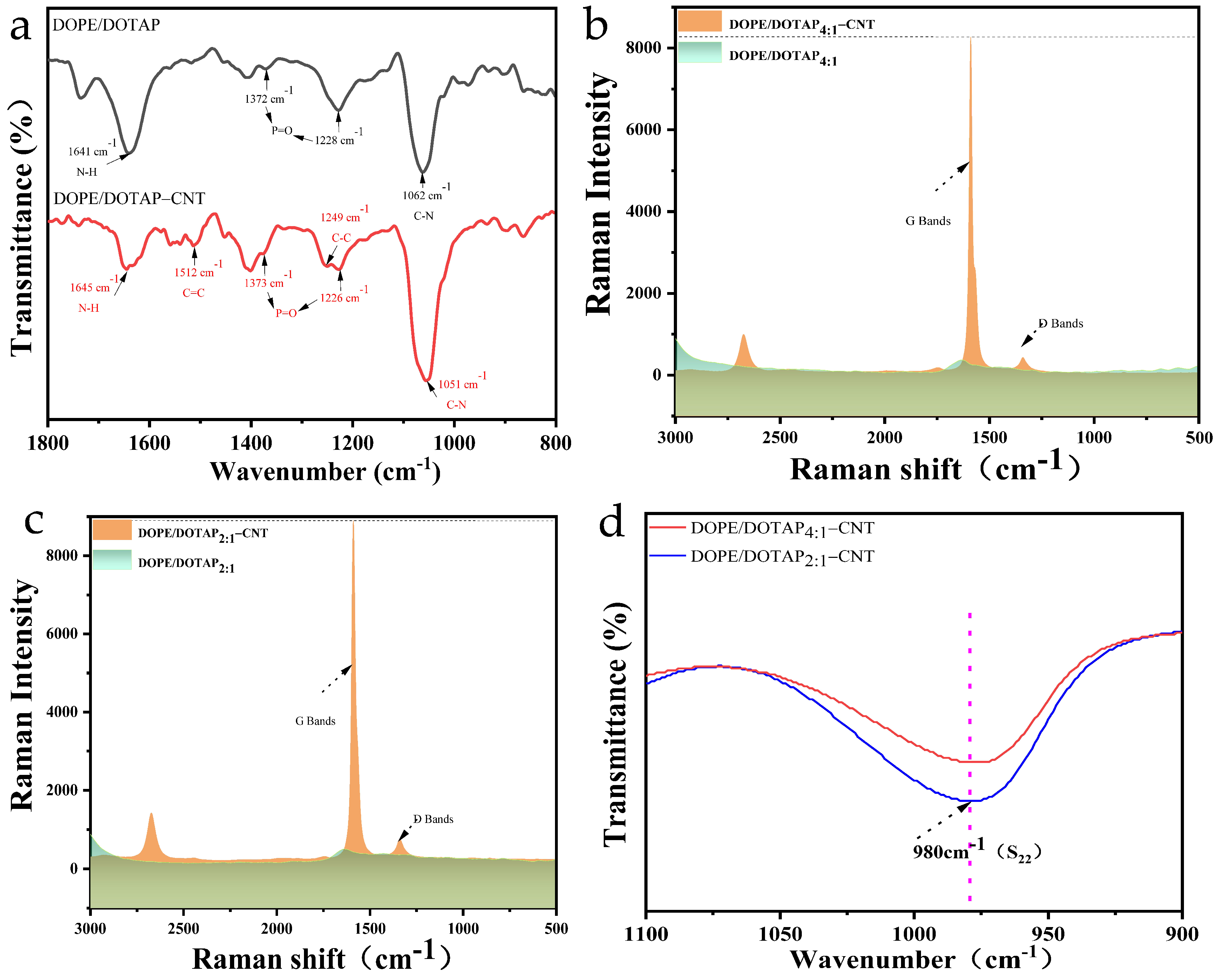
3.1. Characterization of Liposomes

The FTIR spectra of the different liposomes are shown in Figure 1a. Both the DOPE/DOTAP liposomes and the DOPE/DOTAP-CNT liposomes exhibited absorption peaks typical of lipids. In detail, the peak at 1062 cm−1 was assigned to the CN stretching of the primary amine. The peaks at 1228 cm−1 and 1372 cm−1 were assigned to the P=O stretching of phosphates provided by the DOPE lipid [16]. Additionally, the major peak at 1641 cm−1 originated from the NH bending and the abundance of DOTAP lipid in DOPE-DOTAP [17]. After the insertion of the CNTs, two new peaks appeared at 1512 cm−1 and 1249 cm−1, which were attributed to the C=C vibration in the backbone of the carbon nanotubes and the C–C vibration mode of the CNTs. It was noticed that the insertion of the CNTs induced the red/blue shift of the absorption peaks of the lipids, indicating complex interactions between the lipids and CNTs [18,19]. The Raman spectra of the DOPE/DOTAP liposomes and DOPE/DOTAP-CNT liposomes are displayed in Figure 1b,c. The characteristic signals of the G-band and D-band of the CNTs were observed clearly at 1590 cm−1 and 1340 cm−1, and the signal intensities of the G-band and D-band of the DOPE/DOTAP2:1-CNT liposomes were higher than those of the G-band and D-band of the DOPE/DOTAP4:1-CNT liposomes, which suggests that more CNTs were combined with the DOPE/DOTAP2:1 liposomes [20]. Additionally, the near-infrared (NIR) absorbance (Figure 1d) in the 980 nm region corresponding to the S22 transitions in the CNTs further demonstrated that positively charged lipids (DOTAP) increased the quantity of CNTs inserted into the liposomes, as DOPE/DOTAP2:1-CNT exhibited a higher signal intensity [21,22].
Table 1 summarizes the physical properties of the four different liposomes. For the DOPE/DOTAP4:1 liposome, the average size was 73.66 nm, with a low PDI value of about 0.124, and the morphology characterized using TEM can be observed in Figure S2. Additionally, it showed a slight positive charge of about 10.60 mV due to the incorporation of positively charged DOTAP [15]. When increasing the mass ratio of DOPE/DOTAP to 2:1 (DOPE/DOTAP2:1), the average size showed only a 3.52 nm increase, with tiny changes in the PDI value, which suggests that the greater quantity of DOTAP induced looser liposome vesicles. Additionally, the zeta potential notably increased to 25.03 mV, which was believed to be beneficial for the insertion of more CNTs into the liposomes due to the stronger electrostatic interaction [23]. Compared to the pure DOPE/DOTAP liposomes, the insertion of CNTs induced an increase in the average size of the DOPE/DOTAP-CNT liposomes (93.16 nm for DOPE/DOTAP4:1-CNT and 100.70 nm for DOPE/DOTAP2:1-CNT). Meanwhile, the PDI value also showed an apparent increase to 0.237, suggesting that the DOPE/DOTAP-CNT liposomes were less uniform than the pure DOPE/DOTAP liposomes [14]. Of note, the DOPE/DOTAP2:1-CNT liposomes exhibited a greater decrease in the zeta potential (from 25.03 mV to −2.45 mV) than the DOPE/DOTAP4:1-CNT liposomes (from 10.60 mV to −7.13 mV) due to the more negatively charged CNTs inserted into the liposomes.
Furthermore, Table 1 also displays the shrinkage rate (k) and the water permeability (Pf) of the DOPE/DOTAP and DOPE/DOTAP-CNT liposomes, and the relevant figure is shown in Figure S3. As observed, the pure DOPE/DOTAP liposomes showed small k values (21.48 s−1 for the DOPE/DOTAP4:1 liposomes and 23.47 s−1 for the DOPE/DOTAP2:1 liposomes) and low water permeability (50.52 μm·s−1 for the DOPE/DOTAP4:1 liposomes and 57.84 μm·s−1 for the DOPE/DOTAP2:1 liposomes). However, interestingly, the pure liposomes were not thoroughly impermeable, and the addition of DOTAP induced a slight increase in the permeability of the liposomes [24]. On the contrary, the DOPE/DOTAP4:1-CNT liposomes presented a sharp increase with a higher k value (206.17 s−1) within a short period, accompanied by twelve-times-higher permeability (616.21 μm·s−1), which resulted from the fast transport of water molecules through the inner wall of the CNTs. More importantly, the higher content of DOTAP in the mixed liposomes contributed to a higher permeability (712.91 μm·s−1), as the higher content of CNTs in the liposomes induced by the greater amount of DOTAP provided a more low-resistance water channel for the water molecules to pass through.

3.2. Characterization of TFC and TFN Membranes

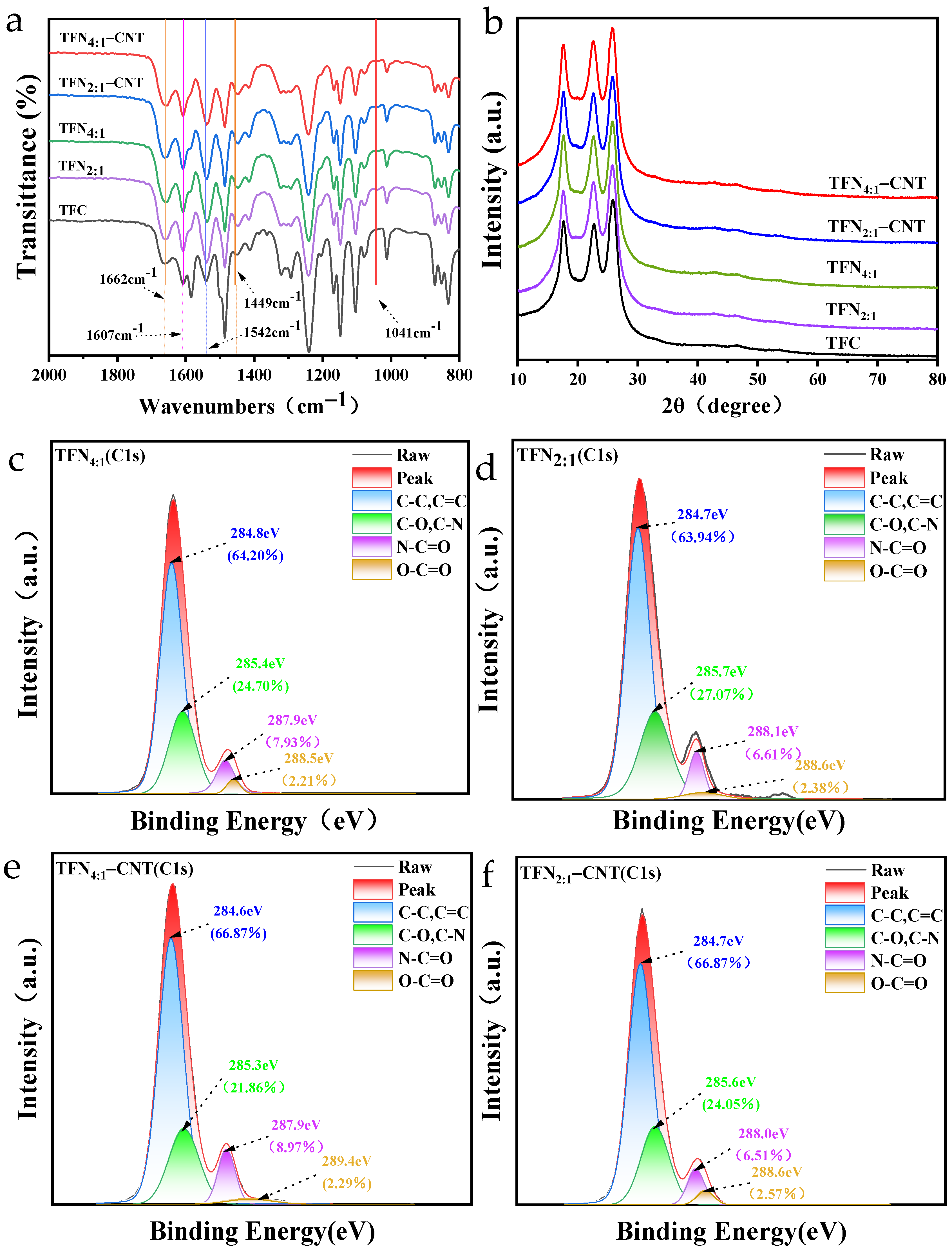
Surface Functional Groups of TFC and TFN Membranes

The FTIR spectra of the TFC and TFN membranes are displayed in Figure 2a. All the TFC and TFN membranes exhibited absorption peaks typical of polyamide membranes. In detail, the peaks at 1662 cm−1 and 1607 cm−1 originated from the C=O stretching vibrations (amide I), and the peak at 1542 cm−1 was assigned to the N–H and C–N stretching vibrations (amide II). In addition, the peak at 1449 cm−1 was caused by the C=O stretching and O–H bending of the carboxyl group, which was formed by the transformation of the residual acyl chloride group [25,26]. Compared with the TFC membranes, all the TFN membranes showed a new peak at 1041 cm−1, which was caused by the P–O–C group of phosphates provided by the DOPE lipid, proving the successful incorporation of the liposomes [27]. Figure 2b shows the XRD patterns of the TFC and TFN membranes. No obvious difference was found between the TFC and TFN membranes, as the liposomes did not possess a typical crystal structure, and the content of CNTs in the liposomes was tiny.
Figure 2c–f display the surface functional groups after fitting the C1s peak characterized by XPS. As shown, the C1s can be deconvoluted into C–C/C=C (284.6~284.8 eV), C–O/C–N (285.3~285.7 eV), N–C=O (287.9~288.1 eV) and O–C=O (288.5~289.4 eV), which are typical functional groups of the PA layer [28,29]. It should be emphasized that the content of surface COOH that transformed from the residual acyl chloride group was essential in influencing the membrane hydrophilicity and membrane permeability. As determined from the XPS results, compared with the TFN4:1 and TFN4:1-CNT membranes, the TFN2:1 and TFN2:1-CNT membranes presented a slightly higher content of COOH on the membrane surface, which was mostly caused by the greater amount of positively charged DOTAP that interfered with the IP process. Of note, the insertion of CNTs induced a further slight increase in the content of COOH on the membrane surface (2.38% for the TFN2:1 membrane to 2.57% for the TFN2:1-CNT membrane).
Table 2 summarizes the element content, RO/N and D of the four TFN membranes. Generally, the lower the D value, the looser structure of the PA layer formed, which may contribute to the enhancement of water permeation. As determined from Table 2, the cross-linking degree was negatively correlated with the content of COOH, and DOTAP played a significant role in decreasing the cross-linking degree. In detail, the cross-linking degree of the TFN4:1 and TFN4:1-CNT membranes was above 70%, which implies that a relatively dense PA layer formed on the membrane surface. Additionally, the influence of the CNTs on the cross-linking degree can be roughly ignored. When increasing the content of DOTAP in the liposomes to 2:1, it was found that the cross-linking degree of the TFN2:1 and TFN2:1-CNT membranes decreased from 70% to 50%, which demonstrates that the PA layers of TFN2:1 and TFN2:1-CNT were much looser than those of the TFN4:1 and TFN4:1-CNT membranes. It was speculated that DOTAP provided a more positive charge and allowed for the easier formation of a hydrogen bond between the liposomes and not only amine but also the benzene ring provided by MPD molecules; therefore, this limited the diffusion of MPD molecules into the reaction zone and, thus, the reaction with TMC, resulting in the formation of a relatively looser PA layer [30,31]. The structure and surface functional group changes in the PA layer were believed to be beneficial for water permeation.

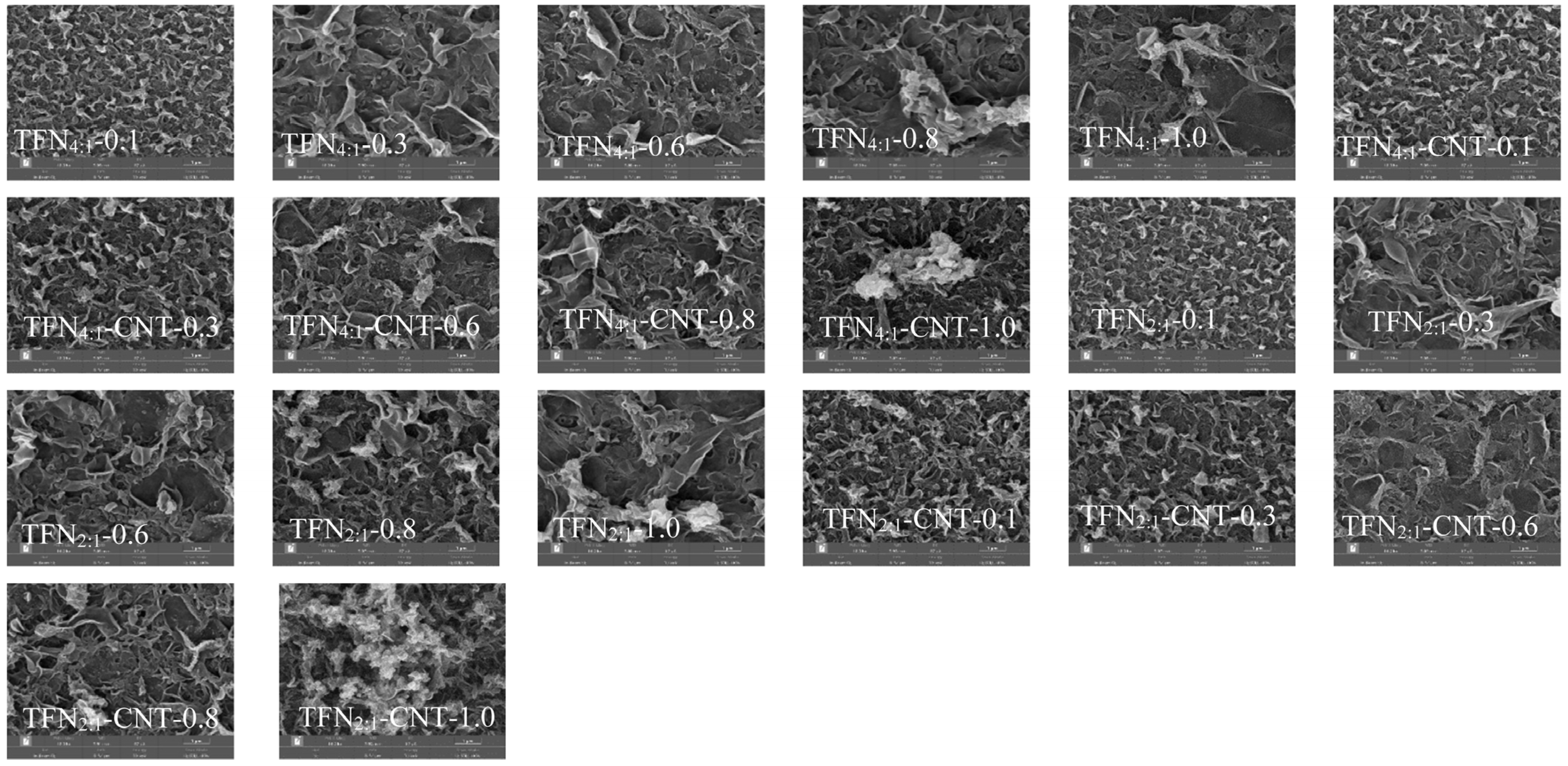
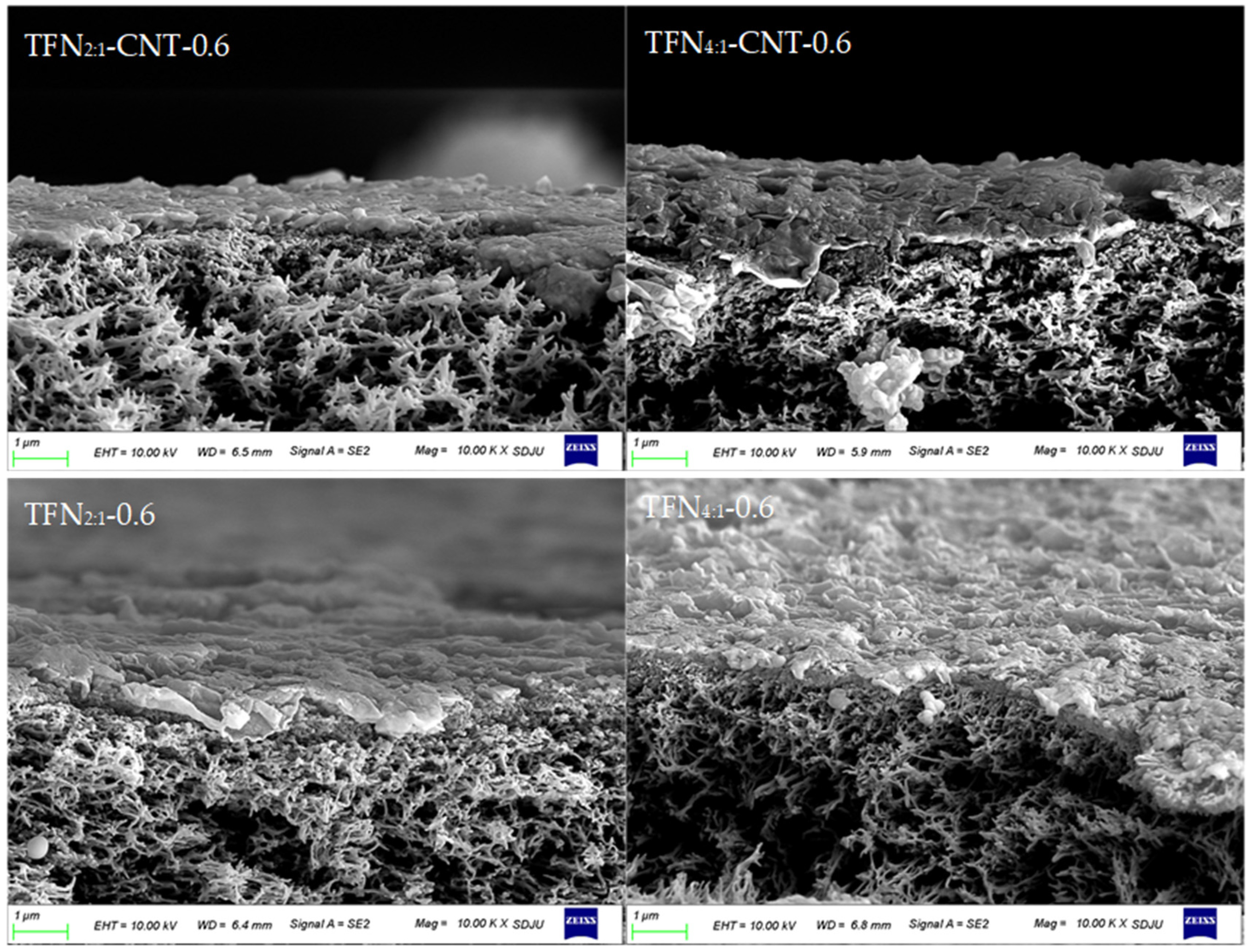
3.3. Surface Morphology and Roughness of TFC and TFN Membranes

Figure 3 and Figure S4 show the surface morphology of the TFN and TFC membranes. Rather than the traditional “ridge-and-valley” structure of the TFC membranes, the TFN membranes presented a “leaf-like” structure due to the incorporation of liposomes and CNT liposomes in the selective layer, and a higher loading concentration induced a larger “leaf-like” structure [14]. It has been reported that hydrophilic nanoparticles can enhance the miscibility of organic and aqueous phases, thus expanding the IP reaction zone and interfering with the chemical reaction between MPD and TMC [32]. It should be mentioned that, for the TFN2:1 and TFN2:1-CNT membranes, a slight difference from the TFN4:1 and TFN4:1-CNT membranes was observed. Specifically, under the same loading concentration of liposomes or CNT liposomes, the TFN2:1 and TFN2:1-CNT membranes seemed to present a larger “leaf-like” structure on the membrane surface. Additionally, a rougher surface of the TFN2:1-CNT membranes could be observed, as shown in the cross-section image in Figure 4. It was speculated that the initially formed PA layer limited the amine monomer from permeating into the reaction region and reacting with TMC molecules due to the lower diffusion of the amine monomer discussed above; therefore, a non-uniform and larger “leaf-like” structure developed on the membrane surface. Of note, the insertion of CNTs into the liposomes induced obvious aggregation under a higher loading concentration (1.0 mg/mL), and the TFN2:1-CNT membranes exhibited the most serious aggregation among the four different TFN membranes, which was likely caused by the nano-effect of the CNTs, as the TFN2:1-CNT membrane possessed a greater quantity of CNTs inserted into the liposomes. Table 3 summarizes the surface roughness of the TFC and TFN membranes under a 0.6 mg/mL loading concentration of liposomes and CNT liposomes, and the relevant AFM images are displayed in Figure S5. It can be clearly seen that all the TFN membranes exhibited a higher roughness than the TFC membranes, which resulted from the large “leaf-like” structure. Additionally, the TFN2:1-CNT-0.6 membranes exhibited the roughest surface, which is in accordance with the observation derived from the cross-section images. As discussed above, positively charged DOTAP resulted in a greater quantity of CNTs inserted into the liposomes and a higher surface roughness of the TFN membranes, which was no doubt beneficial for membrane permeability.

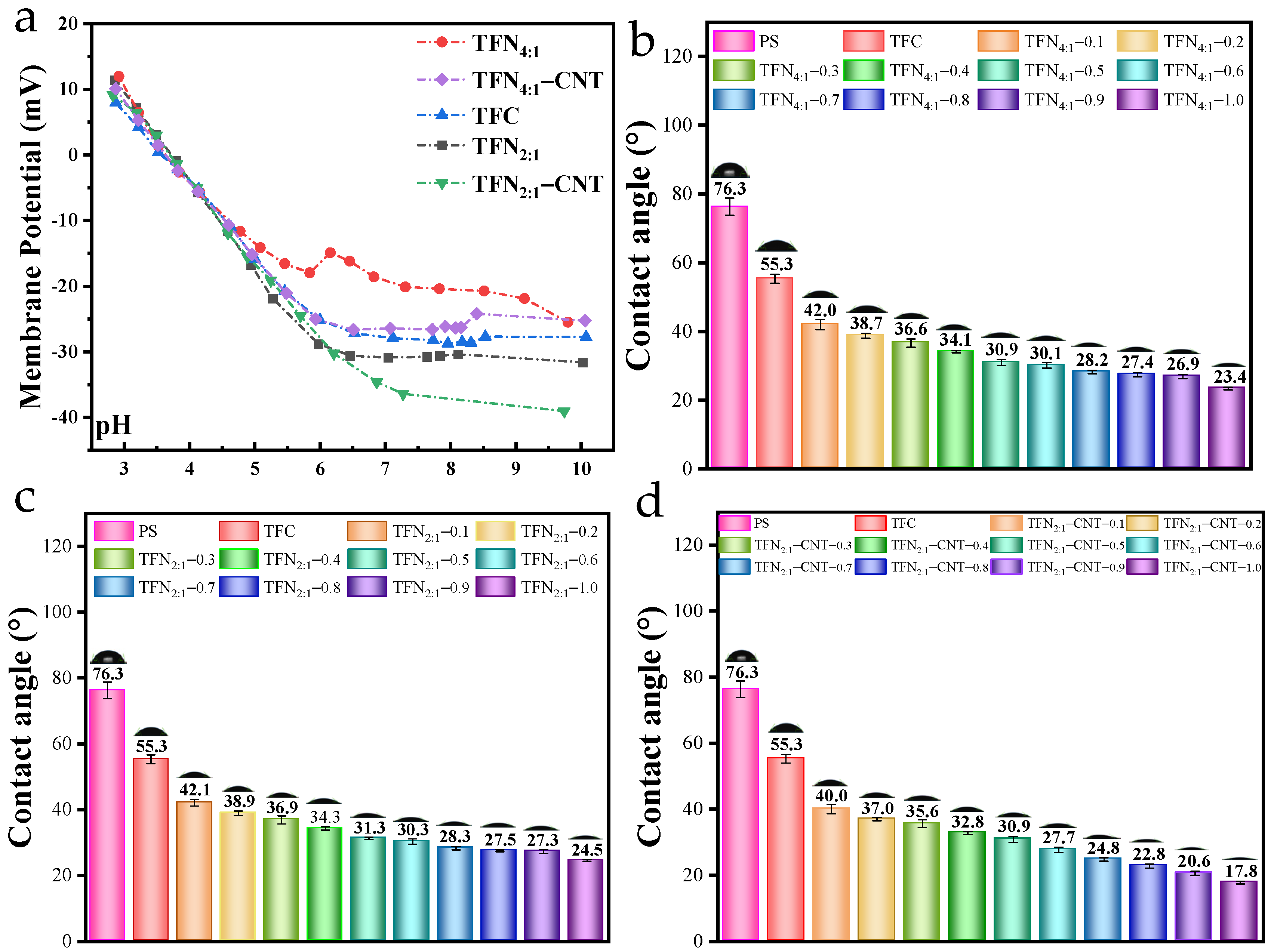
3.4. Membrane Potential and Surface Hydrophilicity of TFC and TFN Membranes

Figure 5a displays the membrane potential of the TFC and TFN membranes. Generally, the protonation of amine groups leads to a positive membrane charge at a low pH, while the deprotonation of carboxylic acid groups leads to a negative charge at a high pH [33]. As observed in Figure 5a, all the membranes showed a decreasing trend of the membrane potential from pH = 3 to pH = 10. The membrane potential of the four TFN membranes under a 0.6 mg/mL loading concentration followed the order of TFN2:1-CNT-0.6 < TFN2:1-0.6 < TFN4:1-CNT-0.6 < TFN4:1-0.6, which was mainly related to the surface COOH content, as determined using XPS. Figure 5b–d reflect the hydrophilicity of the TFN4:1 membrane, TFN2:1 membrane and TFN2:1-CNT membrane under different loading concentrations. For the PS membrane, the contact angle was 76.3°. After the formation of the PA layer on the membrane surface, the contact angle decreased from 76.3° to 55.3°, which originated from the changes in the surface functional groups and micro-structure [3,16]. The incorporation of liposomes or CNT liposomes induced a further decrease in the contact angle, and the more liposomes or CNT liposomes incorporated, the smaller the contact angle obtained, which suggests that surface hydrophilicity was further improved. For the TFN4:1 membrane and TFN2:1 membrane, little difference was found in the contact angle. However, the insertion of CNTs into the liposomes caused a relatively obvious decrease in the contact angle of the TFN2:1-CNT membranes compared to the TFN4:1 membrane and TFN2:1 membrane. For example, under a 0.6 mg/mL loading concentration, the contact angle of the TFN2:1-CNT membrane was 27.7°, while the contact angles of the TFN4:1 membrane and TFN2:1 membrane were 30.1° and 30.3°. Although the decrease was small, it would still contribute to the fast spreading of water molecules on the membrane surface [2,5]. Except for the changes in the surface functional groups and structure (such as the COOH content and surface roughness) of all the TFN membranes, the presence of CNTs in the TFN2:1-CNT-0.6 membranes also played a vital role in improving surface hydrophilicity, as it could provide extra hydrogen bonds between CNTs and water molecules and further accelerate the spreading of water molecules on the membrane surface [7,34].

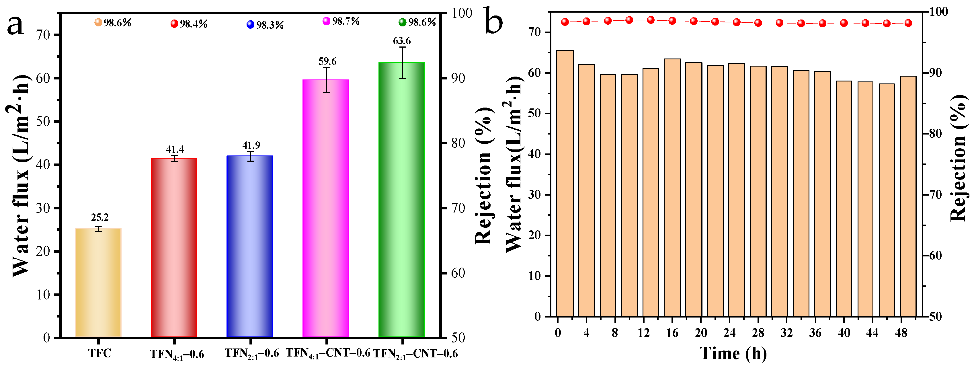
3.5. Separation Performance of TFC and TFN Membranes

Figure 6a shows the separation performance of the TFN membranes, and the change trend of the water flux and salt rejection of the TFN membranes under different loading concentrations can be observed in Figure S6. The TFC membrane exhibited a 25.2 L/m2·h water flux with 98.6% NaCl rejection, and the incorporation of liposomes and CNT liposomes caused a remarkable increase in water flux. More importantly, the salt rejection of the TFN membranes remained almost unchanged compared to that of the TFC membranes, which suggests that the liposomes or CNT liposomes did not destroy the integrity of the PA layer and introduced little defects in the selective layer [4,35]. For the TFN4:1 and TFN2:1 membranes, there was no obvious difference in water flux, but both of them exhibited a 1.67 times higher water flux than the TFC membranes. The enhancement of the membrane flux mainly accounted for the improved surface properties, such as hydrophilicity and surface roughness, which provided a better surface affinity for water molecules to adsorb and further penetrate across the membrane [36]. Moreover, as determined in the stop-flow test, the DOPE/DOTAP liposomes were not thoroughly impermeable to water molecules; therefore, they could also serve as low-resistance water channels and contribute to the increased water permeability. After the insertion of CNTs into the liposomes, a further increase in water flux was detected in the TFN-CNT membranes. The TFN4:1-CNT membranes showed a 36.7% increase in water flux compared to the TFN4:1 membranes and a 136.5% increase compared to the TFC membranes, which was caused by the fast transport of water molecules through the inner wall of the CNTs [37]. For the TFN2:1-CNT membranes, a higher water flux (63.6 L/m2·h) was obtained than for the TFN4:1-CNT membranes. As discussed above, the surface hydrophilicity and roughness of the TFN4:1-CNT and TFN2:1-CNT membranes showed nearly no difference, and the 1.1 times higher water flux observed for the TFN2:1-CNT membrane than for the TFN4:1-CNT membrane was mainly caused by the greater quantity of CNTs, which provided more water channels. The above observation further demonstrates that the positively charged DOTAP was of great significance in increasing the quantity of CNTs inserted into the liposomes and subsequently contributing to the better permeability of the TFN membranes. Table 4 compares the separation performances of the CNT-based RO membranes. It was found that DOPE/DOTAP2:1-CNT induced the highest enhancement in water flux with unchanged salt rejection compared to the other RO membranes.
Stability in the long-term RO test is essential for the practical application of TFN membranes. Figure 6b displays the change trend of the water flux and salt rejection of the TFN2:1-CNT-0.6 membranes during the 48 h RO test. It was satisfactory to find that the salt rejection for NaCl remained unchanged during the long-term RO test, which suggests that the TFN2:1-CNT-0.6 membrane possessed great stability, not only in terms of the stability of the PA layer, which could endure the high operation pressure, but also in terms of the stability of the CNT liposomes, which could exist stably in the PA layer. The water flux of the TFN membranes exhibited a slight fluctuation during the long-term RO test. During the first 9 h, the water flux presented an obvious decrease; this was mainly caused by the concentration polarization that occurred on the membrane surface, which weakened the effective transmembrane pressure [44]. Then, the water flux gradually increased and stayed relatively stable until the RO test was completed. The excellent stability of the current TFN membranes can be attributed to the great compatibility between the CNT liposomes and the PA layer. Additionally, the liposomes provided an extra active amine that could also react with the TMC molecules, thereby further enhancing its stability in the PA layer.

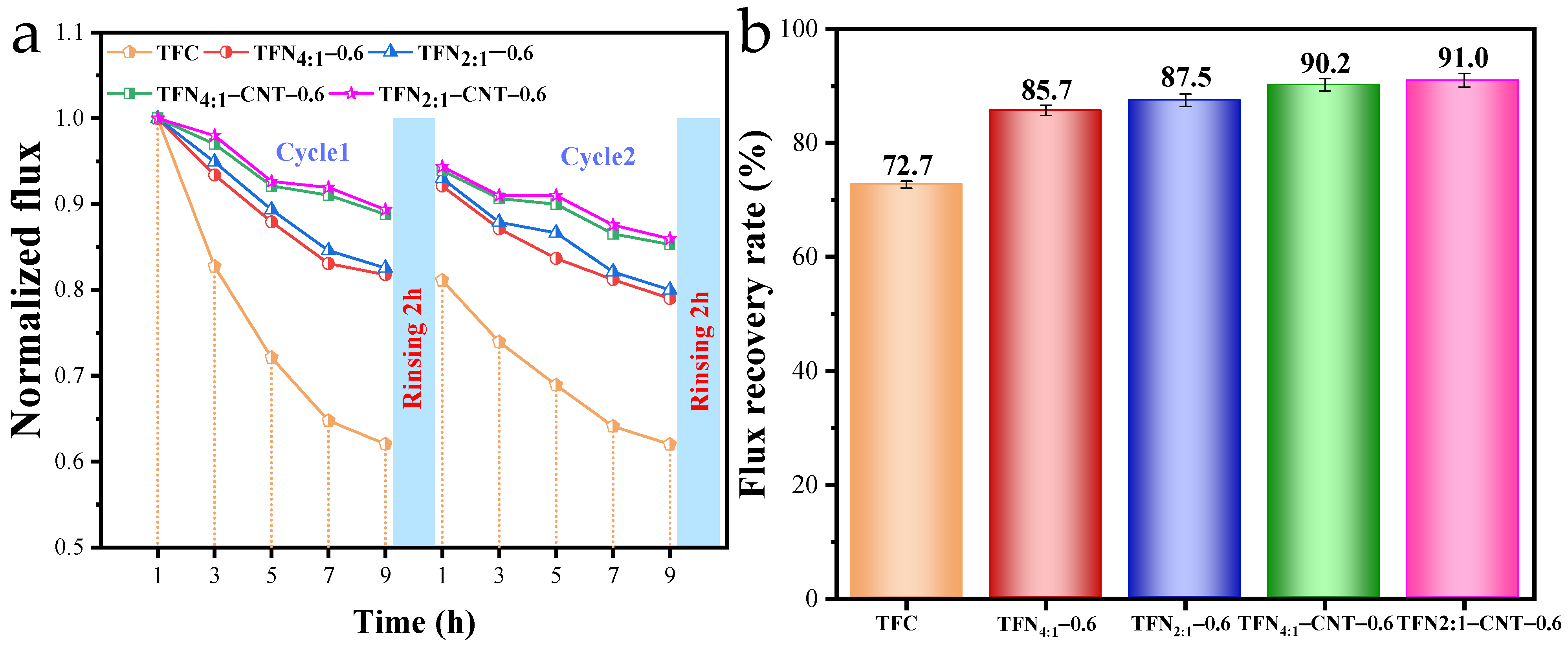
3.6. Antifouling Performance of TFC and TFN Membranes

Figure 7 shows the change trend of the water flux and flux recovery rate of the TFC and TFN membranes during the fouling test. As seen in Figure 7a, compared to the sharp decrease in the water flux of the TFC membranes, both the TFN and TFN-CNT membranes exhibited a relatively slower decreasing trend and a lower pollution level in cycle 1 and cycle 2, which was due to their improved surface properties. The final flux recovery rates (FRR) were 72.7%, 85.7%, 87.5%, 90.2% and 91.0% for the TFC and TFN membranes. Of note, the TFN2:1-CNT-0.6 membranes presented the best antifouling capacity; this was believed to be due to them having the best hydrophilicity and lowest surface negative charge, which reduced the absorption capacity of the organic foulant molecules and led to a boundary layer looser than that on the TFC membrane [45]. It should be noted that, although the TFN membranes presented satisfactory antifouling performance due to their improved surface properties, irreversible fouling still occurred on the membrane surface, as all the membranes showed a loss of initial permeate flux after washing compared to cycle 1. Table 5 summarizes the four antifouling parameters (Rt, Rm, Rr and Rir) of the TFC and TFN membranes. The TFC membranes suffered the most severe membrane fouling, with a total resistance of 3.52 × 10¹³ m−1. Irreversible fouling occupied the dominating position, with a resistance of about 9.60 × 10¹² m−1; this was mainly caused by the pore blocking and formation of a dense boundary layer, which was barely removed by the simple hydraulic backwash, thus inducing the severe flux decrease and low flux recovery rate [46]. On the contrary, the TFN2:1-CNT-0.6 membrane showed an obvious decrease in fouling resistance. More importantly, the irreversible fouling that occurred on the membrane surface gradually changed into reversible fouling. Specifically, the irreversible fouling resistance decreased from 9.60 × 10¹² m−1 to 1.07 × 10¹² m−1, and the reversible fouling resistance increased from 6.07 × 10¹² m−1 to 6.94 × 10¹² m−1. In other words, the foulants on the membrane were more easily flushed away through the physical cleaning method, which contributed to the highest FRR. The best antifouling capacity of the TFN2:1-CNT-0.6 membrane was attributed to its improved surface properties, such as surface hydrophilicity and surface charge. Additionally, a greater quantity of CNTs in the liposomes was also an important factor in enhancing the antifouling performance. The CNTs provided extra exclusion of HA molecules, and the inner wall was not easily blocked by HA; therefore, it could always supply the water channel after physical cleaning, and the more the better, which was beneficial for the recovery of the water flux.

4. Conclusions

In the present study, four types of liposomes (DOPE/DOTAP4:1, DOPE/DOTAP2:1 DOPE/DOTAP4:1-CNT and DOPE/DOTAP2:1-CNT liposomes) were synthesized and then incorporated into the selective layer to fabricate TFN membranes. The stop-flow results showed that a higher content of DOTAP in the liposome vesicles (DOPE/DOTAP2:1-CNT liposomes) induced a higher permeability than a lower content of DOTAP in the liposome vesicles (DOPE/DOTAP4:1-CNT liposomes), which resulted from the greater quantity of CNTs inserted into the liposome vesicles. The addition of DOPE/DOTAP2:1-CNT liposomes into the PA layer resulted in the lowest contact angle and surface charge and the highest surface roughness of the TFN membranes, which contributed to the best separation performance. This also resulted in a 152% flux enhancement compared with TFC membranes and a further 7% flux enhancement compared with TFN membranes containing DOPE/DOTAP4:1-CNT liposomes. Furthermore, the insertion of DOPE/DOTAP2:1-CNT liposomes into the PA layer led to a 91.0% flux recovery rate, with the highest reversible fouling resistance (6.94 × 10¹² m−1) and the lowest irreversible fouling resistance (1.07 × 10¹² m−1). In summary, the present work demonstrates that positively charged DOTAP possesses great potential in increasing the quantity of CNTs inserted into liposome vesicles, thus contributing to the better separation and antifouling performance of TFN membranes.

Supplementary Materials

The following supporting information can be downloaded at: https://www.mdpi.com/article/10.3390/separations11030075/s1, Supplementary material, including Text S1: Materials and chemicals; Text S2: Preparation of liposomes and CNT liposomes; Text S3: Characterization of liposomes and membranes; Figure S1: Experimental setup of RO; Figure S2: TEM images of DOPE/DOTAP4:1 (a), DOPE/DOTAP4:1-CNT (b), DOPE/DOTAP2:1 (c) and DOPE/DOTAP2:1-CNT (d) liposomes; Figure S3: Stop-flow light scattering curves (a) and osmotic water permeability (b) of liposomes; Figure S4: Surface morphology of TFC membranes; Figure S5: AFM images of TFC and TFN membranes; Figure S6: Water flux and salt rejection of four TFN membranes under different loading concentrations of liposomes.

Author Contributions

J.Z.: methodology, formal analysis, investigation, data curation, writing—original draft. J.S.: formal analysis, investigation, data curation; K.Z.: investigation, writing—review and editing. S.W.: formal analysis, investigation. W.D.: conceptualization, writing—review and editing, funding acquisition, supervision. Z.L.: software, formal analysis. All authors have read and agreed to the published version of the manuscript.

Funding

This research was supported by the Natural Science Foundation of Shandong Province (grant numbers: ZR2020QB066 and ZR2022QE190) and the China Postdoctoral Science Foundation (grant number: 2020M672122).

Data Availability Statement

Data will be made available upon request.

Conflicts of Interest

Author Wande Ding was employed by the company Shandong Shuifa Environmental Technology Co., Ltd. The remaining authors declare that the research was conducted in the absence of any commercial or financial relationships that could be construed as a potential conflict of interest.

References

  1. Thakur, A.K.; Sathyamurthy, R.; Velraj, R.; Saidur, R.; Lynch, I.; Venkatesh, R.; Kumar, P.G.; Kim, S.C.; Sillanpa, M. A novel solar absorber using activated carbon nanoparticles synthesized from bio-waste for the performance improvement of solar desalination unit. Desalination 2022, 527, 115564. [Google Scholar] [CrossRef]
  2. Li, R.H.; Li, Y.; Wu, H.; Yan, W.T.; Yu, C.Y.; Liu, L.F.; Gao, C.J. Structure regulation for synergistically improving the permeation properties of the reverse osmosis membrane based on an amphiphilic hyperbranched polymer. J. Membr. Sci. 2020, 608, 118143. [Google Scholar] [CrossRef]
  3. Zhang, Y.; Wan, Y.; Pan, G.Y.; Yan, H.; Yao, X.R.; Shi, H.W.; Tang, Y.J.; Wei, X.R.; Liu, Y.Q. Surface modification of polyamide reverse osmosis membrane with organic-inorganic hybrid material for antifouling. Appl. Surf. Sci. 2018, 433, 139–148. [Google Scholar] [CrossRef]
  4. Zhao, D.L.; Japip, S.; Zhang, Y.; Weber, M.; Maletzko, C.; Chung, T.-S. Emerging thin-film nanocomposite (TFN) membranes for reverse osmosis: A review. Water Res. 2020, 173, 115557. [Google Scholar] [CrossRef]
  5. Yu, C.J.; Cen, X.X.; Ao, D.; Qiao, Z.H.; Zhong, C.L. Preparation of thin-film composite membranes with ultrahigh MOFs loading through polymer-template MOFs induction secondary interfacial polymerization. Appl. Surf. Sci. 2023, 614, 156186. [Google Scholar] [CrossRef]
  6. Jeong, B.H.; Hoek, E.M.V.; Yan, Y.S.; Subramani, A.; Huang, X.F.; Hurwitz, G.; Ghosh, A.K.; Jawor, A. Interfacial polymerization of thin film nanocomposites: A new concept for reverse osmosis membranes. J. Membr. Sci. 2007, 294, 1–7. [Google Scholar] [CrossRef]
  7. Saleem, H.; Zaidi, S.J. Nanoparticles in reverse osmosis membranes for desalination: A state of the art review. Desalination 2020, 475, 114171. [Google Scholar] [CrossRef]
  8. Yang, D.C.; Castellano, R.J.; Silvy, R.P.; Lageshetty, S.K.; Praino, R.F.; Fornasiero, F.; Shan, J.W. Fast Water Transport through Subnanometer Diameter Vertically Aligned Carbon Nanotube Membranes. Nano Lett. 2023, 23, 4956–4964. [Google Scholar] [CrossRef] [PubMed]
  9. Chan, W.F.; Chen, H.Y.; Surapathi, A.; Taylor, M.G.; Shao, X.H.; Marand, E.; Johnson, J.K. Zwitterion Functionalized Carbon Nanotube/Polyamide Nanocomposite Membranes for Water Desalination. Acs Nano 2013, 7, 5308–5319. [Google Scholar] [CrossRef] [PubMed]
  10. Zheng, J.F.; Li, M.; Yu, K.; Hu, J.H.; Zhang, X.; Wang, L.J. Sulfonated multiwall carbon nanotubes assisted thin-film nanocomposite membrane with enhanced water flux and anti-fouling property. J. Membr. Sci. 2017, 524, 344–353. [Google Scholar] [CrossRef]
  11. Khalid, A.; Al-Juhani, A.A.; Al-Hamouz, O.C.; Laoui, T.; Khan, Z.; Atieh, M.A. Preparation and properties of nanocomposite polysulfone/multi-walled carbon nanotubes membranes for desalination. Desalination 2015, 367, 134–144. [Google Scholar] [CrossRef]
  12. Chan, W.F.; Marand, E.; Martin, S.M. Novel zwitterion functionalized carbon nanotube nanocomposite membranes for improved RO performance and surface anti-biofouling resistance. J. Membr. Sci. 2016, 509, 125–137. [Google Scholar] [CrossRef]
  13. Takeuchi, K.; Takizawa, Y.; Kitazawa, H.; Fujii, M.; Hosaka, K.; Ortiz-Medina, J.; Morelos-Gomez, A.; Cruz-Silva, R.; Fujishige, M.; Akuzawa, N.; et al. Salt rejection behavior of carbon nanotube-polyamide nanocomposite reverse osmosis membranes in several salt solutions. Desalination 2018, 443, 165–171. [Google Scholar] [CrossRef]
  14. Wang, Q.K.; Sun, J.Q.; Xue, W.J.; Zhao, G.L.; Ding, W.D.; Zhang, K.F.; Wang, S.; Li, Y.W. Effect of carbon nanotube nanochannel on the separation performance of thin-film nanocomposite (TFN) membranes. Desalination 2023, 546, 116216. [Google Scholar] [CrossRef]
  15. Wang, M.Q.; Wang, Z.N.; Wang, X.D.; Wang, S.Z.; Ding, W.D.; Gao, C.J. Layer-by-Layer Assembly of Aquaporin Z-Incorporated Biomimetic Membranes for Water Purification. Environ. Sci. Technol. 2015, 49, 3761–3768. [Google Scholar] [CrossRef] [PubMed]
  16. Divya, K.P.; Dharuman, V. Supported binary liposome vesicle-gold nanoparticle for enhanced label free DNA and protein sensing. Biosens. Bioelectron. 2017, 95, 168–173. [Google Scholar] [CrossRef] [PubMed]
  17. Vaidya, B.; Nayak, M.K.; Dash, D.; Agrawal, G.P.; Vyas, S.P. Development and characterization of site specific target sensitive liposomes for the delivery of thrombolytic agents. Int. J. Pharmaceut. 2011, 403, 254–261. [Google Scholar] [CrossRef]
  18. Martinez-Rubi, Y.; Gonzalez-Dominguez, J.M.; Ansón-Casaos, A.; Kingston, C.T.; Daroszewska, M.; Barnes, M.; Hubert, P.; Cattin, C.; Martinez, M.T.; Simard, B. Tailored SWCNT functionalization optimized for compatibility with epoxy matrices. Nanotechnology 2012, 23, 285701. [Google Scholar] [CrossRef] [PubMed]
  19. Tokgöz, S.R.; Kara, A.; Peksoz, A. Synthesis and characterization of poly(EGDMA--VPCA)/SWCNT composite films by surface polymerization method. Mat. Sci. Semicon. Proc. 2020, 116, 105144. [Google Scholar] [CrossRef]
  20. Song, X.J.; Wang, L.; Tang, C.Y.; Wang, Z.N.; Gao, C.J. Fabrication of carbon nanotubes incorporated double-skinned thin film nanocomposite membranes for enhanced separation performance and antifouling capability in forward osmosis process. Desalination 2015, 369, 1–9. [Google Scholar] [CrossRef]
  21. Tunuguntla, R.H.; Chen, X.; Belliveau, A.; Allen, F.I.; Noy, A. High-Yield Synthesis and Optical Properties of Carbon Nanotube Porins. J. Phys. Chem. C 2017, 121, 3117–3125. [Google Scholar] [CrossRef]
  22. Sanborn, J.R.; Chen, X.; Yao, Y.C.; Hammons, J.A.; Tunuguntla, R.H.; Zhang, Y.L.; Newcomb, C.C.; Soltis, J.A.; De Yoreo, J.J.; Van Buuren, A.; et al. Carbon Nanotube Porins in Amphiphilic Block Copolymers as Fully Synthetic Mimics of Biological Membranes. Adv. Mater. 2018, 30, 1803355. [Google Scholar] [CrossRef]
  23. Genova, J.; Chamati, H.; Petrov, M. Study of SOPC with embedded pristine and amide-functionalized single wall carbon nanotubes by DSC and FTIR spectroscopy. Colloid Surf. A 2020, 603, 125261. [Google Scholar] [CrossRef]
  24. Porter, C.J.; Werber, J.R.; Zhong, M.J.; Wilson, C.J.; Elimelech, M. Pathways and Challenges for Biomimetic Desalination Membranes with Sub-Nanometer Channels. Acs Nano 2020, 14, 10894–10916. [Google Scholar] [CrossRef] [PubMed]
  25. Yin, J.; Yang, Y.; Hu, Z.Q.; Deng, B.L. Attachment of silver nanoparticles (AgNPs) onto thin-film composite (TFC) membranes through covalent bonding to reduce membrane biofouling. J. Membr. Sci. 2013, 441, 73–82. [Google Scholar] [CrossRef]
  26. Fajardo-Diaz, J.L.; Takeuchi, K.; Morelos-Gomez, A.; Cruz-Silva, R.; Yamanaka, A.; Tejima, S.; Izu, K.; Saito, S.; Ito, I.; Maeda, J.; et al. Enhancing boron rejection in low-pressure reverse osmosis systems using a cellulose fiber-carbon nanotube nanocomposite polyamide membrane: A study on chemical structure and surface morphology. J. Membr. Sci. 2023, 679, 121691. [Google Scholar] [CrossRef]
  27. Ding, W.D.; Cai, J.; Yu, Z.Y.; Wang, Q.H.; Xu, Z.N.; Wang, Z.N.; Gao, C.J. Fabrication of an aquaporin-based forward osmosis membrane through covalent bonding of a lipid bilayer to a microporous support. J. Mater. Chem. A 2015, 3, 20118–20126. [Google Scholar] [CrossRef]
  28. Tayefeh, A.; Poursalehi, R.; Wiesner, M.; Mousavi, S.A. XPS study of size effects of Fe3O4 nanoparticles on crosslinking degree of magnetic TFN membrane. Polym. Test. 2019, 73, 232–241. [Google Scholar] [CrossRef]
  29. Shan, M.; Kang, H.; Xu, Z.; Li, N.; Jing, M.; Hu, Y.; Teng, K.; Qian, X.; Shi, J.; Liu, L. Decreased cross-linking in interfacial polymerization and heteromorphic support between nanoparticles: Towards high-water and low-solute flux of hybrid forward osmosis membrane. J. Colloid Interf. Sci. 2019, 548, 170–183. [Google Scholar] [CrossRef] [PubMed]
  30. Yang, Y.; Li, Y.; Goh, K.; Tan, C.H.; Wang, R. Liposomes-assisted fabrication of high performance thin film composite nanofiltration membrane. J. Membr. Sci. 2021, 620, 118833. [Google Scholar] [CrossRef]
  31. Liu, J.W. Interfacing Zwitterionic Liposomes with Inorganic Nanomaterials: Surface Forces, Membrane Integrity, and Applications. Langmuir 2016, 32, 4393–4404. [Google Scholar] [CrossRef]
  32. Baroña, G.N.B.; Lim, J.; Choi, M.; Jung, B. Interfacial polymerization of polyamide-aluminosilicate SWNT nanocomposite membranes for reverse osmosis. Desalination 2013, 325, 138–147. [Google Scholar] [CrossRef]
  33. Asempour, F.; Akbari, S.; Bai, D.; Emadzadeh, D.; Matsuura, T.; Kruczek, B. Improvement of stability and performance of functionalized halloysite nano tubes-based thin film nanocomposite membranes. J. Membr. Sci. 2018, 563, 470–480. [Google Scholar] [CrossRef]
  34. Goh, P.S.; Ismail, A.F. A review on inorganic membranes for desalination and wastewater treatment. Desalination 2018, 434, 60–80. [Google Scholar] [CrossRef]
  35. Li, K.; Lee, B.; Kim, Y. High performance reverse osmosis membrane with carbon nanotube support layer. J. Membr. Sci. 2019, 592, 117358. [Google Scholar] [CrossRef]
  36. Roy, K.; Mukherjee, A.; Maddela, N.R.; Chakraborty, S.; Shen, B.; Li, M.; Du, D.; Peng, Y.; Lu, F.; García Cruzatty, L.C. Outlook on the bottleneck of carbon nanotube in desalination and membrane-based water treatment—A review. J. Environ.Chem. Eng. 2020, 8, 103572. [Google Scholar] [CrossRef]
  37. Ali, S.; Rehman, S.A.U.; Luan, H.-Y.; Farid, M.U.; Huang, H. Challenges and opportunities in functional carbon nanotubes for membrane-based water treatment and desalination. Sci. Total Environ. 2019, 646, 1126–1139. [Google Scholar] [CrossRef]
  38. Zhang, L.; Shi, G.-Z.; Qiu, S.; Cheng, L.-H.; Chen, H.-L. Preparation of high-flux thin film nanocomposite reverse osmosis membranes by incorporating functionalized multi-walled carbon nanotubes. Desalin. Water Treat. 2011, 34, 19–24. [Google Scholar] [CrossRef]
  39. Zhao, H.; Qiu, S.; Wu, L.; Zhang, L.; Chen, H.; Gao, C. Improving the performance of polyamide reverse osmosis membrane by incorporation of modified multi-walled carbon nanotubes. J. Membr. Sci. 2014, 450, 249–256. [Google Scholar] [CrossRef]
  40. Wan Azelee, I.; Goh, P.S.; Lau, W.J.; Ismail, A.F. Facile acid treatment of multiwalled carbon nanotube-titania nanotube thin film nanocomposite membrane for reverse osmosis desalination. J. Clean. Prod. 2018, 181, 517–526. [Google Scholar] [CrossRef]
  41. Baek, Y.; Kim, H.J.; Kim, S.-H.; Lee, J.-C.; Yoon, J. Evaluation of carbon nanotube-polyamide thin-film nanocomposite reverse osmosis membrane: Surface properties, performance characteristics and fouling behavior. J. Ind. Eng. Chem. 2017, 56, 327–334. [Google Scholar] [CrossRef]
  42. Inukai, S.; Cruz-Silva, R.; Ortiz-Medina, J.; Morelos-Gomez, A.; Takeuchi, K.; Hayashi, T.; Tanioka, A.; Araki, T.; Tejima, S.; Noguchi, T.; et al. High-performance multi-functional reverse osmosis membranes obtained by carbon nanotube·polyamide nanocomposite. Sci. Rep. 2015, 5, 13562. [Google Scholar] [CrossRef] [PubMed]
  43. Farahbakhsh, J.; Delnavaz, M.; Vatanpour, V. Investigation of raw and oxidized multiwalled carbon nanotubes in fabrication of reverse osmosis polyamide membranes for improvement in desalination and antifouling properties. Desalination 2017, 410, 1–9. [Google Scholar] [CrossRef]
  44. Lee, K.P.; Arnot, T.C.; Mattia, D. A review of reverse osmosis membrane materials for desalination—Development to date and future potential. J. Membr. Sci. 2011, 370, 1–22. [Google Scholar] [CrossRef]
  45. Zhao, S.; Liao, Z.; Fane, A.; Li, J.; Tang, C.; Zheng, C.; Lin, J.; Kong, L. Engineering antifouling reverse osmosis membranes: A review. Desalination 2021, 499, 114857. [Google Scholar] [CrossRef]
  46. Zhang, T.; Li, Z.; Wang, W.; Wang, Y.; Gao, B.; Wang, Z. Enhanced antifouling and antimicrobial thin film nanocomposite membranes with incorporation of Palygorskite/titanium dioxide hybrid material. J. Colloid Interf. Sci. 2019, 537, 1–10. [Google Scholar] [CrossRef]
Figure 1. Physical and chemical properties of liposomes and CNT liposomes. (a) FTIR spectra, (b,c) Raman shift, (d) NTR-FTIR spectra of liposomes and CNT liposomes.
Separations 11 00075 g001
Figure 2. Surface functional groups of TFC and TFN membranes. (a) FTIR spectra of TFC and TFN membranes, (b) XPS spectra of TFC and TFN membranes, (cf) C 1s deconvoluted peaks in XPS spectra of TFN membranes.
Separations 11 00075 g002
Figure 3. Surface morphology of TFN membranes under different loading concentrations of liposomes (magnification, 15,000×).
Separations 11 00075 g003
Figure 4. Cross-section images of TFN membranes under 0.6 mg/mL loading concentration of liposomes and CNT liposomes.
Separations 11 00075 g004
Figure 5. Membrane potential (a) and surface hydrophilicity (bd) of TFC and TFN membranes.
Separations 11 00075 g005
Figure 6. Separation performance of TFC and TFN membranes (a) and stability of TFN2:1-CNT-0.6 membranes during 48 h RO test (b).
Separations 11 00075 g006
Figure 7. Decrease in water flux under antifouling test (a), FRR of TFC and TFN membranes (b).
Separations 11 00075 g007
Table 1. Physical properties of different liposomes.
Liposome TypeAverage Size (nm)PDIZeta Potential (mV)k (s−1)Pf (µm/s)
DOPE/DOTAP4:173.660.12410.6021.4850.52
DOPE/DOTAP4:1-CNT93.160.228−7.13206.17616.21
DOPE/DOTAP2:177.180.13125.0323.4757.84
DOPE/DOTAP2:1-CNT100.700.237−2.45221.73712.91
Table 2. Surface elemental composition of TFN membranes.
Membrane Surface Elemental Composition
C (%)N (%)O (%)P (%)RO/ND (%)
TFN4:176.3510.6312.590.431.1874.7
TFN4:1-CNT74.2211.7313.660.381.1677.2
TFN2:171.8411.8215.950.391.3555.4
TFN2:1-CNT74.8110.7416.30.151.3357.3
Table 3. Surface roughness of TFC and TFN membranes.
MembraneRoughness Parameters
Ra (nm)Rq (nm)Rmax (nm)
TFC87.4111812
TFN4:1-0.61431771129
TFN2:1-0.61451871307
TFN4:1-CNT-0.61511911457
TFN2:1-CNT-0.61582111724
Table 4. Comparison of the CNT-based RO performances between previous studies and present work.
CNT NanofillerWater Flux (L/m2·h)Salt RejectionReferences
CNT-COOH/PA26→71NaCl: 95%→82%[38]
CNT-Zwitterion/PA11→48NaCl: 97%→98%[9]
MWCNT-COOH/PA14→28NaCl: 95%→90%[39]
MWCNT/PA27→71NaCl: 97%→90%[12]
CNT-Zwitterionic/PA14→34NaCl: 98%→98%[40]
MWCNT-COOH/PA20→28NaCl: 97%→97%[41]
MWCNT-TNT/PA7→17NaCl: 98%→96%[42]
CNT/PA36→42NaCl: 99%→97%[43]
DOPE/DOTAP2:1-CNT 25.2→63.6NaCl: 98.6%→98.6%This work
Table 5. Antifouling parameters of TFC and TFN membranes.
MembraneRt (×1013 m−1)Rm (×1013 m−1)Rr (×1012 m−1)Rir (×1012 m−1)
TFC3.522.566.079.60
TFN4:1-0.61.461.251.242.09
TFN2:1-0.61.391.221.301.74
TFN4:1-CNT-0.61.121.016.461.10
TFN2:1-CNT-0.61.191.086.941.07
Disclaimer/Publisher’s Note: The statements, opinions and data contained in all publications are solely those of the individual author(s) and contributor(s) and not of MDPI and/or the editor(s). MDPI and/or the editor(s) disclaim responsibility for any injury to people or property resulting from any ideas, methods, instructions or products referred to in the content.

